EP0803938A1 - Connecteur à force d'insertion faible - Google Patents
Connecteur à force d'insertion faible Download PDFInfo
- Publication number
- EP0803938A1 EP0803938A1 EP97106923A EP97106923A EP0803938A1 EP 0803938 A1 EP0803938 A1 EP 0803938A1 EP 97106923 A EP97106923 A EP 97106923A EP 97106923 A EP97106923 A EP 97106923A EP 0803938 A1 EP0803938 A1 EP 0803938A1
- Authority
- EP
- European Patent Office
- Prior art keywords
- connector
- cam
- movable member
- fitting
- insertion force
- Prior art date
- Legal status (The legal status is an assumption and is not a legal conclusion. Google has not performed a legal analysis and makes no representation as to the accuracy of the status listed.)
- Withdrawn
Links
- 238000003780 insertion Methods 0.000 title claims abstract description 25
- 230000037431 insertion Effects 0.000 title claims abstract description 25
- 239000002184 metal Substances 0.000 description 2
- 230000005405 multipole Effects 0.000 description 2
- 230000000694 effects Effects 0.000 description 1
- 238000000034 method Methods 0.000 description 1
- 230000002093 peripheral effect Effects 0.000 description 1
Images





Classifications
-
- H—ELECTRICITY
- H01—ELECTRIC ELEMENTS
- H01R—ELECTRICALLY-CONDUCTIVE CONNECTIONS; STRUCTURAL ASSOCIATIONS OF A PLURALITY OF MUTUALLY-INSULATED ELECTRICAL CONNECTING ELEMENTS; COUPLING DEVICES; CURRENT COLLECTORS
- H01R13/00—Details of coupling devices of the kinds covered by groups H01R12/70 or H01R24/00 - H01R33/00
- H01R13/62—Means for facilitating engagement or disengagement of coupling parts or for holding them in engagement
- H01R13/629—Additional means for facilitating engagement or disengagement of coupling parts, e.g. aligning or guiding means, levers, gas pressure electrical locking indicators, manufacturing tolerances
- H01R13/62905—Additional means for facilitating engagement or disengagement of coupling parts, e.g. aligning or guiding means, levers, gas pressure electrical locking indicators, manufacturing tolerances comprising a camming member
Definitions
- the present invention relates to a low insertion force connector in which mutual fitting force between connector housings for use for connection of electric wiring is reduced.
- Japanese Patent Unexamined Publication No. Sho. 61-203581 discloses a connector assembly K in which, as shown in Fig. 8, even in the case of a multipole connector, connector housings of the connector can be easily connected to each other by applying a relatively small insertion force by using the principle of cam.
- the connector assembly K is constituted by first and second housings a and b and a cam driven body c .
- the cam driven body c is assembled to the first housing a .
- the second housing b is fitted to the first housing a as shown in Fig. 9, and the cam driven body c is moved right.
- the first and second housings a and b are fitted to each other as shown in Fig. 10.
- Such a connector assembly K has a disadvantage that a transversely-projected space is required when the cam driven body c is assembled to the first housing a , and a working space for transversely moving the cam driven body c is required for a worker, and that it is necessary to increase the distance of movement, particularly, in the case of expecting a low insertion force, so that a considerably large working space is required in comparison with the size of the first and second housings a and b .
- Japanese Patent Unexamined Publication No. Hei. 2-123681 has proposed a connector assembly K' in which a cam is moved by employing the principle of lever as shown in Fig. 11.
- the connector assembly K' is constituted by: a housing member a' provided with a fixing member q and a movable member h ; a covering member b'; and a lever arm i having a latch mechanism.
- cam projections m of the covering member b' are engaged into cam recess portions j of the movable member h and notches k of the fixing member q , and the movable member h is horizontally moved, the horizontal movement of the movable member h is converted into vertical movement of the covering member b'.
- the horizontal movement of the movable member h is performed by turning the lever arm i .
- This connector assembly K' has a problem that an operation space is required in a place above the covering member b' in order to turn the lever arm i , and it is necessary to provide the operation space so that wires led out from the housing a' and the covering member b' are not interfered with the turn of the lever arm i in the operation space.
- the present invention has been achieved to eliminate the above disadvantages and solve the above problem, and an object of the present invention is to provide a low insertion force connector in which it is possible to facilitate the connector fitting work even in a narrow space, and which is high in the freedom of arrangement of the led-out wires and excellent in the workability in the fitting process.
- the present invention provides a low insertion force connector comprising a pair of connector hornsings to be fitted to each other, a fitting guide member being attached on one of the connector housings, a cam projection being formed on the other of the connector housings, the fitting guide member comprising: a movable member attached on the one connector housing movably in a direction substantially perpendicular to a fitting direction of the connector housings, the movable member being provided with a cam slot and a cam follower; and an operating member attached on the one connector housing movably substantially in the fitting direction, the operating member being provided with a driving cam slot for engaging with the cam follower, wherein the cam projection of the other connector housing is inserted in and engaged with the cam slot of the movable member so as to push the operating member in the fitting direction to thereby move the movable member through the cam follower inserted in and engaged with the driving cam slot to make the connector housings fit to each other.
- Fig. 1 is a plan view showing an embodiment of the low insertion force connector according to the present invention.
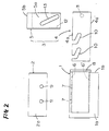
- Fig. 2 is an exploded plan view showing the low insertion force connector of Fig. 1.
- Fig. 3 is a front view showing one connector housing of Fig. 1.
- Fig. 4 is a plan view showing a mutually fitted state of the connector housings of Fig. 1.
- Fig. 5 is a view for explaining the fitting stroke of the connector housings of Fig. 1.
- Fig. 6 is a view for explaining the stroke of a movable member of Fig. 1.
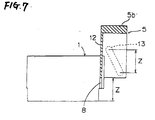
- Fig. 7 is a view for explaining the stroke of an operating member of Fig. 1.
- Fig. 8 is an exploded perspective view showing a conventional low insertion force connector assembly.
- Fig. 9 is a view for explaining an initial state of fitting of the connector assembly of Fig. 8.
- Fig. 10 is a view for explaining a state of completion of the fitting of the connector assembly of Fig. 9.
- Fig. 11 is a perspective view showing another conventional connector assembly.
- Fig. 1 is a plan view showing an embodiment of the low insertion force connector A according to the present invention and Fig. 2 is an exploded plan view showing the same embodiment.
- the low insertion force connector A includes a pair of connector housings 1 and 2 to be mutually fitted, and a fitting guide member 3 attached to the connector housing 1.
- the fitting guide member 3 includes a movable member 4 and an operating member 5.
- the pair of connector housings 1 and 2 each of which has a plurality of built-in terminal metal fittings (not shown) are configured so that the terminal metal fittings are fitted to each other to perform connection of an electric circuit when the connector housings 1 and 2 are fitted to each other.
- guide grooves 6 and 6' to which the movable member 4 is movably attached are formed so as to extend in the direction substantially perpendicular to the direction for mutually fitting the connector housings 1 and 2 as shown in Fig 3.
- Lead-in openings 7 and 7 are formed side by side in the guide groove 6.
- a guide groove 8 is formed in a side wall 1b.
- Cam projections 9 and 9 are provided on an outer wall 2a of the connector housing 2 at positions corresponding to the lead-in openings 7 and 7 respectively.
- the movable member 4 is formed in a strip-like flat plate, and has cam slots 10 and 10 which are engageable with the cam projections 9 and 9 of the connector housing 2 and a cam follower 11 formed at its end portion so as to project downward.
- a lead-in projection 12 is provided on a side edge portion of a rectangular base plate portion 5a and an operating portion 5b is provided on one end of the operating member 5.
- a driving cam slot 13 is formed in the base plate portion 5a.
- the connector housing 2 is fitted into a hood portion 1c of the connector housing 1 on which the movable member 4 and the operating member 5 have been attached. At this time, the cam projections 9 and 9 of the connector housing 2 are engaged into the cam slots 10 and 10 of the movable member 4 from the lead-in openings 7 and 7 of the connector housing 1.
- the connector housings 1 and 2 when the mutual fitting of the connector housings 1 and 2 is to be released, if the operating member 5 is drawn back in the opposite direction (in the direction opposite to that of the arrow P), the connector housings 1 and 2 can be easily separated from each other.
- the movable member by the operation to push the operating member of the fitting guide member to go ahead in the fitting direction, the movable member is moved in the direction substantially perpendicular to the fitting direction of the connector housings. Accordingly, no large operation space is required in the periphery of the connector housings, so that the workability in a narrow space as well as the freedom of arrangement of wires led out from the connector housings are improved. Further, the stroke of the cam slot can be set in two stages, that is, the strokes of the movable member and the fitting guide member so that the insertion force can be set to a largely reduced value. Thus, the present invention has many advantages.
Landscapes
- Details Of Connecting Devices For Male And Female Coupling (AREA)
Applications Claiming Priority (2)
| Application Number | Priority Date | Filing Date | Title |
|---|---|---|---|
| JP107602/96 | 1996-04-26 | ||
| JP08107602A JP3107148B2 (ja) | 1996-04-26 | 1996-04-26 | 低挿入力コネクタ |
Publications (1)
| Publication Number | Publication Date |
|---|---|
| EP0803938A1 true EP0803938A1 (fr) | 1997-10-29 |
Family
ID=14463338
Family Applications (1)
| Application Number | Title | Priority Date | Filing Date |
|---|---|---|---|
| EP97106923A Withdrawn EP0803938A1 (fr) | 1996-04-26 | 1997-04-25 | Connecteur à force d'insertion faible |
Country Status (3)
| Country | Link |
|---|---|
| US (1) | US5816833A (fr) |
| EP (1) | EP0803938A1 (fr) |
| JP (1) | JP3107148B2 (fr) |
Cited By (1)
| Publication number | Priority date | Publication date | Assignee | Title |
|---|---|---|---|---|
| DE10153475A1 (de) * | 2001-10-30 | 2003-05-22 | Delphi Tech Inc | Elektrischer Verbinder |
Families Citing this family (8)
| Publication number | Priority date | Publication date | Assignee | Title |
|---|---|---|---|---|
| JP3638070B2 (ja) * | 1996-12-26 | 2005-04-13 | 矢崎総業株式会社 | J/bのコネクタ接続構造 |
| JP3309368B2 (ja) * | 1997-01-08 | 2002-07-29 | 矢崎総業株式会社 | Lifコネクタ |
| JP3309367B2 (ja) * | 1997-01-08 | 2002-07-29 | 矢崎総業株式会社 | Lifコネクタ |
| JP3384527B2 (ja) * | 1997-01-08 | 2003-03-10 | 矢崎総業株式会社 | Lifコネクタ |
| JP3865278B2 (ja) * | 1998-03-11 | 2007-01-10 | 矢崎総業株式会社 | 自動車ドア用コネクタの接続構造 |
| JP4770405B2 (ja) * | 2005-11-09 | 2011-09-14 | パナソニック株式会社 | 超音波診断装置用コネクタ |
| US7416426B2 (en) * | 2006-01-31 | 2008-08-26 | Fci Americas Technology, Inc. | Push mate assisted electrical connector |
| CN103225729B (zh) * | 2013-05-17 | 2015-11-04 | 四川长虹空调有限公司 | 家用电器支架及其滑动支架安装方法 |
Citations (1)
| Publication number | Priority date | Publication date | Assignee | Title |
|---|---|---|---|---|
| JPH0660933A (ja) * | 1992-08-06 | 1994-03-04 | Yazaki Corp | 低挿抜力多極コネクタ |
Family Cites Families (5)
| Publication number | Priority date | Publication date | Assignee | Title |
|---|---|---|---|---|
| US4586771A (en) * | 1985-03-04 | 1986-05-06 | Amp Incorporated | Connector assembly having camming system for mating and unmating |
| GB8823738D0 (en) * | 1988-10-10 | 1988-11-16 | Amp Italia | Latching mechanism for plug & socket type electrical connector |
| JPH07120541B2 (ja) * | 1990-11-30 | 1995-12-20 | 矢崎総業株式会社 | 嵌合操作用カム部材付きコネクタ |
| JPH07120540B2 (ja) * | 1990-11-30 | 1995-12-20 | 矢崎総業株式会社 | 嵌合操作用カム部材付きコネクタ |
| EP0722203B1 (fr) * | 1995-01-16 | 2003-04-16 | Molex Incorporated | Ensemble d'un connecteur électrique avec un système de came améliorée |
-
1996
- 1996-04-26 JP JP08107602A patent/JP3107148B2/ja not_active Expired - Fee Related
-
1997
- 1997-04-25 EP EP97106923A patent/EP0803938A1/fr not_active Withdrawn
- 1997-04-25 US US08/840,696 patent/US5816833A/en not_active Expired - Fee Related
Patent Citations (1)
| Publication number | Priority date | Publication date | Assignee | Title |
|---|---|---|---|---|
| JPH0660933A (ja) * | 1992-08-06 | 1994-03-04 | Yazaki Corp | 低挿抜力多極コネクタ |
Non-Patent Citations (1)
| Title |
|---|
| PATENT ABSTRACTS OF JAPAN vol. 18, no. 290 (E - 1557) 2 June 1994 (1994-06-02) * |
Cited By (1)
| Publication number | Priority date | Publication date | Assignee | Title |
|---|---|---|---|---|
| DE10153475A1 (de) * | 2001-10-30 | 2003-05-22 | Delphi Tech Inc | Elektrischer Verbinder |
Also Published As
| Publication number | Publication date |
|---|---|
| JP3107148B2 (ja) | 2000-11-06 |
| US5816833A (en) | 1998-10-06 |
| JPH09293559A (ja) | 1997-11-11 |
Similar Documents
| Publication | Publication Date | Title |
|---|---|---|
| US6132231A (en) | Lock device for electrical connector | |
| EP0698940B1 (fr) | Câblage des réseau pour une boíte connecteur électrique, méthode et dispositif pour former un tel réseau | |
| US5816833A (en) | Low insertion force connector | |
| US6050838A (en) | Connector housing having temporary locking mechanism for reciprocatingly engaging with another connector housing | |
| US5791920A (en) | PC card electrical connector | |
| DE102018216917A1 (de) | Stecker | |
| JPH04319271A (ja) | スライド嵌合型電気コネクタ | |
| EP0827237A1 (fr) | Connecteur à force d'insertion faible | |
| US6093040A (en) | Terminal housing connecting structure | |
| KR20120089759A (ko) | 슬라이드 스위치 | |
| EP0898335A2 (fr) | Assemblage de connecteur électrique équipé de moyens pour l'accouplement simultanée de fiche et douille | |
| EP0506075A2 (fr) | Structure de montage d'une pièce d'écartement pour un connecteur | |
| JP3467373B2 (ja) | コネクタの嵌合構造 | |
| KR100295232B1 (ko) | 스위치를갖는시프트노브의구조 | |
| JP4467135B2 (ja) | 筐体連結構造 | |
| US4506440A (en) | Wiring tool for wiring electric multi-pin plug-in connectors, connector strips or the like using clamp-cutting techniques | |
| US6129567A (en) | Connector assembly having an actuating slide | |
| US4050759A (en) | Zero-insertion-withdrawal force connector | |
| KR910004228Y1 (ko) | 다단식 푸쉬버튼 스위치 | |
| US4725702A (en) | Miniature switch with self-aligning movable contactor | |
| JPH0582215A (ja) | 零挿入力コネクタ | |
| US4386251A (en) | Fixture for push-button switch | |
| JPS61198582A (ja) | 直線動作コネクタ | |
| KR100679276B1 (ko) | 로킹타입의 푸쉬버턴스위치 | |
| EP4691749A1 (fr) | Dispositif de sertissage hexagonal avec vilebrequin |
Legal Events
| Date | Code | Title | Description |
|---|---|---|---|
| PUAI | Public reference made under article 153(3) epc to a published international application that has entered the european phase |
Free format text: ORIGINAL CODE: 0009012 |
|
| AK | Designated contracting states |
Kind code of ref document: A1 Designated state(s): BE DE FR GB SE |
|
| 17P | Request for examination filed |
Effective date: 19971215 |
|
| 17Q | First examination report despatched |
Effective date: 20020404 |
|
| STAA | Information on the status of an ep patent application or granted ep patent |
Free format text: STATUS: THE APPLICATION IS DEEMED TO BE WITHDRAWN |
|
| 18D | Application deemed to be withdrawn |
Effective date: 20020815 |