EP0803944A2 - Article comprenant un amplificateur hybride à plusieurs étages à fibre optique - Google Patents
Article comprenant un amplificateur hybride à plusieurs étages à fibre optique Download PDFInfo
- Publication number
- EP0803944A2 EP0803944A2 EP97302411A EP97302411A EP0803944A2 EP 0803944 A2 EP0803944 A2 EP 0803944A2 EP 97302411 A EP97302411 A EP 97302411A EP 97302411 A EP97302411 A EP 97302411A EP 0803944 A2 EP0803944 A2 EP 0803944A2
- Authority
- EP
- European Patent Office
- Prior art keywords
- fiber
- amplifier
- multistage
- pump radiation
- stage
- Prior art date
- Legal status (The legal status is an assumption and is not a legal conclusion. Google has not performed a legal analysis and makes no representation as to the accuracy of the status listed.)
- Granted
Links
- 239000013307 optical fiber Substances 0.000 title claims description 20
- 239000000835 fiber Substances 0.000 claims abstract description 68
- 229910052761 rare earth metal Inorganic materials 0.000 claims abstract description 13
- 229910052691 Erbium Inorganic materials 0.000 claims abstract 2
- 230000005855 radiation Effects 0.000 claims description 36
- 238000001228 spectrum Methods 0.000 claims description 23
- VYPSYNLAJGMNEJ-UHFFFAOYSA-N Silicium dioxide Chemical compound O=[Si]=O VYPSYNLAJGMNEJ-UHFFFAOYSA-N 0.000 claims description 14
- 238000004891 communication Methods 0.000 claims description 10
- 230000003595 spectral effect Effects 0.000 claims description 9
- 230000003287 optical effect Effects 0.000 claims description 8
- 239000000377 silicon dioxide Substances 0.000 claims description 7
- 229910052769 Ytterbium Inorganic materials 0.000 claims description 4
- 229910052693 Europium Inorganic materials 0.000 claims description 2
- 229910052688 Gadolinium Inorganic materials 0.000 claims description 2
- 229910052746 lanthanum Inorganic materials 0.000 claims description 2
- 230000005540 biological transmission Effects 0.000 claims 3
- 230000015556 catabolic process Effects 0.000 abstract description 2
- 238000006731 degradation reaction Methods 0.000 abstract description 2
- 102100027004 Inhibin beta A chain Human genes 0.000 description 5
- 150000002500 ions Chemical class 0.000 description 5
- 150000002910 rare earth metals Chemical class 0.000 description 4
- 208000022673 Distal myopathy, Welander type Diseases 0.000 description 2
- 208000034384 Welander type distal myopathy Diseases 0.000 description 2
- 238000009738 saturating Methods 0.000 description 2
- 230000002269 spontaneous effect Effects 0.000 description 2
- 230000001629 suppression Effects 0.000 description 2
- PNEYBMLMFCGWSK-UHFFFAOYSA-N aluminium oxide Inorganic materials [O-2].[O-2].[O-2].[Al+3].[Al+3] PNEYBMLMFCGWSK-UHFFFAOYSA-N 0.000 description 1
- 238000013459 approach Methods 0.000 description 1
- 238000006243 chemical reaction Methods 0.000 description 1
- 238000005253 cladding Methods 0.000 description 1
- 229910052681 coesite Inorganic materials 0.000 description 1
- 229910052593 corundum Inorganic materials 0.000 description 1
- 230000008878 coupling Effects 0.000 description 1
- 238000010168 coupling process Methods 0.000 description 1
- 238000005859 coupling reaction Methods 0.000 description 1
- 229910052906 cristobalite Inorganic materials 0.000 description 1
- 230000001419 dependent effect Effects 0.000 description 1
- 238000013461 design Methods 0.000 description 1
- 238000002474 experimental method Methods 0.000 description 1
- 230000004927 fusion Effects 0.000 description 1
- 238000000034 method Methods 0.000 description 1
- 238000005086 pumping Methods 0.000 description 1
- 239000000523 sample Substances 0.000 description 1
- 229920006395 saturated elastomer Polymers 0.000 description 1
- 239000004065 semiconductor Substances 0.000 description 1
- 235000012239 silicon dioxide Nutrition 0.000 description 1
- 229910052682 stishovite Inorganic materials 0.000 description 1
- 238000006467 substitution reaction Methods 0.000 description 1
- 238000012360 testing method Methods 0.000 description 1
- 229910052905 tridymite Inorganic materials 0.000 description 1
- 229910001845 yogo sapphire Inorganic materials 0.000 description 1
Images


Classifications
-
- H—ELECTRICITY
- H01—ELECTRIC ELEMENTS
- H01S—DEVICES USING THE PROCESS OF LIGHT AMPLIFICATION BY STIMULATED EMISSION OF RADIATION [LASER] TO AMPLIFY OR GENERATE LIGHT; DEVICES USING STIMULATED EMISSION OF ELECTROMAGNETIC RADIATION IN WAVE RANGES OTHER THAN OPTICAL
- H01S3/00—Lasers, i.e. devices using stimulated emission of electromagnetic radiation in the infrared, visible or ultraviolet wave range
- H01S3/05—Construction or shape of optical resonators; Accommodation of active medium therein; Shape of active medium
- H01S3/06—Construction or shape of active medium
- H01S3/063—Waveguide lasers, i.e. whereby the dimensions of the waveguide are of the order of the light wavelength
- H01S3/067—Fibre lasers
- H01S3/06754—Fibre amplifiers
- H01S3/06758—Tandem amplifiers
-
- H—ELECTRICITY
- H01—ELECTRIC ELEMENTS
- H01S—DEVICES USING THE PROCESS OF LIGHT AMPLIFICATION BY STIMULATED EMISSION OF RADIATION [LASER] TO AMPLIFY OR GENERATE LIGHT; DEVICES USING STIMULATED EMISSION OF ELECTROMAGNETIC RADIATION IN WAVE RANGES OTHER THAN OPTICAL
- H01S2301/00—Functional characteristics
- H01S2301/04—Gain spectral shaping, flattening
-
- H—ELECTRICITY
- H01—ELECTRIC ELEMENTS
- H01S—DEVICES USING THE PROCESS OF LIGHT AMPLIFICATION BY STIMULATED EMISSION OF RADIATION [LASER] TO AMPLIFY OR GENERATE LIGHT; DEVICES USING STIMULATED EMISSION OF ELECTROMAGNETIC RADIATION IN WAVE RANGES OTHER THAN OPTICAL
- H01S3/00—Lasers, i.e. devices using stimulated emission of electromagnetic radiation in the infrared, visible or ultraviolet wave range
- H01S3/14—Lasers, i.e. devices using stimulated emission of electromagnetic radiation in the infrared, visible or ultraviolet wave range characterised by the material used as the active medium
- H01S3/16—Solid materials
- H01S3/1601—Solid materials characterised by an active (lasing) ion
- H01S3/1603—Solid materials characterised by an active (lasing) ion rare earth
- H01S3/1608—Solid materials characterised by an active (lasing) ion rare earth erbium
-
- H—ELECTRICITY
- H01—ELECTRIC ELEMENTS
- H01S—DEVICES USING THE PROCESS OF LIGHT AMPLIFICATION BY STIMULATED EMISSION OF RADIATION [LASER] TO AMPLIFY OR GENERATE LIGHT; DEVICES USING STIMULATED EMISSION OF ELECTROMAGNETIC RADIATION IN WAVE RANGES OTHER THAN OPTICAL
- H01S3/00—Lasers, i.e. devices using stimulated emission of electromagnetic radiation in the infrared, visible or ultraviolet wave range
- H01S3/14—Lasers, i.e. devices using stimulated emission of electromagnetic radiation in the infrared, visible or ultraviolet wave range characterised by the material used as the active medium
- H01S3/16—Solid materials
- H01S3/1601—Solid materials characterised by an active (lasing) ion
- H01S3/1603—Solid materials characterised by an active (lasing) ion rare earth
- H01S3/1618—Solid materials characterised by an active (lasing) ion rare earth ytterbium
Definitions
- This invention pertains to Er-doped optical fiber amplifiers, and to optical fiber communication systems that comprise such fiber amplifiers.
- Er-doped fiber amplifiers are well known, as are optical fiber communication systems that comprise one or more EDFAs.
- EDFAs Er-doped fiber amplifiers
- the amplifier we refer to the amplifier as well as to the systems that comprise one or more amplifiers as "articles" that comprise an amplifier.
- single stage EDFAs will frequently not be able to provide the required performance characteristics.
- a single stage EDFA will frequently not be able to deliver the required high output power and spectral gain flatness.
- a single stage EDFA we mean an EDFA containing a length of a single Er-doped fiber (EDF) of longitudinally essentially constant composition
- a “multistage” EDFA we mean an EDFA having two or more serially connected non-identical EDFs. The latter may also be referred to as a "hybrid" multistage EDFA.
- the European patent application discloses a fiber amplifier that contains at least two kinds of serially coupled rare earth doped optical fibers.
- the rare earth element present in both kinds of fibers preferably is Er, and the serially coupled fibers differ with regard to Al 2 O 3 concentration, P 2 O 5 concentration, Er doping concentration, or a combination of these.
- the first (input) stage of the prior art hybrid EDFA typically is an EDF codoped with Al
- the second (output) stage typically is an EDF codoped with P and Al. Both stages typically are pumped with radiation of the same wavelength.
- the above referenced ECOC '95 paper discloses the results of a WDM experiment with four channels (1548, 1552, 1555 and 1558 nm).
- Average gain of the prior art 2-stage EDFA was reported to be 26 dB, with maximum gain difference among the 4 channels said to have been 0.3 dB.
- Total output power of 10 dBm, and noise figure (NF) ⁇ 6.8 dB were reported.
- EDFs codoped with P and Yb are known. See, for instance, J. Townsend et al., Electronics Letters, Vol. 27, p. 1958 (1991), and S. Grubb et al., Proceedings of OFC '96, paper TuG4, p. 30.
- An Er- and Yb-doped optical amplifier fiber is frequently referred to as an "EYDFA".
- the invention is defined by the claims. In a broad aspect it is embodied in a novel multistage EDFA, and in an optical fiber communication system that comprises the EDFA.
- the EDFA comprises an input stage and an output stage serially coupled to the former.
- the input stage comprises a first silica-based (i.e., more than 50 atomic % SiO 2 ) EDF doped with Al
- the output stage comprises a second silica-based EDF.
- the EDFA furthermore comprises means for providing pump radiation to the first and second EDFs.
- the second EDF further comprises at least one rare earth (atomic number 57-71) element other than Er, preferably selected from the group consisting of Lu, Ce, La, Gd, Eu and Yb, most preferably Yb.
- the concentration of the further rare earth element typically is greater (frequently at least 5 times greater) than the Er concentration in the second EDF.
- the second EDF optionally also comprises Al and/or P.
- the means for providing pump radiation to the second EDF advantageously are adapted for providing radiation in the wavelength range 900-1100 nm (e.g., 1064 nm).
- the means for providing pump radiation to the second EDF typically will be adapted for providing radiation in the range 950-1000 nm, or 1450-1500 nm.
- the means adapted for providing pump radiation to the first EDF will be adapted for providing radiation in the wavelength range 950-1000 nm (e.g., 980 nm) or for providing radiation in the range 1450-1500 nm (e.g., 1480 nm).
- the first and second EDFs and the pump radiations are typically selected such that the multistage EDFA has substantially flat gain (e.g., gain variation at most about 1 dB) over a spectral region that extends over at least 15 nm. In some preferred embodiments that spectral region extends to wavelengths above 1560 nm, thereby meeting a current requirement for at least some WDM systems.
- multistage EDFAs according to the invention can be designed to have a wider flat gain region (e.g., 1544 to 1562 nm) than typically is obtained with prior art multistage EDFAs. Furthermore, EDFAs according to the invention can be designed to provide higher output power, without significant degradation of the noise figure, than prior art multistage EDFAs. Indeed, a multistage EDFA according to the invention, with an EDF co-doped with Yb (and P for enhanced power conversion) in the output stage, can have substantially higher output power (e.g., > 4W) than a corresponding Yb - free EDFA (typically having at most about 300 mW output power).
- the flat gain region of a 2-stage EDFA with P-doped output stage is not much wider than that of a corresponding P-free EDFA, and in both cases does not extend above 1560 nm, whereas a 2-stage EDFA according to the invention, with Yb-doped second EDF, can have a wider flat gain region than the prior art EDFA with P-doped output stage, with the flat gain region extending above 1560 nm.
- the relatively wide flat gain region of the Yb-containing multistage EDFA according to the invention is obtained despite the fact that the gain of Er- and Yb-doped fiber is not flat over the wavelength region of interest.
- a further advantage that can be provided by a multistage EDFA according to the invention is suppression of amplifier gain for wavelengths less than about 1540 nm. This is desirable because gain in this wavelength range can increase amplified spontaneous emission (ASE) radiation, resulting in increased noise figure (NF) of the amplifier, and/or in reduced power output.
- ASE amplified spontaneous emission
- NF noise figure
- Yb-containing multistage EDFAs according to the invention can have low NF despite the fact that the NF of Er- and Yb-doped fiber is not particularly low. This advantageous result is a consequence of the fact that the NF of a multistage amplifier is substantially determined by the NF of the input stage.
- multistage EDFAs according to the invention can have a relatively low NF, a relatively flat gain spectrum that can extend above 1560 nm, and can (at least in some embodiments, e.g., embodiments with Yb-doped second fiber that are pumped at about 1064 nm) have high output power.
- Other embodiments, e.g., those with Lu-doped second fiber can have similarly low NF and flat gain spectrum, but typically have lower output power, due to the unavailability of a convenient very high power pump radiation source in the relevant wavelength range (exemplarily 950-1010 nm).
- the latter embodiments can conveniently use known semiconductor laser diodes as pump sources in both stages, and this is considered to be a significant advantage in at least some applications.
- multistage EDFAs according to the invention are contemplated.
- optical fiber communication systems e.g., WDM or analog CATV
- multistage EDFAs according to the invention with or without pump radiation sources, and with or without conventional components such as filters and isolators, are also likely to become themselves articles of commerce.
- the fibers used in the practice of the invention typically are silica-based fibers with germanium- and Er-doped core surrounded by a pure silica or F-doped silica cladding.
- the core furthermore typically contains Al
- in the second amplifier fiber contains Yb or other rare earth element, and optionally contains P.
- Techniques for making such fibers are well known and do not require recitation.
- the input stage (first) fiber contained about 150 molar ppm (parts per million) Er ions/Si ions, 6.4 molar % Al, had N.A.
- the output stage (second) fiber had about 1400 molar ppm Er ions/Si ions, 8 molar % P, 2 molar % Al, 2 molar % Ge, and 14 times as much Yb as Er, all concentrations pertaining to the fiber core.
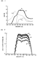
- FIGs. 1 and 2 show the measured gain (when all Er-ions are inverted) (10, 20) and loss (when all Er-ions are uninverted) (11, 21) for the above described first and second fibers, respectively.
- FIGs. 3 and 4 show calculated gain per unit length as a function of wavelength for the above described first and second fibers, respectively.
- numerals 30-39, 391 refer to gain spectra for 100, 95, 90, 85, 80, 75, 70, 65, 60, 55 and 50% inversion, respectively.
- numerals 40-49, 491-493 refer to gain spectra for 100, 95, 90, 85, 80, 75, 70, 65, 60, 55, 50, 45 and 40% inversion, respectively.
- the first fiber has a somewhat flatter gain spectrum than the second, but neither fiber by itself is adequate for some demanding applications, e.g., analog CATV.
- FIG. 5 shows the computed gain spectrum of 15 m of the first fiber (100% inversion) series-connected to 6m of the second fiber (47% inversion).
- the gain spectrum of the combination is substantially flat ( ⁇ 0.5 dB) over a wavelength range of about 17 nm, with a gain of about 32 dB.
- both fibers could be shortened or lengthened by the same percentage. For instance, 10 m and 4 m of the respective fibers (with same inversions) would produce 22 dB of gain, substantially flat over a 17 nm range.
- FIG. 7 shows further calculated exemplary gain spectra.
- Numeral 72 refers to the spectrum of 15 m of the first fiber, 98% inverted, numeral 71 to the spectrum of a 9 m of the second fiber, 48% inverted, numeral 70 to the spectrum of the combination of the two fibers, and numeral 73 to the best spectrum of the second fiber alone (18.6 m, 51% inverted).
- the input stage of a multistage amplifier according to the invention can have advantageously low NF, exemplarily ⁇ 4 dB (excluding losses due to components such as isolators, WDMs, pump reflectors and splices).
- the input power to the output stage frequently is high enough to substantially saturate the gain of the output stage and reduce the output stage inversion to about 50%, substantially as suggested by the calculated results.
- the above describe first and second fibers are possible choices for a substantially optimized multistage EDFA according to the invention.
- Such a design can have advantageously low NF and high power output, especially if the output stage is pumped with high intensity radiation of about 1064 nm wavelength.
- FIG. 9 shows the flattest gain spectra obtainable for different 2-stage 30-dB EDFAs.
- Curve 90 pertains to an amplifier having the same Al-doped EDF (6.4% Al) in both stages.
- Curve 91 pertains to an amplifier having Al-doped EDF in the input stage and P-doped EDF in the output stage; and
- curve 92 pertains to an amplifier according to the invention, with Al-doped EDF in the input stage and Yb and P-doped EDF in the output stage.
- the flat spectral region of the EDFA according to the invention is shifted upward in wavelength. as compared to the prior art EDFA (91). This desirable feature enables placement of a channel at longer wavelengths, where the NF is lower than at shorter wavelengths.
- the EDFA according to the invention has flatter gain over a wider spectral region than does the prior art EDFA (91).
- FIG. 6 schematically depicts an exemplary 2-stage EDFA (60) according to the invention.
- Input radiation e.g., about 1550 nm radiation
- WDM wavelength-dependent coupler
- Pump radiation e.g., 980 nm radiation from a known laser diode 691
- the signal radiation is amplified in EDF 63, and propagates through (optional) pump radiation reflector 64 and (optional) optical isolator 65 to WDM 66 and second EDF 67.
- WDM 66 Radiation from pump laser 692 (e.g., a known Nd-doped fiber laser emitting 1064 nm radiation) is coupled into the second EDF by means of WDM 66. Finally amplified signal radiation propagates through (optional) WDM 68 and (optional) optical isolator 69 and is available for coupling into a conventional optical fiber or for provision to other conventional utilization means, e.g., a multi-channel splitter. Optional WDM 68 serves to remove remnant pump power from the signal path.
- the "X" symbols (e.g., 693) indicate in conventional fashion fiber connections, typically fused fiber splices.
- the invention can be embodied in amplifiers having a variety of configurations.
- a variety of pumping arrangements can be used, including co-propagating, counter-propagating and dual-propagating (co- and counter-propagating) pump radiation in either or both stages.
- all pump wavelengths useful for the first EDF e.g., 950-1000 nm, typically about 980 nm; 1450-1500 nm, typically about 1480 nm
- all pump wavelengths useful for the second EDF e.g., 900-1100 nm, exemplarily about 980 or 1064 nm; 1450-1500 nm
- multistage amplifiers having more than two stages e.g., to a multistage amplifier having two first fiber stages and one second fiber stage, to one having one first fiber stage and two second fiber stages, or to one having two first fiber stages and two second fiber stages.
- Passive components such as filters, isolators or WDMs can be incorporated into a multistage amplifier according to the invention in any desired way, in accordance with specific performance requirements. For instance, there need not be any passive component between the first fiber and the second fiber, and two dissimilar fibers could be directly jointed together.
- amplifiers according to the invention can be operated at inversion levels other than the above discussed levels, as well as at all desired input power levels and output power levels.
- the first fiber is pumped such that the inversion level is above 50%
- the second fiber is pumped such that the inversion level is in the range 25-75%.
- FIG. 11 schematically depicts an exemplary optical fiber communication system (110) according to the invention, more specifically, an analog CATV system.
- reference numerals 111-114 refer, respectively, to a transmitter (receiving n electrical inputs that are used to amplitude-modulate the output of a laser), the optical output of the transmitter, a length of conventional optical fiber, and a conventional fiber joint, e.g., a fusion splice.
- Multistage amplifier 115 exemplarily is a 2-stage amplifier substantially as shown in Fig. 6, and 1xN splitter 116 divides the amplified signal into N signals which are distributed to N receivers 1171-117N, respectively.
- a 2-stage optical fiber amplifier substantially as shown in FIG. 6, was assembled.
- the input stage contained 15 m of the above-described first fiber, and the output stage contained 9 m of the above-described second fiber.
- the first fiber was pumped with 100 mW of 980 nm radiation from a conventional single stripe laser diode.
- a known pump reflector was provided to enhance inversion of the Er ions in the first fiber.
- a conventional optical isolator was placed between the two stages to suppress backward-traveling amplified spontaneous emission.
- the total component loss was about 6dB, with a slope of about 0.05 dB/nm. Because of the wavelength dependence of the total component loss the inversion in the second fiber was somewhat reduced, with consequent reduction of output power.
- a saturating tone was provided at 1548 nm, and its power adjusted to various levels. A small probe signal was added and swept across the spectrum to measure gain. For each saturating tone level, the pump power of the output stage was adjusted until the flattest spectrum was achieved. Exemplary results are shown in FIG. 8.
- All four spectra of FIG. 8 achieved more than 17 nm bandwidth, with as little as 0.4 dB variation in one case.
- the 1064 nm output stage pump power levels for these cases were 307, 425, 645 and 1024 mW for -15, -11, -7 and -3 dBm signal inputs, respectively, corresponding to curves 80-83, respectively.
- the measured output power at 1548 nm was 14.53, 18.01, 21.06 and 23.61 of dBm for -15, -11, -7 and -3 dBm signals, respectively.
- FIG. 10 shows exemplary results, with curves 100 and 101 pertaining to -17 and -1 dBm, respectively. As can be seen, the output power varies only slightly, indicative of a highly saturated amplifier.
- the second fiber was lengthened to 12 m, and optimized for flatness substantially as described.
- the output power increased by 5.4 dB for all signal levels to 19.93, 23.41, 26.46 dBm for -15, -11, -7 dBm signals, respectively.
- the flatness was slightly worse than shown in FIG. 7, with the variation increasing by about 0.3 dB across the 17 nm spectral range.
- the NF of multistage amplifiers according to the invention is substantially determined by the NF of the input stage. Including pre-amplifier loss, the NF at 1548 nm of the 2-stage amplifier of Example 1 was under 5 dB for all cases, with a minimum of about 4.2 dB for the smallest signal case.
Landscapes
- Physics & Mathematics (AREA)
- Electromagnetism (AREA)
- Engineering & Computer Science (AREA)
- Plasma & Fusion (AREA)
- Optics & Photonics (AREA)
- Lasers (AREA)
Applications Claiming Priority (2)
| Application Number | Priority Date | Filing Date | Title |
|---|---|---|---|
| US635833 | 1984-07-30 | ||
| US63583396A | 1996-04-22 | 1996-04-22 |
Publications (3)
| Publication Number | Publication Date |
|---|---|
| EP0803944A2 true EP0803944A2 (fr) | 1997-10-29 |
| EP0803944A3 EP0803944A3 (fr) | 1998-09-02 |
| EP0803944B1 EP0803944B1 (fr) | 2001-07-11 |
Family
ID=24549293
Family Applications (1)
| Application Number | Title | Priority Date | Filing Date |
|---|---|---|---|
| EP97302411A Expired - Lifetime EP0803944B1 (fr) | 1996-04-22 | 1997-04-08 | Amplificateur hybride à plusieurs étages à fibre optique et système de communication comprenant ledit amplificateur |
Country Status (4)
| Country | Link |
|---|---|
| US (1) | US5731892A (fr) |
| EP (1) | EP0803944B1 (fr) |
| JP (1) | JP3670434B2 (fr) |
| DE (1) | DE69705580T2 (fr) |
Cited By (7)
| Publication number | Priority date | Publication date | Assignee | Title |
|---|---|---|---|---|
| GB2331621A (en) * | 1997-11-20 | 1999-05-26 | Samsung Electronics Co Ltd | An optical fibre amplifier |
| EP0982817A1 (fr) * | 1998-08-27 | 2000-03-01 | Alcatel | Fibre optique à usage d'amplificateur optique avec une gaine dopée au fluor |
| WO2001011735A1 (fr) * | 1999-08-04 | 2001-02-15 | Mitsubishi Cable Industries, Ltd. | Amplificateur optique |
| EP1089401A1 (fr) * | 1999-09-29 | 2001-04-04 | Optical Technologies U.S.A. Corp. | Amplificateur optique et système de transmission optique |
| US6246515B1 (en) | 1998-12-18 | 2001-06-12 | Corning Incorporated | Apparatus and method for amplifying an optical signal |
| US6556346B1 (en) | 1998-09-22 | 2003-04-29 | Corning O.T.I.Spa | Optical amplifying unit and optical transmission system |
| US6603598B1 (en) | 1999-09-29 | 2003-08-05 | Corning O.T.I. Inc. | Optical amplifying unit and optical transmission system |
Families Citing this family (29)
| Publication number | Priority date | Publication date | Assignee | Title |
|---|---|---|---|---|
| US6512879B1 (en) * | 1997-01-14 | 2003-01-28 | Corning Incorporated | Glass composition and optical device made therefrom |
| FR2758321A1 (fr) * | 1997-01-14 | 1998-07-17 | Corning Inc | Composition de verre et dispositif optique |
| US5920424A (en) * | 1997-02-18 | 1999-07-06 | Lucent Technologies Inc. | Article comprising a broadband optical fiber amplifier |
| JP3621220B2 (ja) * | 1997-03-17 | 2005-02-16 | 富士通株式会社 | 光増幅器及び光導波構造 |
| US5815518A (en) * | 1997-06-06 | 1998-09-29 | Lucent Technologies Inc. | Article comprising a cascaded raman fiber laser |
| DE69725840T2 (de) * | 1997-06-06 | 2004-07-22 | Avanex Corp., Fremont | Faseroptisches Telekommunikationssystem |
| US5937134A (en) * | 1997-08-07 | 1999-08-10 | Lucent Technologies Inc. | Cladding pumped fiber lasers |
| JPH11307853A (ja) * | 1998-04-27 | 1999-11-05 | Oki Electric Ind Co Ltd | 光ファイバ増幅器 |
| JP4094126B2 (ja) * | 1998-07-09 | 2008-06-04 | 富士通株式会社 | 希土類ドープ光ファイバ及びそれを用いた光ファイバ増幅器 |
| JP2000106544A (ja) * | 1998-09-28 | 2000-04-11 | Fujitsu Ltd | 光増幅器及び波長多重光伝送システム |
| US6429964B1 (en) * | 1999-09-24 | 2002-08-06 | Agere Systems Guardian Corp. | High power, multiple-tap co-doped optical amplifier |
| US6381063B1 (en) * | 2000-03-16 | 2002-04-30 | Corning Incorporated | Long band optical amplifier |
| EP1340295A2 (fr) * | 2000-11-09 | 2003-09-03 | Bookham Technology PLC | Amplificateur optique et procede d'amplification d'un signal optique |
| US6560009B1 (en) * | 2001-08-21 | 2003-05-06 | Lucent Technologies Inc. | Erbium doped fibers for extended L-band amplification |
| US7440171B2 (en) * | 2002-10-31 | 2008-10-21 | Finisar Corporation | Staged amplifier for lower noise figure and higher saturation power |
| JP2005051196A (ja) * | 2003-07-15 | 2005-02-24 | Furukawa Electric Co Ltd:The | エルビュームドープ光ファイバ増幅器 |
| JP4655553B2 (ja) * | 2003-09-05 | 2011-03-23 | 住友電気工業株式会社 | 光増幅性導波路、光増幅モジュールおよび光通信システム |
| KR100539937B1 (ko) * | 2003-12-04 | 2005-12-28 | 삼성전자주식회사 | 이중 출력 구조의 광대역 광원 |
| JP2009105080A (ja) * | 2006-01-04 | 2009-05-14 | Sumitomo Electric Ind Ltd | 増幅用光ファイバ |
| US7532391B2 (en) * | 2006-01-20 | 2009-05-12 | Sumitomo Electric Industries, Ltd. | Optical amplification module and laser light source designed to suppress photodarkening |
| US8744224B2 (en) * | 2006-03-07 | 2014-06-03 | Alcatel Lucent | Tapered fiber bundle apparatus with monitoring capability |
| US7724423B2 (en) * | 2006-03-16 | 2010-05-25 | Alcatel-Lucent Usa Inc. | Optical fiber laser having improved efficiency |
| US7848014B2 (en) * | 2008-04-09 | 2010-12-07 | Cisco Technology, Inc. | Erbium and Erbium/Ytterbium cladding pumped hybrid optical amplifier |
| JP2009290203A (ja) * | 2008-04-30 | 2009-12-10 | Sumitomo Electric Ind Ltd | 光増幅モジュールおよびレーザ光源装置 |
| JP2012044224A (ja) * | 2011-11-28 | 2012-03-01 | Sumitomo Electric Ind Ltd | 光増幅装置およびレーザ光源装置 |
| PT2947728T (pt) * | 2014-05-23 | 2018-05-02 | Padtec S A | Amplificador óptico, sistema de comunicação óptica wdm e método para amplificar opticamente um sinal óptico wdm |
| JP7149515B2 (ja) * | 2017-07-14 | 2022-10-07 | 国立研究開発法人宇宙航空研究開発機構 | 希土類元素添加光ファイバ、及び希土類元素添加光ファイバの耐放射線性を向上させる方法 |
| GB2598775A (en) * | 2020-09-14 | 2022-03-16 | Coherent Scotland Ltd | 780 nm ultrashort-pulsed fiber laser |
| US12126134B2 (en) | 2021-08-06 | 2024-10-22 | Huawei Technologies Canada Co., Ltd. | Systems and methods to increase pump conversion efficiency of an optical fiber |
Family Cites Families (7)
| Publication number | Priority date | Publication date | Assignee | Title |
|---|---|---|---|---|
| DE4002369A1 (de) * | 1990-01-27 | 1991-08-01 | Standard Elektrik Lorenz Ag | Mehrstufiger faseroptischer verstaerker |
| US5050949A (en) * | 1990-06-22 | 1991-09-24 | At&T Bell Laboratories | Multi-stage optical fiber amplifier |
| US5225925A (en) * | 1991-01-23 | 1993-07-06 | Amoco Corporation | Sensitized erbium fiber optical amplifier and source |
| US5234104A (en) * | 1991-02-04 | 1993-08-10 | Illinois Tool Works Inc. | Carrier tape system |
| JP2636152B2 (ja) * | 1993-11-24 | 1997-07-30 | 住友電気工業株式会社 | 光ファイバ増幅器および光通信システム |
| JPH07264231A (ja) * | 1994-03-16 | 1995-10-13 | Fujitsu Ltd | 回線切替え方式 |
| US5594747A (en) * | 1995-03-06 | 1997-01-14 | Ball; Gary A. | Dual-wavelength pumped low noise fiber laser |
-
1997
- 1997-03-11 JP JP05591697A patent/JP3670434B2/ja not_active Expired - Lifetime
- 1997-04-08 EP EP97302411A patent/EP0803944B1/fr not_active Expired - Lifetime
- 1997-04-08 DE DE69705580T patent/DE69705580T2/de not_active Expired - Lifetime
- 1997-04-22 US US08/847,766 patent/US5731892A/en not_active Expired - Lifetime
Cited By (9)
| Publication number | Priority date | Publication date | Assignee | Title |
|---|---|---|---|---|
| GB2331621A (en) * | 1997-11-20 | 1999-05-26 | Samsung Electronics Co Ltd | An optical fibre amplifier |
| GB2331621B (en) * | 1997-11-20 | 2000-07-05 | Samsung Electronics Co Ltd | Optical fiber amplifier |
| EP0982817A1 (fr) * | 1998-08-27 | 2000-03-01 | Alcatel | Fibre optique à usage d'amplificateur optique avec une gaine dopée au fluor |
| FR2782807A1 (fr) * | 1998-08-27 | 2000-03-03 | Alsthom Cge Alcatel | Fibre optique a usage d'amplificateur optique avec une gaine dopee au fluor |
| US6556346B1 (en) | 1998-09-22 | 2003-04-29 | Corning O.T.I.Spa | Optical amplifying unit and optical transmission system |
| US6246515B1 (en) | 1998-12-18 | 2001-06-12 | Corning Incorporated | Apparatus and method for amplifying an optical signal |
| WO2001011735A1 (fr) * | 1999-08-04 | 2001-02-15 | Mitsubishi Cable Industries, Ltd. | Amplificateur optique |
| EP1089401A1 (fr) * | 1999-09-29 | 2001-04-04 | Optical Technologies U.S.A. Corp. | Amplificateur optique et système de transmission optique |
| US6603598B1 (en) | 1999-09-29 | 2003-08-05 | Corning O.T.I. Inc. | Optical amplifying unit and optical transmission system |
Also Published As
| Publication number | Publication date |
|---|---|
| US5731892A (en) | 1998-03-24 |
| JP3670434B2 (ja) | 2005-07-13 |
| DE69705580T2 (de) | 2002-06-06 |
| EP0803944A3 (fr) | 1998-09-02 |
| EP0803944B1 (fr) | 2001-07-11 |
| JPH09331091A (ja) | 1997-12-22 |
| DE69705580D1 (de) | 2001-08-16 |
Similar Documents
| Publication | Publication Date | Title |
|---|---|---|
| US5731892A (en) | Article comprising hybrid optical fiber amplifier | |
| JP3936533B2 (ja) | 希土類ドープファイバ増幅器および多段ファイバ増幅器 | |
| JP4900501B2 (ja) | 光増幅器及び光増幅方法 | |
| US6437907B1 (en) | Wide-band optical fiber amplifier and amplifying method thereof | |
| WO2000024094A1 (fr) | Gestion et utilisation de l'emission spontanee amplifiee dans un amplificateur optique | |
| KR100334778B1 (ko) | 피드 백 루프를 이용한 장파장 대역 광섬유 증폭기 | |
| US6529317B2 (en) | L-band erbium-doped fiber amplifier pumped by 1530 nm-band pump | |
| JP2001313433A (ja) | 光増幅器及び光増幅方法 | |
| US6441953B1 (en) | L band multistage amplifier with improved noise figure | |
| KR100277360B1 (ko) | 장파장 광신호에 적합한 어븀 도핑 광섬유증폭기 | |
| US6556342B1 (en) | Thulium doped fiber pump for pumping Raman amplifiers | |
| KR100539877B1 (ko) | 출력 파워들의 독립적인 제어가 가능한 이중 출력 구조를갖는 광대역 광원 | |
| KR100334789B1 (ko) | 피드 백 루프를 이용한 광학 소자 측정용 광대역 광원 | |
| KR100334809B1 (ko) | 씨드-빔을 이용한 광대역 광원 | |
| KR100474714B1 (ko) | 광대역 광섬유 증폭기 | |
| KR100399578B1 (ko) | 장파장 이득대역 어븀 첨가 광섬유 증폭기 및 역방향 진행자연방출광 차단 방법 | |
| JP2002252399A (ja) | 光増幅器 | |
| Choi et al. | Performances of Erbium‐Doped Fiber Amplifier Using 1530nm‐Band Pump for Long Wavelength Multichannel Amplification | |
| KR100341215B1 (ko) | 에르븀첨가광섬유의 장파장대역을 이용한 2단 광증폭기 | |
| Sinivasagam et al. | New pumping scheme for high gain and low noise figure in an erbium-doped fiber amplifier | |
| JPH0728106A (ja) | 光ファイバ増幅器および光信号伝送システム | |
| KR20050060674A (ko) | 직접 펌핑 구조의 광대역 광원 | |
| Smart et al. | Effect of pumping configuration on noise figure and efficiency for 0.98-um-pumped saturated erbium-doped fiber amplifiers | |
| Harun et al. | Gain and noise performances of an L‐band EDFA utilizing a ring laser cavity with fiber Bragg grating | |
| Harun et al. | Gain-clamped L-band erbium-doped fiber amplifier with co-and counter-propagating lasers |
Legal Events
| Date | Code | Title | Description |
|---|---|---|---|
| PUAI | Public reference made under article 153(3) epc to a published international application that has entered the european phase |
Free format text: ORIGINAL CODE: 0009012 |
|
| AK | Designated contracting states |
Kind code of ref document: A2 Designated state(s): DE FR GB IT |
|
| PUAL | Search report despatched |
Free format text: ORIGINAL CODE: 0009013 |
|
| AK | Designated contracting states |
Kind code of ref document: A3 Designated state(s): DE FR GB IT |
|
| 17P | Request for examination filed |
Effective date: 19990218 |
|
| 17Q | First examination report despatched |
Effective date: 19991117 |
|
| RTI1 | Title (correction) |
Free format text: HYBRID MULTISTAGE OPTICAL FIBER AMPLIFIER AND COMMUNICATION SYSTEM COMPRISING SAID AMPLIFIER |
|
| GRAG | Despatch of communication of intention to grant |
Free format text: ORIGINAL CODE: EPIDOS AGRA |
|
| RTI1 | Title (correction) |
Free format text: HYBRID MULTISTAGE OPTICAL FIBER AMPLIFIER AND COMMUNICATION SYSTEM COMPRISING SAID AMPLIFIER |
|
| GRAG | Despatch of communication of intention to grant |
Free format text: ORIGINAL CODE: EPIDOS AGRA |
|
| GRAH | Despatch of communication of intention to grant a patent |
Free format text: ORIGINAL CODE: EPIDOS IGRA |
|
| GRAH | Despatch of communication of intention to grant a patent |
Free format text: ORIGINAL CODE: EPIDOS IGRA |
|
| GRAA | (expected) grant |
Free format text: ORIGINAL CODE: 0009210 |
|
| AK | Designated contracting states |
Kind code of ref document: B1 Designated state(s): DE FR GB IT |
|
| REF | Corresponds to: |
Ref document number: 69705580 Country of ref document: DE Date of ref document: 20010816 |
|
| ITF | It: translation for a ep patent filed | ||
| ET | Fr: translation filed | ||
| REG | Reference to a national code |
Ref country code: GB Ref legal event code: IF02 |
|
| PLBE | No opposition filed within time limit |
Free format text: ORIGINAL CODE: 0009261 |
|
| STAA | Information on the status of an ep patent application or granted ep patent |
Free format text: STATUS: NO OPPOSITION FILED WITHIN TIME LIMIT |
|
| 26N | No opposition filed | ||
| REG | Reference to a national code |
Ref country code: FR Ref legal event code: PLFP Year of fee payment: 19 |
|
| REG | Reference to a national code |
Ref country code: FR Ref legal event code: PLFP Year of fee payment: 20 |
|
| PGFP | Annual fee paid to national office [announced via postgrant information from national office to epo] |
Ref country code: GB Payment date: 20160627 Year of fee payment: 20 |
|
| PGFP | Annual fee paid to national office [announced via postgrant information from national office to epo] |
Ref country code: FR Payment date: 20160628 Year of fee payment: 20 |
|
| PGFP | Annual fee paid to national office [announced via postgrant information from national office to epo] |
Ref country code: IT Payment date: 20160722 Year of fee payment: 20 Ref country code: DE Payment date: 20160628 Year of fee payment: 20 |
|
| REG | Reference to a national code |
Ref country code: DE Ref legal event code: R071 Ref document number: 69705580 Country of ref document: DE |
|
| REG | Reference to a national code |
Ref country code: GB Ref legal event code: PE20 Expiry date: 20170407 |
|
| PG25 | Lapsed in a contracting state [announced via postgrant information from national office to epo] |
Ref country code: GB Free format text: LAPSE BECAUSE OF EXPIRATION OF PROTECTION Effective date: 20170407 |