EP0805068B1 - Rails de toit pour véhicules - Google Patents
Rails de toit pour véhicules Download PDFInfo
- Publication number
- EP0805068B1 EP0805068B1 EP97100175A EP97100175A EP0805068B1 EP 0805068 B1 EP0805068 B1 EP 0805068B1 EP 97100175 A EP97100175 A EP 97100175A EP 97100175 A EP97100175 A EP 97100175A EP 0805068 B1 EP0805068 B1 EP 0805068B1
- Authority
- EP
- European Patent Office
- Prior art keywords
- bearing plate
- spar
- wall
- roof
- end wall
- Prior art date
- Legal status (The legal status is an assumption and is not a legal conclusion. Google has not performed a legal analysis and makes no representation as to the accuracy of the status listed.)
- Expired - Lifetime
Links
- 239000004033 plastic Substances 0.000 claims description 22
- 239000002184 metal Substances 0.000 claims description 10
- 239000002991 molded plastic Substances 0.000 claims description 3
- 235000001674 Agaricus brunnescens Nutrition 0.000 claims description 2
- 230000007704 transition Effects 0.000 claims description 2
- 230000003014 reinforcing effect Effects 0.000 claims 7
- 230000004323 axial length Effects 0.000 claims 1
- 238000004519 manufacturing process Methods 0.000 description 7
- 238000001746 injection moulding Methods 0.000 description 5
- 238000002347 injection Methods 0.000 description 3
- 239000007924 injection Substances 0.000 description 3
- 239000002131 composite material Substances 0.000 description 1
- 230000001419 dependent effect Effects 0.000 description 1
- 230000001627 detrimental effect Effects 0.000 description 1
- 238000011161 development Methods 0.000 description 1
- 230000018109 developmental process Effects 0.000 description 1
- 238000010137 moulding (plastic) Methods 0.000 description 1
- 230000008092 positive effect Effects 0.000 description 1
- 238000004064 recycling Methods 0.000 description 1
- 230000000630 rising effect Effects 0.000 description 1
- 230000000087 stabilizing effect Effects 0.000 description 1
- 239000000725 suspension Substances 0.000 description 1
Images

Classifications
-
- B—PERFORMING OPERATIONS; TRANSPORTING
- B60—VEHICLES IN GENERAL
- B60R—VEHICLES, VEHICLE FITTINGS, OR VEHICLE PARTS, NOT OTHERWISE PROVIDED FOR
- B60R9/00—Supplementary fittings on vehicle exterior for carrying loads, e.g. luggage, sports gear or the like
- B60R9/04—Carriers associated with vehicle roof
Definitions
- the invention relates to a roof rail for vehicles in the preamble of claim 1 specified type.
- a generic roof railing is shown in DE 40 18 178 A1.
- the support feet each consist of an under Use of at least one fastening element extending through it base part to be fastened to a surface of a vehicle and a detachably attached to the base part, forming a support body Cover.
- Both the base part and the cover are plastic bodies, ribs serving as a stiffening body formed on the base part could be.
- a support leg for a roof rail has become known, made of two composite injection molded plastic bodies consists. At least one of the plastic bodies should have internal cutouts, all open to the same long side and through the other Plastic bodies are closed. Whether such a support foot meets the stability requirements enough, at least seems doubtful.
- DE 35 39 449 A1 relates to a connection of light metal profiles with connecting elements and shows one connected to a spar Supporting foot of a roof rail.
- the support leg consists of a plastic injection molded part with a curved round bolt embedded in it as a stiffening body. Whether a round bolt embedded in the injection molding meets the stability requirements can suffice, may be questioned, because with the Support foot, it appears at least disadvantageous that the same before injection molding to insert a stiffening body into the mold cavity of an injection molding device is.
- a roof rail with an injection molded plastic support foot with a stiffening body embedded therein is further defined by DE 43 21 537 A1 became known.
- the stiffening body has a three-part Building on what is detrimental to the manufacturing process but also one beyond that high edge resilient sheet metal blank, which has a positive effect on the stability of the Support foot affects.
- the support foot must also be in this Document described type of inlay work before injection molding are with a correspondingly large manufacturing effort.
- the invention is now based on a roof railing of the aforementioned Art based on the task of creating a support foot for them light weight, high stability and particularly simple and inexpensive Manufacture should distinguish.
- the roof rails now have a support leg, which is composed of three parts is, each of which is particularly simple and inexpensive producible and to connect with the other two parts is.
- the plastic body is easy to manufacture without insert parts, what enables short cycle times during manufacture and is desirable for mass-produced items is.
- Only the den Stabilizing stiffening body is made of metal, with a Sheet metal cutting has a special shape, e.g. B. by using a Follow tool can easily get.
- a Sheet metal cutting is a particularly inexpensive component, so that the support leg is all in everything is very inexpensive to manufacture and also has the advantage of a high Resilience. Later recycling is favored by the fact that the parts of the support leg can be easily separated from each other can.
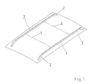
- Fig. 1 leaves the roof panel 1 of a vehicle with an arranged thereon Detect roof rack.
- the roof rack is made up of two roof rails, Consisting of support feet 2 and spars 3 and only dash-dotted lines indicated cross beams 4, which are attached to the spars 3, formed.
- the roof rails extend at least approximately parallel to each other and run in the direction of travel of the vehicle.
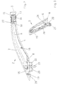
- Each support leg 2 consists essentially of a plastic body 5, one Stiffening body 6 and a cap body 7.
- the plastic body 5 has a support plate 8, which is on the Roof plate 1 supports.
- the support plate 8 closes in the axial direction an arcuately rising first wall 9, which is perpendicular to the Support plate 8 aligned end wall 10 ends.
- From the end wall 10 goes a pin 11 insertable into a spar end.
- the pin 11 has one first axially continuous and upwardly open groove 12 and one to this parallel second upwardly open groove 13.
- Further axially continuous Grooves 14 give the pin 11 radial suspension properties Direction to the wobble-free holder in the spar 3.
- From the free end of the support plate 8 to the end wall 10 runs one with the first wall 9 soft arcuate transition forming side wall 15 so that the Plastic body 5 has an L-shaped cross section.
- the plastic body 5 also has an undercut at the free end region of the pin 11 Nose 16, which is able to snap into a spar opening 17.
- One on the body 6 on the plastic body 5, while holes 19 in the support plate 8 are intended to fix the cap body 7.
- a cuboid extension 20 is formed on the underside of the support plate 8.
- A extends through the support plate 8 and the extension 20 Hole for passing a fastening screw 21.
- a metal bushing 22 is arranged, the flow behavior of the Plastic body 5 counteracts under load.
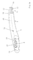
- the stiffening body 6 is an elongated one from a sheet metal blank formed part with a U-shaped cross section over almost the entire Length. Only at one end region 23 are the legs 24 spaced apart to each other, while the legs 24 otherwise via a web are interconnected. An opening 25 in the stiffening body 6 serves for passing the pin 18 on the plastic body 5 and a bore 26 to carry out the fastening screw 21.
- the stiffening body 6 is with the plastic body 5 by mere Hanging up connected.
- the end region 23 is supported in the groove 12 other end area on the platen 8 and the rest of the area on the first Wall 9 off.
- the pin 18 passes through the opening 25, provided for can be, the pin 18 for the purpose of making a clip connection a mushroom head, not shown. But it is also conceivable on To form pin 18 by thermal action on a rivet head.
- the cap body 7 is connected to the plastic body 5 around the stiffening body 6 cover and the support foot 2 to a massive appearance to lend.
- the cap body 7, preferably a plastic injection molding, is the Adapted shape of the plastic body 5 and has an approach at one end 27, which is to be inserted into the groove 13 on the pin 11. So that's the Cap body 7 fixed after mounting the support foot 2 on the spar 3, which is shown particularly clearly in FIG. 2.
- the cap body 7 has a clip element 28 for engagement in a hole 19 on the plastic body 5. If necessary, the arrangement to provide further clip connections.
Landscapes
- Engineering & Computer Science (AREA)
- Mechanical Engineering (AREA)
- Fittings On The Vehicle Exterior For Carrying Loads, And Devices For Holding Or Mounting Articles (AREA)
- Body Structure For Vehicles (AREA)
Claims (5)
- Galerie de toit pour véhicule avec un longeron (3) et des pieds d'appui (2) aux extrémités du longeron, qui peuvent être fixés à un toit de véhicule (1) et supportent le longeron (3) dans une position écartée du toit du véhicule (1), dans laquellecaractérisée en ce quechaque pied d'appui (2) se compose d'un corps de plastique moulé par injection (5), d'un corps de renforcement (6) et d'un corps de recouvrement (7) couvrant le corps de renforcement (6),le corps de plastique (5) présente une plaque d'appui plane (8) s'appuyant sur le toit du véhicule (1),la plaque d'appui (8) se prolonge en direction axiale en une première paroi (9) montante en forme d'arc, qui se termine par une face d'extrémité (10) orientée perpendiculairement à la plaque d'appui (8),un tenon (11) à insérer dans une extrémité de longeron sort de la face d'extrémité (10),une paroi latérale (15) formant une transition douce en forme d'arc avec la première paroi (9) va de l'extrémité libre de la plaque d'appui (8) jusqu'à la face d'extrémité (10), de telle façon que le corps de plastique (5) possède une section transversale en L depuis la plaque d'appui (8) jusqu'à la face d'extrémité (10),le corps de renforcement (6) présente, dans sa région d'extrémité du côté de la plaque d'appui, un alésage (26) se prolongeant à travers la plaque d'appui (8) pour le passage d'une vis de fixation (21) destinée à caler le pied d'appui (2) sur le toit du véhicule (1), et dans laquellele corps de recouvrement (7) possède une configuration adaptée à la forme du corps de plastique (5) et recouvre celui-ci de l'extrémité libre de la plaque d'appui (8) jusque et y compris la face d'extrémité (10) et présente en outre des organes de clippage (28) pour la fixation au corps de plastique (5) et/ou au corps de renforcement (6),le tenon (11) présente une première rainure axiale (12) ouverte vers le haut, qui traverse aussi la face d'extrémité (10) et une deuxième rainure axiale (13) ouverte vers le haut et orientée parallèlement à celle-ci,le corps de renforcement (6) est un corps métallique et se compose d'un coupon de tôle déformé, qui s'appuie par une première région d'extrémité sur la plaque d'appui (8), par l'autre région d'extrémité (23) dans la première rainure axiale (12) et pour le reste sur la première paroi (9),le corps de renforcement (6) présente, sur sa dimension axiale, une section transversale en U avec deux branches (24) reliées l'une à l'autre par une âme, à l'exception de la région d'extrémité (23) engagée dans la première rainure axiale (12), pour laquelle les branches (24) sont appliquées l'une contre l'autre sans écartement, et en ce quele corps de recouvrement (7) présente une languette en saillie (27), qui s'engage dans la région de la face d'extrémité (10) dans la deuxième rainure axiale (13) du tenon (11) à insérer dans une extrémité de longeron.
- Galerie de toit suivant la revendication 1, caractérisée en ce que le corps de plastique (5) présente des tenons façonnés (18) avec des têtes en forme de champignons, qui traversent des ouvertures (25) prévues dans le corps de renforcement (6).
- Galerie de toit suivant la revendication 1 ou 2, caractérisée en ce que la plaque d'appui (8) présente, sur sa face inférieure, une saillie parallélépipédique (20) s'engageant dans un creux du toit, comme une rainure, dans laquelle se trouve l'alésage prolongé (26), qui présente une douille métallique (22) insérée intérieurement.
- Galerie de toit suivant au moins l'une des revendications 1 à 3, caractérisée en ce que plusieurs rainures axiales supplémentaires (14) s'étendent sur le tenon (11).
- Galerie de toit suivant au moins l'une des revendications 1 à 4, caractérisée en ce qu'un ergot (16) verrouillable dans une ouverture (17) du longeron est façonné sur le tenon (11).
Applications Claiming Priority (2)
| Application Number | Priority Date | Filing Date | Title |
|---|---|---|---|
| DE19617305A DE19617305A1 (de) | 1996-04-30 | 1996-04-30 | Dachreling für Fahrzeuge |
| DE19617305 | 1996-04-30 |
Publications (3)
| Publication Number | Publication Date |
|---|---|
| EP0805068A2 EP0805068A2 (fr) | 1997-11-05 |
| EP0805068A3 EP0805068A3 (fr) | 1998-09-16 |
| EP0805068B1 true EP0805068B1 (fr) | 2001-08-22 |
Family
ID=7792906
Family Applications (1)
| Application Number | Title | Priority Date | Filing Date |
|---|---|---|---|
| EP97100175A Expired - Lifetime EP0805068B1 (fr) | 1996-04-30 | 1997-01-08 | Rails de toit pour véhicules |
Country Status (2)
| Country | Link |
|---|---|
| EP (1) | EP0805068B1 (fr) |
| DE (2) | DE19617305A1 (fr) |
Families Citing this family (7)
| Publication number | Priority date | Publication date | Assignee | Title |
|---|---|---|---|---|
| GB0124675D0 (en) * | 2001-10-13 | 2001-12-05 | Thule Automotive Ltd | Roof rail |
| US20060086767A1 (en) * | 2004-09-21 | 2006-04-27 | Sportrack Llc | Stanchion assembly |
| DE102006030760A1 (de) * | 2006-06-26 | 2007-12-27 | Decoma (Germany) Gmbh | Tragteil |
| WO2008025133A1 (fr) | 2006-08-29 | 2008-03-06 | Magna International Inc. | Éléments structuraux moules par injection a l'aide d'eau |
| DE102007005653A1 (de) | 2007-01-31 | 2008-08-07 | Jac Products Deutschland Gmbh | Dachreling für Fahrzeuge |
| DE102008004967A1 (de) * | 2008-01-11 | 2009-08-06 | Hans und Ottmar Binder GmbH Oberflächenveredelung | Tiefziehkappe für Dachreling |
| DE102011051613A1 (de) * | 2011-07-06 | 2013-01-10 | Dura Automotive Body & Glass Systems Gmbh | Befestigungssystem für einen Kraftfahrzeugdachträger |
Family Cites Families (5)
| Publication number | Priority date | Publication date | Assignee | Title |
|---|---|---|---|---|
| DE3230346A1 (de) | 1982-08-14 | 1984-02-16 | Keiper Automobiltechnik Gmbh | Tragkoerper zum abstuetzen einer dachreling am zugehoerigen fahrzeugdach |
| DE3539449A1 (de) | 1985-11-07 | 1987-05-21 | Erbsloeh Julius & August | Verbindung von leichtmetallprofilen mit anschlusselementen |
| GB2232943B (en) * | 1989-06-07 | 1993-09-01 | Huron St Clair Inc | Support stanchion for luggage carrier |
| DE4315688A1 (de) * | 1993-05-11 | 1994-11-17 | Ymos Ag Ind Produkte | Dachlastträger mit mehrteiligen Stützfüßen |
| DE4321537A1 (de) * | 1993-06-29 | 1995-01-12 | Happich Gmbh Gebr | Dachreling für Fahrzeuge |
-
1996
- 1996-04-30 DE DE19617305A patent/DE19617305A1/de not_active Withdrawn
-
1997
- 1997-01-08 EP EP97100175A patent/EP0805068B1/fr not_active Expired - Lifetime
- 1997-01-08 DE DE59704348T patent/DE59704348D1/de not_active Expired - Fee Related
Also Published As
| Publication number | Publication date |
|---|---|
| EP0805068A2 (fr) | 1997-11-05 |
| EP0805068A3 (fr) | 1998-09-16 |
| DE59704348D1 (de) | 2001-09-27 |
| DE19617305A1 (de) | 1997-11-06 |
Similar Documents
| Publication | Publication Date | Title |
|---|---|---|
| DE602004001734T2 (de) | Ein Befestigungselement zur Verbindung von an einem Trägerteil | |
| DE19716047C2 (de) | Befestigungsvorrichtung für Dachlastträger | |
| DE69909390T2 (de) | Klammeranordnung | |
| EP2804786B1 (fr) | Rail de toit pour un véhicule | |
| EP1084655A1 (fr) | Système de fixation | |
| EP0903286B1 (fr) | Appareil pour monter, positionner et fixer une pièce de carosserie par liason de forme | |
| EP0654380B1 (fr) | Rails de toit pour véhicules | |
| DE3501048C2 (fr) | ||
| EP0689965B1 (fr) | Rails de toit pour véhicules | |
| EP0805068B1 (fr) | Rails de toit pour véhicules | |
| DE19625632A1 (de) | Gepäckträger für Fahrzeuge | |
| EP1157636A1 (fr) | Système de fixation | |
| DE2856493A1 (de) | Zierleistenklemme | |
| EP1544029B1 (fr) | Repose-pied pouvant être monté au plancher d'un véhicule | |
| EP1862356B1 (fr) | Clip de fixation | |
| EP0536471B1 (fr) | Plaque de moulage pour charnières de meubles | |
| DE60009465T2 (de) | Vorrichtung zur befestigung einer an einer stossstange integrierten kotflügelverbreiterung | |
| DE60000506T2 (de) | Stossfänger für ein kraftfahrzeug | |
| EP1213186A2 (fr) | Dispositif de fixation de deux pièces entre-elles | |
| DE4418528C1 (de) | Dachreling für Fahrzeuge | |
| DE4333479A1 (de) | Befestigung einer Aufhängevorrichtung, insbesondere eines Kleiderhakens in einem Fahrzeug | |
| EP2097298B1 (fr) | Balai d'essuie-glace | |
| EP0806321A2 (fr) | Rails de toit pour véhicules | |
| EP0531720A1 (fr) | Système de fixation pour des éléments de montage visibles pour véhicules, en particulier véhicules automobiles | |
| EP1036707A2 (fr) | Rail de toit pour véhicules |
Legal Events
| Date | Code | Title | Description |
|---|---|---|---|
| PUAI | Public reference made under article 153(3) epc to a published international application that has entered the european phase |
Free format text: ORIGINAL CODE: 0009012 |
|
| 17P | Request for examination filed |
Effective date: 19970123 |
|
| AK | Designated contracting states |
Kind code of ref document: A2 Designated state(s): DE FR GB SE |
|
| PUAL | Search report despatched |
Free format text: ORIGINAL CODE: 0009013 |
|
| AK | Designated contracting states |
Kind code of ref document: A3 Designated state(s): DE FR GB SE |
|
| RAP1 | Party data changed (applicant data changed or rights of an application transferred) |
Owner name: JAC PRODUCTS DEUTSCHLAND GMBH |
|
| 17Q | First examination report despatched |
Effective date: 20000204 |
|
| GRAG | Despatch of communication of intention to grant |
Free format text: ORIGINAL CODE: EPIDOS AGRA |
|
| GRAG | Despatch of communication of intention to grant |
Free format text: ORIGINAL CODE: EPIDOS AGRA |
|
| GRAH | Despatch of communication of intention to grant a patent |
Free format text: ORIGINAL CODE: EPIDOS IGRA |
|
| GRAH | Despatch of communication of intention to grant a patent |
Free format text: ORIGINAL CODE: EPIDOS IGRA |
|
| GRAA | (expected) grant |
Free format text: ORIGINAL CODE: 0009210 |
|
| AK | Designated contracting states |
Kind code of ref document: B1 Designated state(s): DE FR GB SE |
|
| REF | Corresponds to: |
Ref document number: 59704348 Country of ref document: DE Date of ref document: 20010927 |
|
| GBT | Gb: translation of ep patent filed (gb section 77(6)(a)/1977) |
Effective date: 20011117 |
|
| REG | Reference to a national code |
Ref country code: GB Ref legal event code: IF02 |
|
| ET | Fr: translation filed | ||
| PG25 | Lapsed in a contracting state [announced via postgrant information from national office to epo] |
Ref country code: GB Free format text: LAPSE BECAUSE OF NON-PAYMENT OF DUE FEES Effective date: 20020108 |
|
| PG25 | Lapsed in a contracting state [announced via postgrant information from national office to epo] |
Ref country code: SE Free format text: LAPSE BECAUSE OF NON-PAYMENT OF DUE FEES Effective date: 20020109 |
|
| PLBE | No opposition filed within time limit |
Free format text: ORIGINAL CODE: 0009261 |
|
| STAA | Information on the status of an ep patent application or granted ep patent |
Free format text: STATUS: NO OPPOSITION FILED WITHIN TIME LIMIT |
|
| PG25 | Lapsed in a contracting state [announced via postgrant information from national office to epo] |
Ref country code: DE Free format text: LAPSE BECAUSE OF NON-PAYMENT OF DUE FEES Effective date: 20020801 |
|
| 26N | No opposition filed | ||
| EUG | Se: european patent has lapsed |
Ref document number: 97100175.5 |
|
| GBPC | Gb: european patent ceased through non-payment of renewal fee |
Effective date: 20020108 |
|
| PG25 | Lapsed in a contracting state [announced via postgrant information from national office to epo] |
Ref country code: FR Free format text: LAPSE BECAUSE OF NON-PAYMENT OF DUE FEES Effective date: 20020930 |
|
| REG | Reference to a national code |
Ref country code: FR Ref legal event code: ST |