EP0805317A1 - Réfrigérateur cryogènique pour échantillon - Google Patents
Réfrigérateur cryogènique pour échantillon Download PDFInfo
- Publication number
- EP0805317A1 EP0805317A1 EP97303045A EP97303045A EP0805317A1 EP 0805317 A1 EP0805317 A1 EP 0805317A1 EP 97303045 A EP97303045 A EP 97303045A EP 97303045 A EP97303045 A EP 97303045A EP 0805317 A1 EP0805317 A1 EP 0805317A1
- Authority
- EP
- European Patent Office
- Prior art keywords
- cooling
- cooling means
- refrigerator according
- liquid helium
- tube
- Prior art date
- Legal status (The legal status is an assumption and is not a legal conclusion. Google has not performed a legal analysis and makes no representation as to the accuracy of the status listed.)
- Granted
Links
- 239000007788 liquid Substances 0.000 claims abstract description 51
- 238000001816 cooling Methods 0.000 claims abstract description 49
- 239000001307 helium Substances 0.000 claims abstract description 43
- 229910052734 helium Inorganic materials 0.000 claims abstract description 43
- SWQJXJOGLNCZEY-UHFFFAOYSA-N helium atom Chemical compound [He] SWQJXJOGLNCZEY-UHFFFAOYSA-N 0.000 claims abstract description 43
- 239000002826 coolant Substances 0.000 claims abstract description 28
- 238000009833 condensation Methods 0.000 claims abstract description 18
- 230000005494 condensation Effects 0.000 claims abstract description 18
- 238000001179 sorption measurement Methods 0.000 claims abstract description 16
- 239000003507 refrigerant Substances 0.000 claims abstract description 14
- 238000010438 heat treatment Methods 0.000 claims description 4
- 238000010790 dilution Methods 0.000 claims description 3
- 239000012895 dilution Substances 0.000 claims description 3
- 239000000203 mixture Substances 0.000 claims description 2
- 238000005086 pumping Methods 0.000 description 15
- 239000007789 gas Substances 0.000 description 9
- 230000008929 regeneration Effects 0.000 description 7
- 238000011069 regeneration method Methods 0.000 description 7
- 238000004574 scanning tunneling microscopy Methods 0.000 description 7
- 238000010586 diagram Methods 0.000 description 6
- RYGMFSIKBFXOCR-UHFFFAOYSA-N Copper Chemical compound [Cu] RYGMFSIKBFXOCR-UHFFFAOYSA-N 0.000 description 5
- 239000000463 material Substances 0.000 description 5
- 229910052802 copper Inorganic materials 0.000 description 4
- 239000010949 copper Substances 0.000 description 4
- 101100493711 Caenorhabditis elegans bath-41 gene Proteins 0.000 description 2
- 239000003463 adsorbent Substances 0.000 description 2
- 230000003247 decreasing effect Effects 0.000 description 2
- 238000002474 experimental method Methods 0.000 description 2
- 230000002706 hydrostatic effect Effects 0.000 description 2
- 238000011835 investigation Methods 0.000 description 2
- 230000005355 Hall effect Effects 0.000 description 1
- 238000009835 boiling Methods 0.000 description 1
- 239000003610 charcoal Substances 0.000 description 1
- 230000001419 dependent effect Effects 0.000 description 1
- 238000001704 evaporation Methods 0.000 description 1
- 230000008020 evaporation Effects 0.000 description 1
- 238000005259 measurement Methods 0.000 description 1
- 238000001956 neutron scattering Methods 0.000 description 1
- 230000003287 optical effect Effects 0.000 description 1
- 239000002245 particle Substances 0.000 description 1
- 230000005855 radiation Effects 0.000 description 1
- 238000005057 refrigeration Methods 0.000 description 1
- 229920006395 saturated elastomer Polymers 0.000 description 1
- 239000004065 semiconductor Substances 0.000 description 1
Images



Classifications
-
- F—MECHANICAL ENGINEERING; LIGHTING; HEATING; WEAPONS; BLASTING
- F25—REFRIGERATION OR COOLING; COMBINED HEATING AND REFRIGERATION SYSTEMS; HEAT PUMP SYSTEMS; MANUFACTURE OR STORAGE OF ICE; LIQUEFACTION SOLIDIFICATION OF GASES
- F25J—LIQUEFACTION, SOLIDIFICATION OR SEPARATION OF GASES OR GASEOUS OR LIQUEFIED GASEOUS MIXTURES BY PRESSURE AND COLD TREATMENT OR BY BRINGING THEM INTO THE SUPERCRITICAL STATE
- F25J1/00—Processes or apparatus for liquefying or solidifying gases or gaseous mixtures
- F25J1/02—Processes or apparatus for liquefying or solidifying gases or gaseous mixtures requiring the use of refrigeration, e.g. of helium or hydrogen ; Details and kind of the refrigeration system used; Integration with other units or processes; Controlling aspects of the process
- F25J1/0243—Start-up or control of the process; Details of the apparatus used; Details of the refrigerant compression system used
- F25J1/0257—Construction and layout of liquefaction equipments, e.g. valves, machines
- F25J1/0275—Construction and layout of liquefaction equipments, e.g. valves, machines adapted for special use of the liquefaction unit, e.g. portable or transportable devices
- F25J1/0276—Laboratory or other miniature devices
-
- F—MECHANICAL ENGINEERING; LIGHTING; HEATING; WEAPONS; BLASTING
- F25—REFRIGERATION OR COOLING; COMBINED HEATING AND REFRIGERATION SYSTEMS; HEAT PUMP SYSTEMS; MANUFACTURE OR STORAGE OF ICE; LIQUEFACTION SOLIDIFICATION OF GASES
- F25B—REFRIGERATION MACHINES, PLANTS OR SYSTEMS; COMBINED HEATING AND REFRIGERATION SYSTEMS; HEAT PUMP SYSTEMS
- F25B9/00—Compression machines, plants or systems, in which the refrigerant is air or other gas of low boiling point
- F25B9/10—Compression machines, plants or systems, in which the refrigerant is air or other gas of low boiling point with several cooling stages
-
- F—MECHANICAL ENGINEERING; LIGHTING; HEATING; WEAPONS; BLASTING
- F25—REFRIGERATION OR COOLING; COMBINED HEATING AND REFRIGERATION SYSTEMS; HEAT PUMP SYSTEMS; MANUFACTURE OR STORAGE OF ICE; LIQUEFACTION SOLIDIFICATION OF GASES
- F25B—REFRIGERATION MACHINES, PLANTS OR SYSTEMS; COMBINED HEATING AND REFRIGERATION SYSTEMS; HEAT PUMP SYSTEMS
- F25B9/00—Compression machines, plants or systems, in which the refrigerant is air or other gas of low boiling point
- F25B9/12—Compression machines, plants or systems, in which the refrigerant is air or other gas of low boiling point using 3He-4He dilution
-
- F—MECHANICAL ENGINEERING; LIGHTING; HEATING; WEAPONS; BLASTING
- F25—REFRIGERATION OR COOLING; COMBINED HEATING AND REFRIGERATION SYSTEMS; HEAT PUMP SYSTEMS; MANUFACTURE OR STORAGE OF ICE; LIQUEFACTION SOLIDIFICATION OF GASES
- F25J—LIQUEFACTION, SOLIDIFICATION OR SEPARATION OF GASES OR GASEOUS OR LIQUEFIED GASEOUS MIXTURES BY PRESSURE AND COLD TREATMENT OR BY BRINGING THEM INTO THE SUPERCRITICAL STATE
- F25J2290/00—Other details not covered by groups F25J2200/00 - F25J2280/00
- F25J2290/42—Modularity, pre-fabrication of modules, assembling and erection, horizontal layout, i.e. plot plan, and vertical arrangement of parts of the cryogenic unit, e.g. of the cold box
Definitions
- the present invention relates to improvements in cryogenic refrigeration.
- a number of known cryogenic systems are available for obtaining "ultra-low" temperatures - typically in the range of 1mK - 1.5K.
- a dilution refrigerator which uses the two isotopes of helium ( 3 He and 4 He) to produce temperatures of 5mK or below.
- An alternative system is known as a 3 He refrigerator which uses the boiling of 3 He to provide cooling for an experiment. Temperatures as low as 0.3K may be achieved by this type of system.
- Some 3 He refrigerators are single shot sorption pumped systems, whilst others circulate the gas on a continuous basis, using a room temperature pumping system.
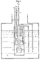
- FIG. 1 An example of a conventional 3 He refrigerator is illustrated in Figure 1. A number of elements of the system have been omitted in the interests of clarity.
- the system comprises an evacuated insert 1 which is immersed in a 4 He bath 2 at approximately 4.2K.
- the insert 1 contains inter alia, a 3 He pot 3 containing liquid 3 He 4 in use and, a 3 He filling/pumping tube 5 which is filled via a 3 He filling tube 6 connected to a 3 He storage dump (not shown) via a suitable valve.
- the liquid helium bath 2 is mounted in a suitable cryostat.
- a sample 7 is mounted in vacuum on the base of the 3 He pot 3.
- a 4 He “1K pot” 8 is mounted to the 3 He tube 5 such that it conducts heat away from the walls of the tube 5 in the positions indicated at 9.
- the 1K pot 8 is filled with liquid 4 He 10 by an inlet tube 11 which is immersed in the liquid helium bath 2 and includes a needle valve 12 (or any other fixed impedance).
- the vapour of liquid 4 He 10 in the 1K pot is pumped to a low pressure by a rotary pump attached to exhaust tube 13 to reduce its temperature.
- the 1K pot 8 is filled continuously through the variable flow needle valve 12, set for the required flow rate. By pumping off the 4 He vapour above the liquid 4 He 10, the temperature of the liquid 4 He 10 is reduced to 1-2K.
- the insert 1 also contains a sorption pump (or sorb) 14.
- the sorption pump is a vacuum pump which works by adsorbing gas.
- the adsorbent material is usually charcoal (or other material with a very large surface area).
- the sorb 14 is warmed, it releases gas, and when it is cooled again it pumps (i.e. adsorbs) the gas to a pressure dependent upon the temperature. A very high (and clean) vacuum can be achieved by this type of pump.
- the sorb 14 is cooled by a heat exchanger 15 which is fed with 4 He from the helium bath 2 via inlet tube 16 and needle valve 17. The 4 He flows through the heat exchanger 15 controlled by valve 17 and exits via exhaust tube 18, which may also be fitted with a suitable pump.
- the sorb 14 may also be fitted with a heater (not shown).
- FIGs 2A and 2B Typical operation of the sorption pump 3 He refrigerator system of Figure 1 is illustrated in Figures 2A and 2B, which illustrate the insert 1 only.
- the 1K pot 8 is pumped and the needle valve 12 is opened slightly to allow liquid helium to flow into the pot 8, cooling it to below 1.5K.
- the sorb 14 is warmed above 40K by the heater so that it will not adsorb 3 He gas (or will release adsorbed gas).
- the 3 He gas is free to condense on the 1K pot assembly 8 and runs down to cool the 3 He pot 3 and sample 7.
- the flow of 3 He in this situation is illustrated in Figure 2A. After a period of time, most of the 3 He gas should have condensed to give liquid 3 He 10 in the 3 He pot. At this stage the 3 He pot 3 is nearly full of liquid 3 He at approximately 1.5K.
- the sorb 14 is now cooled, and it begins to reduce the vapour pressure of the liquid 3 He 10 so that the sample temperature drops.
- the flow of 3 He in this situation is illustrated in Figure 2B.
- a base temperature below 0.3K can typically be achieved in this type of cryostat, with no experimental heat load.
- the 1K pot valve 12 is then set to fill continuously.
- a refrigerator for cooling a sample comprising a container for holding liquid helium refrigerant to cool the sample, first cooling means for cooling a condensation region with liquid helium coolant whereby helium refrigerant condenses on the condensation region and collects in the container, a sorption pump adapted to pump gaseous helium refrigerant from the container, and second cooling means for cooling the sorption pump with the liquid helium coolant, characterised in that the first and second cooling means are connected in series with a source of the liquid helium coolant.
- the refrigerator according to the present invention provides a number of advantages over conventional refrigerators. Firstly, by providing both cooling means on the same helium coolant line, only a single needle valve or fixed impedance (for controlling the flow of helium coolant) is required for both cooling means. Secondly, since both cooling means are provided with helium coolant (typically liquid 4 He) at substantially the same temperature, the sorb can be cooled to a lower temperature than in a conventional device. Since the pumping efficiency of a sorb is related to its temperature, this increases the pumping power of the sorb for a given volume of adsorbent material. As a result the sorb volume can be reduced.
- helium coolant typically liquid 4 He
- the temperature of the helium coolant can be reduced (in a similar manner to the "1K pot" previously described) to 1-2K.
- the sorb can be cooled well below the 4.2K which can be achieved in a conventionally cooled device.
- the first and second cooling means are connected by a tube such as a capillary tube.
- a tube such as a capillary tube.
- the capillary tube has an internal diameter of 1-2mm.
- the helium coolant may be forced through the cooling circuit by providing a pressurised source of helium coolant.
- one of the first and second cooling means is connected by a first tube (e.g. capillary tube) to the source of liquid helium coolant and the other of the first and second cooling means is connected by a second tube (e.g. capillary tube) to a pump.
- the pump removes gaseous helium coolant above the liquid level and thus lowers the temperature of the helium coolant.
- the first and second cooling means are part of a cooling circuit which comprises one or more lengths of coiled tube (e.g. coiled capillary tube) which is typically adapted to extend and compress (i.e. decrease and increase respectively the number of coil turns/m) to enable movement of the sample.
- coiled tube e.g. coiled capillary tube
- compress i.e. decrease and increase respectively the number of coil turns/m
- the first and second tubes are both coiled in this way.
- the refrigerator further comprises a heater for heating the sorption pump to regenerate the sorption pump.
- the capillary tube may be coiled to increase the length of tube between the first and second cooling means - thus decreasing the temperature gradient along the tube between the first and second cooling means. This is of particular importance during regeneration of the sorption pump.
- the refrigerator further comprises bypass means for bypassing liquid helium coolant around the second cooling means.
- the bypass means may be a coiled capillary tube. This provides a low hydraulic impedance bypass for liquid helium coolant during regeneration of the sorption pump.
- the refrigerator may comprise a dilution refrigerator which uses a 3 He/ 4 He mixture as refrigerant or a 3 He refrigerator which uses 3 He as refrigerant.
- the present invention also extends to apparatus for investigating a sample, the apparatus comprising a refrigerator according to the invention for cooling the sample.
- the apparatus may comprise a particle, X-ray or radiation detector, semi-conductor physics investigation apparatus, neutron scattering experiment, apparatus for magnetic and optical measurement, apparatus for investigating fractional quantised and quantised Hall effect, apparatus for mesoscopic studies, apparatus for investigation of low dimensional systems or apparatus for Scanning Tunnelling Microscopy (STM).
- STM Scanning Tunnelling Microscopy
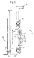
- FIG 3 is a schematic diagram of a first embodiment of a 3 He refrigerator according to the present invention.
- Main bath 20 contains liquid 4 He at approximately 4.2K which surrounds the helium insert (generally indicated at 21) and cools it to approximately 4.2K, as well as providing 4 He coolant.
- the 4 He coolant flows through inlet tube 22 and needle valve 23 to capillary tube 24.
- the capillary tube 24 has a first 4m long coiled section 25, a second 4m long coiled section 26 and an intermediate portion 27.
- the capillary tube 24 is connected at its far end to a rotary pump 28, which pumps off 4 He gas to lower the temperature of the 4 He in the capillary to 1-2K.
- the 3 He pot 29 contains liquid 3 He in use to cool a sample (not shown).
- the 3 He pot 29 is enclosed in an evacuated 1K shield 30.
- the 3 He pot 29 is connected to a sorb 31 via a filling/pumping tube 32.
- a condensation region 33 of the pumping tube 32 is cooled by suitable heat exchange with the intermediate section 27 of the capillary tube (as indicated schematically at 34).
- the sorb 31 is cooled by suitable heat exchange (as indicated schematically at 35) with the intermediate portion 27 of the capillary tube.
- the apparatus between coiled sections 25,26 can move as a unit as indicated at 36.
- Figure 4A illustrates an evacuated insert 40 immersed in a 4 He refrigerant bath 41.
- Sample chamber 42 is mounted below 3 He pot 43.
- 3 He filling/pumping tube 44 is filled with 3 He via inlet tube 145 (connected to a source of 3 He not shown).
- Sorb 45 and condensation region 46 are both cooled by capillary tube 47 which receives 4 He from the bath 41 via inlet tube 48 and needle valve 72.
- Part of the insert 40 between points A-A is illustrated in cross-section in Figure 4B.
- the lower half of the capillary tube 47 is coiled round the sample chamber 42 and 3 He pot 43 as indicated at 50.
- the last turn 51 of the spiral 50 is connected via a standard connector 52 and capillary tube 53 to a heat exchanger.
- the heat exchanger comprises an annular chamber 54 which is in heat conducting contact with flange 83 of copper tube 55. Copper tube 55 provides a 3 He condensation region 46 on its inner surface.
- the heat exchanger chamber 54 is connected to an outlet capillary tube 56 which is connected in turn to a T-junction connector 57.
- the T-junction connector 57 is connected in turn to a coiled bypass capillary tube 58 and a coiled capillary tube 59.
- the capillary tube 59 is connected to a second heat exchanger which cools the sorb 45.
- the second heat exchanger is of a similar design to the first heat exchanger (54,55,83) and comprises an annular chamber 60 in heat conducting contact with a copper ring 84 which in turn is in contact with the lower edge 85 of the sorb material.
- the heat exchanger chamber 60 is connected in turn to an outlet capillary tube 61 which is connected with the bypass capillary 58 by a second T-junction connector 62.
- the second T-junction connector 62 is connected in turn to a capillary tube 63 which is coiled at 64 around the sorb 45 and exits at 65.
- the capillary tube 65 is connected to a rotary pump 28 at the top of the insert 40 in the direction indicated at 66.
- All lengths of capillary tube in Figures 4A and 4B have an outer diameter of 2mm and an inner diameter of 1.5mm.
- the 3 He pot 43 is in its raised position. This can be seen by the fact that the lower coil 50 has widely separated turns (i.e. it is in its extended state) and the upper coil 64 has closely spaced turns (i.e. it is in its compressed state).
- the sample holder 42 In its raised position the sample holder 42 is positioned in a region of high magnetic field in the bore of a magnet 71. Experimental studies such as Scanning Tunnelling Microscopy (STM) can then be carried out on the sample.
- STM Scanning Tunnelling Microscopy
- Figures 5A, 5B and 5C are schematic diagrams which illustrate the 4 He liquid level in the cooling capillary tube and the direction of flow of the 4 He in the cooling tube during cooling of the sorb in the pumping off regime ( Figure 5A) and sorb regeneration ( Figures 5B and 5C).
- FIG 5A schematically illustrates the cooling line during pumping mode. It can be seen that during cooling the liquid 4 He level 80 lies above the sorb 45 and above the 3 He condensation point heat exchanger 54. The flow of 4 He is illustrated by arrows 81. It can be seen that the predominant flow of liquid 4 He is through the sorb heat exchanger and not through the bypass tube 58. However, during sorb regeneration the sorb 45 heats up the heat exchanger 60 and causes the liquid helium in the region of the capillary tube indicated at 82 to boil off. Without the bypass tube 58, the liquid 4 He level 80 would drop to a point between the sorb 45 and the heat exchanger chamber 54, and may even drop below the heat exchanger 54.
- heating of the capillary tube will increase the hydraulic impedance to flow of 4 He.
- a bypass tube 58 a low impedance path is provided round the heated sorb 45 (ie. in parallel with the portion 82 of the capillary tube) since the bypass tube 58 is not heated, resulting in a liquid 4 He flow as indicated in Figure 5B.
- a vapour lock develops in the portion 82 of the capillary tube. Therefore the 1K pot condensation region 46 is kept cold as the 4 He level does not drop below the condensation region 46.
- Figure 5C illustrates an alternative flow regime in which the liquid level 80' lies below the T-connector 62.
- no vapour lock is present in the region 82 and 4 He evaporates directly around the coiled capillary 64.
- Coiling of the capillary tube 59 increases the length between the heat exchanger 54 and the sorb heat exchanger 60, thus decreasing the temperature gradient, in particular during sorb regeneration ( Figure 5B). This helps to ensure that the liquid 4 He level does not drop below the first heat exchanger chamber 54, which needs to maintain the condensation condition for the 3 He in condensation region 46.
- the liquid 4 He level 80 should be at the top end of the capillary tube 65.
- the total height of liquid 4 He depends upon the heat load from the top flange of the cryostat. In a particular embodiment of the apparatus, the total length of the capillary tube is approximately 8 metres and the height of liquid 4 He is approximately 1 metre.
- the height will produce a hydrostatic pressure difference between the top of the spiral 64 and the bottom of the spiral 50.
- the hydrostatic pressure is about 8 torr per metre of height which can cause an increase of the temperature at the bottom of up to 1.8K (assuming that the pressure at the top is 4 torr and the temperature is 1.5K). However, since the 4 He will be superfluid this will tend to decrease the temperature gradient.
- the final temperature is typically between 1.5 and 1.8K.
- Figure 6 is a schematic diagram of an alternative example of a 3 He refrigerator according to the present invention.
- 3 He pot 90 is connected to filling/pumping tube 91.
- Pick up tube 92 is connected to a 4.2 K 4 He reservoir via a needle valve or fixed impedance (not shown).
- the pick up tube 92 supplies 4 He to a 1K platform 99 comprising a capillary tube coiled twice around a copper heat exchanger 93 which provides a 3 He condensation region on its inner bore 94.
- the 4 He cooling circuit continues with a length of capillary 100 which is then coiled four times around the pumping tube 91 at 95.
- the cooling circuit is then extended into the sorb 96.
- the sorb heat exchanger comprises a length of copper tube 97 which has a greater diameter than the capillary tube and passes through the sorb material.
- the sorb heat exchanger 97 is connected to a rotary pump at 98.
- the larger diameter and shorter length of the sorb heat exchanger 97 in the embodiment of Figure 6 ensures that in regeneration mode, evaporation of 4 He in the region of the sorb will not significantly affect the temperature of the 1-2K platform 99.
Landscapes
- Engineering & Computer Science (AREA)
- Physics & Mathematics (AREA)
- Mechanical Engineering (AREA)
- Thermal Sciences (AREA)
- General Engineering & Computer Science (AREA)
- Clinical Laboratory Science (AREA)
- Health & Medical Sciences (AREA)
- Sampling And Sample Adjustment (AREA)
- Superconductors And Manufacturing Methods Therefor (AREA)
- Devices That Are Associated With Refrigeration Equipment (AREA)
- Vaporization, Distillation, Condensation, Sublimation, And Cold Traps (AREA)
- Carbon And Carbon Compounds (AREA)
- Inorganic Insulating Materials (AREA)
- Filling Or Discharging Of Gas Storage Vessels (AREA)
- Separation By Low-Temperature Treatments (AREA)
Applications Claiming Priority (2)
| Application Number | Priority Date | Filing Date | Title |
|---|---|---|---|
| GBGB9609311.7A GB9609311D0 (en) | 1996-05-03 | 1996-05-03 | Improvements in cryogenics |
| GB9609311 | 1996-05-03 |
Publications (2)
| Publication Number | Publication Date |
|---|---|
| EP0805317A1 true EP0805317A1 (fr) | 1997-11-05 |
| EP0805317B1 EP0805317B1 (fr) | 2002-04-17 |
Family
ID=10793164
Family Applications (1)
| Application Number | Title | Priority Date | Filing Date |
|---|---|---|---|
| EP97303045A Expired - Lifetime EP0805317B1 (fr) | 1996-05-03 | 1997-05-02 | Réfrigérateur cryogènique pour échantillon |
Country Status (9)
| Country | Link |
|---|---|
| US (1) | US5829270A (fr) |
| EP (1) | EP0805317B1 (fr) |
| JP (1) | JPH1047803A (fr) |
| AT (1) | ATE216482T1 (fr) |
| DE (1) | DE69711977T2 (fr) |
| DK (1) | DK0805317T3 (fr) |
| ES (1) | ES2179275T3 (fr) |
| GB (1) | GB9609311D0 (fr) |
| PT (1) | PT805317E (fr) |
Cited By (3)
| Publication number | Priority date | Publication date | Assignee | Title |
|---|---|---|---|---|
| WO2006051251A1 (fr) * | 2004-11-09 | 2006-05-18 | Oxford Instruments Superconductivity Limited | Ensemble de cryostat |
| EP1785680A1 (fr) * | 2005-11-14 | 2007-05-16 | Oxford Instruments Superconductivity Limited | Appareil de refroidissement |
| WO2017055865A3 (fr) * | 2015-10-01 | 2017-05-04 | Iceoxford Limited | Appareil cryogénique |
Families Citing this family (5)
| Publication number | Priority date | Publication date | Assignee | Title |
|---|---|---|---|---|
| KR100454702B1 (ko) * | 2002-06-26 | 2004-11-03 | 주식회사 덕성 | 지엠냉각기를 구비한 극저온용기 및 극저온용기의 제어방법 |
| DE102006012508B3 (de) * | 2006-03-18 | 2007-10-18 | Bruker Biospin Gmbh | Kryostat mit einem Magnetspulensystem, das eine LTS- und eine gekapselte HTS-Sektion umfasst |
| GB2447040B (en) * | 2007-03-01 | 2009-07-15 | Oxford Instr Superconductivity | A method of operating an adsorption refrigeration system |
| US10724780B2 (en) * | 2018-01-29 | 2020-07-28 | Advanced Research Systems, Inc. | Cryocooling system and method |
| GB2616318B (en) | 2022-05-16 | 2024-05-15 | Oxford Instruments Nanotechnology Tools Ltd | Cryogenic cooling system |
Citations (5)
| Publication number | Priority date | Publication date | Assignee | Title |
|---|---|---|---|---|
| US2982106A (en) * | 1959-07-30 | 1961-05-02 | Ambler Ernest | Low temperature refrigeration apparatus and process |
| DE2744346A1 (de) * | 1977-10-01 | 1979-04-05 | Gerd Binnig | Direkt ladbarer mischkryostat mit proben-schnellwechsel |
| GB2166535A (en) * | 1984-09-26 | 1986-05-08 | Kernforschungsz Karlsruhe | Cryostat for operation of a <3>He <4>He mixing unit |
| SU1252620A1 (ru) * | 1984-12-17 | 1986-08-23 | Всесоюзный научно-исследовательский институт гелиевой техники | Установка дл производства холода сверхнизких температур |
| US5339649A (en) * | 1991-12-09 | 1994-08-23 | Kabushikikaisha Equos Research | Cryogenic refrigerator |
Family Cites Families (3)
| Publication number | Priority date | Publication date | Assignee | Title |
|---|---|---|---|---|
| FR2574914B1 (fr) * | 1984-12-17 | 1987-03-06 | Centre Nat Rech Scient | Cryostat a dilution |
| DE3529391A1 (de) * | 1985-08-16 | 1987-03-05 | Kernforschungsz Karlsruhe | Verfahren zum kuehlen eines objektes mit hilfe von suprafluidem helium (he ii) und einrichtung zur durchfuehrung des verfahrens |
| GB9406348D0 (en) * | 1994-03-30 | 1994-05-25 | Oxford Instr Uk Ltd | Sample holding device |
-
1996
- 1996-05-03 GB GBGB9609311.7A patent/GB9609311D0/en active Pending
-
1997
- 1997-04-29 US US08/848,296 patent/US5829270A/en not_active Expired - Lifetime
- 1997-05-02 AT AT97303045T patent/ATE216482T1/de not_active IP Right Cessation
- 1997-05-02 DE DE69711977T patent/DE69711977T2/de not_active Expired - Fee Related
- 1997-05-02 PT PT97303045T patent/PT805317E/pt unknown
- 1997-05-02 DK DK97303045T patent/DK0805317T3/da active
- 1997-05-02 EP EP97303045A patent/EP0805317B1/fr not_active Expired - Lifetime
- 1997-05-02 ES ES97303045T patent/ES2179275T3/es not_active Expired - Lifetime
- 1997-05-06 JP JP9115404A patent/JPH1047803A/ja not_active Ceased
Patent Citations (5)
| Publication number | Priority date | Publication date | Assignee | Title |
|---|---|---|---|---|
| US2982106A (en) * | 1959-07-30 | 1961-05-02 | Ambler Ernest | Low temperature refrigeration apparatus and process |
| DE2744346A1 (de) * | 1977-10-01 | 1979-04-05 | Gerd Binnig | Direkt ladbarer mischkryostat mit proben-schnellwechsel |
| GB2166535A (en) * | 1984-09-26 | 1986-05-08 | Kernforschungsz Karlsruhe | Cryostat for operation of a <3>He <4>He mixing unit |
| SU1252620A1 (ru) * | 1984-12-17 | 1986-08-23 | Всесоюзный научно-исследовательский институт гелиевой техники | Установка дл производства холода сверхнизких температур |
| US5339649A (en) * | 1991-12-09 | 1994-08-23 | Kabushikikaisha Equos Research | Cryogenic refrigerator |
Non-Patent Citations (7)
| Title |
|---|
| DATABASE WPI Section PQ Week 8716, Derwent World Patents Index; Class Q75, AN 87-114158, XP002024478 * |
| E. T. SWARTZ: "CHARCOAL-PUMPED 3HE CRYOSTATS FOR STORAGE DEWARS", REVIEW OF SCIENTIFIC INSTRUMENTS, vol. 58, no. 5, May 1987 (1987-05-01), pages 881 - 889, XP000616789 * |
| PAVLOV VALENTIN N.: "PRECOOLING OF A DILUTION REFRIGERATOR", CRYOGENICS, vol. 34, 1994, pages 239 - 241, XP000511565 * |
| V. F. TROITSKII AND A. B. FRADKOV: "PORTABLE 3HE REFRIGERATOR", INSTRUMENTS AND EXPERIMENTAL TECHNIQUES, vol. 27, no. 2, pages 483 - 486, XP002024473 * |
| V. N. PAVLOV, B. S. NEGANOV, J. KONICEK AND J. OTA: "A COMBINED 3HE-4HE DILUTION REFRIGERATOR", CRYOGENICS, vol. 18, no. 2, February 1978 (1978-02-01), pages 115 - 119, XP002024476 * |
| V. STEPANKIN, V. TROFINOV AND B.S. NEGANOV: "COMPACT UNIVERSAL 3HE AND 4HE CHARCOAL PUMPED INSERTABLE CRYOSTAT", CRYOGENICS, vol. 34, 1984, pages 247 - 250, XP000511566 * |
| W. R. WILKES: "A 200 mW RECIRCULATING HELIUM-3 REFRIGERATOR", CRYOGENICS, vol. 12, no. 3, June 1972 (1972-06-01), pages 180 - 183, XP002024477 * |
Cited By (4)
| Publication number | Priority date | Publication date | Assignee | Title |
|---|---|---|---|---|
| WO2006051251A1 (fr) * | 2004-11-09 | 2006-05-18 | Oxford Instruments Superconductivity Limited | Ensemble de cryostat |
| EP1785680A1 (fr) * | 2005-11-14 | 2007-05-16 | Oxford Instruments Superconductivity Limited | Appareil de refroidissement |
| WO2017055865A3 (fr) * | 2015-10-01 | 2017-05-04 | Iceoxford Limited | Appareil cryogénique |
| US11060768B2 (en) | 2015-10-01 | 2021-07-13 | Iceoxford Limited | Cryogenic apparatus |
Also Published As
| Publication number | Publication date |
|---|---|
| PT805317E (pt) | 2002-08-30 |
| DK0805317T3 (da) | 2002-08-12 |
| EP0805317B1 (fr) | 2002-04-17 |
| DE69711977D1 (de) | 2002-05-23 |
| JPH1047803A (ja) | 1998-02-20 |
| US5829270A (en) | 1998-11-03 |
| DE69711977T2 (de) | 2002-10-17 |
| ES2179275T3 (es) | 2003-01-16 |
| GB9609311D0 (en) | 1996-07-10 |
| ATE216482T1 (de) | 2002-05-15 |
Similar Documents
| Publication | Publication Date | Title |
|---|---|---|
| US10942234B2 (en) | Reduction of blockages in a cryogenic refrigeration system such as for magnetic resonance imaging systems | |
| KR960002573B1 (ko) | 액화 냉장 장치를 갖는 저온 유지 장치 | |
| US6212904B1 (en) | Liquid oxygen production | |
| CN102971594A (zh) | 用于使用静态和移动气体来控制低温的低温恒温器中的温度的方法和设备 | |
| US20080229928A1 (en) | Sorption pump with integrated thermal switch | |
| JP4394717B2 (ja) | 吸着冷凍システムの作動方法 | |
| EP2567159A2 (fr) | Système et procédé de liquéfaction de gaz | |
| US4485631A (en) | Method and apparatus for rapidly regenerating a self-contained cryopump | |
| US20090007573A1 (en) | Cryostat assembly | |
| JP2017227432A (ja) | 低温冷凍機の寒剤ガス液化装置における液化率向上のためのシステムおよび方法 | |
| US5829270A (en) | Cryogenics | |
| JP4864015B2 (ja) | クライオスタット | |
| JP4891746B2 (ja) | 分析装置用冷却装置、およびガスクロマトグラフ装置 | |
| US4770006A (en) | Helium dilution refrigeration system | |
| CN120176397B (zh) | 用于将液氦转移到应用低温恒温器中的设备和方法 | |
| WO2005095871A1 (fr) | Dispositif de circulation de refrigerant et procede de circulation de refrigerant | |
| JPH04306472A (ja) | 液化冷凍機付きクライオスタット | |
| GB2459104A (en) | Cryostat comprising a thermal sink located within an outer vacuum chamber | |
| JP2008109035A (ja) | 加圧超流動ヘリウムクライオスタット | |
| Batey et al. | Adsorption pumping for obtaining ULT in 3He Cryostats and 3He-4He Dilution Refrigerators | |
| CN111043805A (zh) | 一种大功率液氮温区变温压力实验系统 | |
| Lee et al. | Compact 3He cryostat for use in thermometry | |
| Batey et al. | Ultra low temperatures in a helium transport vessel- A dilution refrigerator to achieve 30 mK by continuous adsorption pumping | |
| Novichkova et al. | He3 cryostat | |
| Roach et al. | Development of a compact dilution refrigerator for zero gravity operation |
Legal Events
| Date | Code | Title | Description |
|---|---|---|---|
| PUAI | Public reference made under article 153(3) epc to a published international application that has entered the european phase |
Free format text: ORIGINAL CODE: 0009012 |
|
| AK | Designated contracting states |
Kind code of ref document: A1 Designated state(s): AT BE CH DE DK ES FI FR GB IT LI NL PT SE |
|
| 17P | Request for examination filed |
Effective date: 19980424 |
|
| RAP1 | Party data changed (applicant data changed or rights of an application transferred) |
Owner name: OXFORD INSTRUMENTS SUPERCONDUCTIVITY LIMITED |
|
| GRAG | Despatch of communication of intention to grant |
Free format text: ORIGINAL CODE: EPIDOS AGRA |
|
| 17Q | First examination report despatched |
Effective date: 20010403 |
|
| GRAG | Despatch of communication of intention to grant |
Free format text: ORIGINAL CODE: EPIDOS AGRA |
|
| GRAH | Despatch of communication of intention to grant a patent |
Free format text: ORIGINAL CODE: EPIDOS IGRA |
|
| REG | Reference to a national code |
Ref country code: GB Ref legal event code: IF02 |
|
| GRAH | Despatch of communication of intention to grant a patent |
Free format text: ORIGINAL CODE: EPIDOS IGRA |
|
| GRAA | (expected) grant |
Free format text: ORIGINAL CODE: 0009210 |
|
| AK | Designated contracting states |
Kind code of ref document: B1 Designated state(s): AT BE CH DE DK ES FI FR GB IT LI NL PT SE |
|
| REF | Corresponds to: |
Ref document number: 216482 Country of ref document: AT Date of ref document: 20020515 Kind code of ref document: T |
|
| REG | Reference to a national code |
Ref country code: CH Ref legal event code: EP |
|
| PGFP | Annual fee paid to national office [announced via postgrant information from national office to epo] |
Ref country code: GB Payment date: 20020501 Year of fee payment: 6 |
|
| PGFP | Annual fee paid to national office [announced via postgrant information from national office to epo] |
Ref country code: SE Payment date: 20020508 Year of fee payment: 6 Ref country code: FR Payment date: 20020508 Year of fee payment: 6 |
|
| PGFP | Annual fee paid to national office [announced via postgrant information from national office to epo] |
Ref country code: DE Payment date: 20020509 Year of fee payment: 6 |
|
| PGFP | Annual fee paid to national office [announced via postgrant information from national office to epo] |
Ref country code: AT Payment date: 20020513 Year of fee payment: 6 |
|
| PGFP | Annual fee paid to national office [announced via postgrant information from national office to epo] |
Ref country code: FI Payment date: 20020514 Year of fee payment: 6 Ref country code: DK Payment date: 20020514 Year of fee payment: 6 |
|
| PGFP | Annual fee paid to national office [announced via postgrant information from national office to epo] |
Ref country code: CH Payment date: 20020517 Year of fee payment: 6 |
|
| PGFP | Annual fee paid to national office [announced via postgrant information from national office to epo] |
Ref country code: ES Payment date: 20020522 Year of fee payment: 6 |
|
| REF | Corresponds to: |
Ref document number: 69711977 Country of ref document: DE Date of ref document: 20020523 |
|
| PGFP | Annual fee paid to national office [announced via postgrant information from national office to epo] |
Ref country code: NL Payment date: 20020529 Year of fee payment: 6 |
|
| PGFP | Annual fee paid to national office [announced via postgrant information from national office to epo] |
Ref country code: PT Payment date: 20020627 Year of fee payment: 6 |
|
| PGFP | Annual fee paid to national office [announced via postgrant information from national office to epo] |
Ref country code: BE Payment date: 20020717 Year of fee payment: 6 |
|
| REG | Reference to a national code |
Ref country code: DK Ref legal event code: T3 |
|
| REG | Reference to a national code |
Ref country code: PT Ref legal event code: SC4A Free format text: AVAILABILITY OF NATIONAL TRANSLATION Effective date: 20020531 |
|
| ET | Fr: translation filed | ||
| REG | Reference to a national code |
Ref country code: CH Ref legal event code: NV Representative=s name: ISLER & PEDRAZZINI AG |
|
| REG | Reference to a national code |
Ref country code: ES Ref legal event code: FG2A Ref document number: 2179275 Country of ref document: ES Kind code of ref document: T3 |
|
| PLBE | No opposition filed within time limit |
Free format text: ORIGINAL CODE: 0009261 |
|
| STAA | Information on the status of an ep patent application or granted ep patent |
Free format text: STATUS: NO OPPOSITION FILED WITHIN TIME LIMIT |
|
| 26N | No opposition filed |
Effective date: 20030120 |
|
| PG25 | Lapsed in a contracting state [announced via postgrant information from national office to epo] |
Ref country code: GB Free format text: LAPSE BECAUSE OF NON-PAYMENT OF DUE FEES Effective date: 20030502 Ref country code: FI Free format text: LAPSE BECAUSE OF NON-PAYMENT OF DUE FEES Effective date: 20030502 Ref country code: AT Free format text: LAPSE BECAUSE OF NON-PAYMENT OF DUE FEES Effective date: 20030502 |
|
| PG25 | Lapsed in a contracting state [announced via postgrant information from national office to epo] |
Ref country code: SE Free format text: LAPSE BECAUSE OF NON-PAYMENT OF DUE FEES Effective date: 20030503 Ref country code: ES Free format text: LAPSE BECAUSE OF NON-PAYMENT OF DUE FEES Effective date: 20030503 |
|
| PG25 | Lapsed in a contracting state [announced via postgrant information from national office to epo] |
Ref country code: LI Free format text: LAPSE BECAUSE OF NON-PAYMENT OF DUE FEES Effective date: 20030531 Ref country code: CH Free format text: LAPSE BECAUSE OF NON-PAYMENT OF DUE FEES Effective date: 20030531 Ref country code: BE Free format text: LAPSE BECAUSE OF NON-PAYMENT OF DUE FEES Effective date: 20030531 |
|
| BERE | Be: lapsed |
Owner name: OXFORD *INSTRUMENTS SUPERCONDUCTIVITY LTD Effective date: 20030531 |
|
| PG25 | Lapsed in a contracting state [announced via postgrant information from national office to epo] |
Ref country code: PT Free format text: LAPSE BECAUSE OF NON-PAYMENT OF DUE FEES Effective date: 20031130 |
|
| PG25 | Lapsed in a contracting state [announced via postgrant information from national office to epo] |
Ref country code: NL Free format text: LAPSE BECAUSE OF NON-PAYMENT OF DUE FEES Effective date: 20031201 Ref country code: DK Free format text: LAPSE BECAUSE OF NON-PAYMENT OF DUE FEES Effective date: 20031201 |
|
| PG25 | Lapsed in a contracting state [announced via postgrant information from national office to epo] |
Ref country code: DE Free format text: LAPSE BECAUSE OF NON-PAYMENT OF DUE FEES Effective date: 20031202 |
|
| GBPC | Gb: european patent ceased through non-payment of renewal fee |
Effective date: 20030502 |
|
| REG | Reference to a national code |
Ref country code: DK Ref legal event code: EBP |
|
| EUG | Se: european patent has lapsed | ||
| REG | Reference to a national code |
Ref country code: CH Ref legal event code: PL |
|
| PG25 | Lapsed in a contracting state [announced via postgrant information from national office to epo] |
Ref country code: FR Free format text: LAPSE BECAUSE OF NON-PAYMENT OF DUE FEES Effective date: 20040130 |
|
| NLV4 | Nl: lapsed or anulled due to non-payment of the annual fee |
Effective date: 20031201 |
|
| REG | Reference to a national code |
Ref country code: FR Ref legal event code: ST Ref country code: PT Ref legal event code: MM4A Free format text: LAPSE DUE TO NON-PAYMENT OF FEES Effective date: 20031130 |
|
| REG | Reference to a national code |
Ref country code: ES Ref legal event code: FD2A Effective date: 20030503 |
|
| PG25 | Lapsed in a contracting state [announced via postgrant information from national office to epo] |
Ref country code: IT Free format text: LAPSE BECAUSE OF NON-PAYMENT OF DUE FEES;WARNING: LAPSES OF ITALIAN PATENTS WITH EFFECTIVE DATE BEFORE 2007 MAY HAVE OCCURRED AT ANY TIME BEFORE 2007. THE CORRECT EFFECTIVE DATE MAY BE DIFFERENT FROM THE ONE RECORDED. Effective date: 20050502 |