EP0805465A1 - Flache mechanische Tastatur - Google Patents
Flache mechanische Tastatur Download PDFInfo
- Publication number
- EP0805465A1 EP0805465A1 EP97400991A EP97400991A EP0805465A1 EP 0805465 A1 EP0805465 A1 EP 0805465A1 EP 97400991 A EP97400991 A EP 97400991A EP 97400991 A EP97400991 A EP 97400991A EP 0805465 A1 EP0805465 A1 EP 0805465A1
- Authority
- EP
- European Patent Office
- Prior art keywords
- keys
- key
- main
- mechanical keyboard
- tertiary
- Prior art date
- Legal status (The legal status is an assumption and is not a legal conclusion. Google has not performed a legal analysis and makes no representation as to the accuracy of the status listed.)
- Granted
Links
- 230000007246 mechanism Effects 0.000 claims abstract description 13
- 210000002105 tongue Anatomy 0.000 claims description 20
- 230000005489 elastic deformation Effects 0.000 claims description 2
- 239000011159 matrix material Substances 0.000 abstract description 4
- 230000008901 benefit Effects 0.000 description 4
- 238000004519 manufacturing process Methods 0.000 description 4
- 230000000903 blocking effect Effects 0.000 description 3
- 238000009826 distribution Methods 0.000 description 3
- 238000009432 framing Methods 0.000 description 3
- 230000002035 prolonged effect Effects 0.000 description 3
- 230000000295 complement effect Effects 0.000 description 2
- 235000020303 café frappé Nutrition 0.000 description 1
- 230000000994 depressogenic effect Effects 0.000 description 1
- 230000000694 effects Effects 0.000 description 1
- 239000007937 lozenge Substances 0.000 description 1
- 238000012423 maintenance Methods 0.000 description 1
- 239000012528 membrane Substances 0.000 description 1
- 238000000034 method Methods 0.000 description 1
- 238000003825 pressing Methods 0.000 description 1
Images



Classifications
-
- H—ELECTRICITY
- H01—ELECTRIC ELEMENTS
- H01H—ELECTRIC SWITCHES; RELAYS; SELECTORS; EMERGENCY PROTECTIVE DEVICES
- H01H13/00—Switches having rectilinearly-movable operating part or parts adapted for pushing or pulling in one direction only, e.g. push-button switch
- H01H13/70—Switches having rectilinearly-movable operating part or parts adapted for pushing or pulling in one direction only, e.g. push-button switch having a plurality of operating members associated with different sets of contacts, e.g. keyboard
- H01H13/84—Switches having rectilinearly-movable operating part or parts adapted for pushing or pulling in one direction only, e.g. push-button switch having a plurality of operating members associated with different sets of contacts, e.g. keyboard characterised by ergonomic functions, e.g. for miniature keyboards; characterised by operational sensory functions, e.g. sound feedback
-
- H—ELECTRICITY
- H01—ELECTRIC ELEMENTS
- H01H—ELECTRIC SWITCHES; RELAYS; SELECTORS; EMERGENCY PROTECTIVE DEVICES
- H01H2217/00—Facilitation of operation; Human engineering
- H01H2217/012—Two keys simultaneous considerations
-
- H—ELECTRICITY
- H01—ELECTRIC ELEMENTS
- H01H—ELECTRIC SWITCHES; RELAYS; SELECTORS; EMERGENCY PROTECTIVE DEVICES
- H01H2217/00—Facilitation of operation; Human engineering
- H01H2217/036—Plural multifunctional miniature keys for one symbol
Definitions
- the present invention relates to a flat mechanical keyboard intended to be integrated in particular in pocket electronic or computer devices of the microcomputer type or in portable telephones for example.
- the mechanical keyboards which currently exist present keys of too small size to allow a fast and effective typing of a text.
- the keys having a dimension generally less than the contact surface of a user's finger, it is impossible to press a key without rubbing against at least one of its angular edges.
- a rapid and prolonged typing of a text very quickly becomes demanding and ergonomically penalizing.
- the small dimensions of the keys and the small gaps between two contiguous keys require that the typing be carried out with very high precision in order to avoid the numerous typing errors likely to occur.
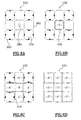
- Figures 1A to 1C illustrate three types of keyboards belonging to the prior art. These three keyboards are made to the same dimensions and the spacing E between the centers of two neighboring keys is constant from one keyboard to another. Only the width of the keys, noted respectively 1 A , 1 B and 1 C , varies from one keyboard to another. However, it is this dimension of the keys that plays a very large role on the value the margin of error enjoyed by a user around the center of a key on a keyboard.
- the margin of error is defined geometrically as the size of a horizontal, or vertical, segment on which the center of the finger must be for the keystroke to be valid. This margin is in fact inversely proportional to the typing precision.
- the value of the spacing E between the centers of two neighboring keys, for reduced-size keyboards intended for pocket devices is between 1 and 1.5 cm.
- FIGS. 1A to 1C show the evolution of the margin of error, denoted m A , m B and m C , as a function of the width of the keys. It appears that when the width l C of the keys is equal to E, the margin of error m C is minimal, that is to say that a user must exercise great vigilance not to knock on two keys simultaneously.
- FIG. 1B illustrates an intermediate case where the value of l B is between E and Ed.
- the present invention makes it possible to solve all these problems since it proposes a flat mechanical keyboard, intended to be integrated into a pocket electronic device, comprising secondary keys between the main keys.
- These secondary keys are movable and driven downwards by the main keys, when these themselves are driven downwards at the time of typing by the finger of a user.
- These secondary keys thus make it possible to increase the typing surface and considerably improve the comfort of typing since the finger is never in contact with at least one angular edge of the main key.
- such a keyboard having a flat surface allows better readability of the symbols which are written on the keyboard between two main contiguous keys.
- the keys being in relief, when using the keyboard in an oblique position relative to the line of vision of the eye of a user, such symbols are partially obscured by the keys in relief.
- FIG. 2 illustrates a first embodiment of a keyboard according to the invention designated by the reference 10.
- This keyboard comprises main keys denoted P which are ordered in matrix form. These main keys are separated from each other by mobile intermediate spaces also called secondary keys and denoted S.
- Each P key is therefore surrounded by four S keys.
- the P key is mechanically linked to the four S keys that surround it, but it is entirely conceivable to produce a keyboard in which each key P is mechanically linked to only one, or two or three secondary keys.
- the secondary keys have a hexagonal surface, but this shape is not essential and they can have surfaces of any other shape.
- the main P and secondary S keys are preferably at the same level so that the surface of the keyboard at rest is completely flat.
- the four main functions for operating the keys of a conventional keyboard are guiding the keys in their vertical movement, the reaction force making it possible to return the keys to the high position, blocking the keys in the high position, and the electrical contact. .
- the first two functions listed are performed by means of drive mechanisms.
- each of these drive mechanisms is placed under each of the keys.
- these drive mechanisms are advantageously distributed between the main keys P and the secondary keys S. This distribution thus allows each main key P to drive its four adjacent secondary keys downwards under the 'action of a pressure, and conversely each secondary key S exerts a restoring force so as to bring its two adjacent main keys to the high position when no pressure is exerted on them.
- the striking surface of a P key is increased and includes not only the main P key but also the four keys neighboring secondary S.
- This striking surface is designated by the reference 20 in FIG. 2, it is octagonal and delimited by a thick black line.
- This surface being flat, when a user taps on the corresponding main key P, even if his finger overlaps one or more neighboring secondary keys S, he remains in contact with a flat surface, and does not rub, as on conventional keyboards, on an angular edge of the fingerboard.
- the problem of friction against an angular edge being avoided, the size of the main keys can be as small as desired.
- the striking zone 20 thus created makes it possible to considerably reduce the number of typing errors likely to occur. Typing of a text can then be carried out for a long time, without any discomfort for the user.
- the size of the main keys is such that it makes it possible to minimize typing precision, that is to say to increase the margin of error from which a user benefits around the center of a P key.
- the keys P can, without drawbacks, be smaller than the contact surface of a finger since the secondary keys make it possible to maintain a flat typing surface.
- the width 1 of the main keys P is preferably between E, that is to say the value of the spacing between the centers of two contiguous keys P, and Ed.
- their surface is between 0.04 and 1 cm 2 .
- this surface can always be enlarged, and can for example reach a value equal to 1.5 cm 2 .
- the secondary keys S are small enough that a "random" keystroke always results in the setting moving at least one main key, regardless of the typing area. Consequently, the width of the secondary keys must be less than or equal to the diameter d of the contact surface of a finger. It is, for example, between approximately 0.2 cm and 0.7 cm.
- FIGS. 3A and 3B show the drive mechanisms and their distribution under the two types of keys S and P of the keyboard of FIG. 2.
- FIG. 3A represents a sectional view of the keys at rest, that is to say say in the high position
- FIG. 3B represents a sectional view of the keys when they are pressed under the action of a pressure exerted on a main key.
- the main and secondary keys rest on a base 30.
- the two types of key have common guide means 31.
- the guide means 31 comprise at their upper end two lugs 32. These lugs 32 constitute upward locking means. They each act on the cylinder 43 of a main key, which is located between the guide means 31 of this key, so as to block it at the end of the race, when the main key rises to the high position under the action of forces. of recall carried out under the secondary keys.
- Elastic means 34 such as springs for example, are provided only under the secondary keys S so that they exert the restoring force f r intended to return the neighboring main keys to the high position.
- electrical contacts 35 are provided only under the main keys P to allow the writing of the corresponding characters written on these keys to be controlled. In principle, it is preferable not to provide contact under the secondary keys S since these are not intended to control the writing of characters but only to increase the typing area.
- the secondary keys S are in the form of an inverted U and have, at each end of the branches of the U, a tongue 41 for supporting the neighboring keys P. These tongues 41 thus make it possible to drive the main keys which they support towards the high position, under the action of the restoring force fr exerted by the spring 34.
- the main keys P are in the form of a T and have, at each end of the horizontal bar of the T, a tongue 42.
- Each tongue 42 rubs on the one hand against a guide means 31, so as to ensure a good vertical hold of the button P when it is pressed, and also presses on a tongue 41 of a neighboring button S so as to drive this button S downwards when a pressure is exerted on the main button .
- These tongues 41 and 42 therefore make it possible to mechanically connect a main key P to one or more secondary keys S.
- FIG. 3B illustrates what happens when a pressure, designated by the letter F and represented by an arrow, is exerted on the central key P.
- the tabs 42 of the P key then press the tabs 41 of the neighboring S keys.
- the P key is pressed and therefore carries with it the neighboring secondary keys defining the striking zone while the other two keys P, located on either side of this striking zone, remain in the high position since no pressure is exerted there.
- the key P pressed then establishes contact with the electrical contacts 35 so as to control the writing of the character which corresponds to it.
- the springs 34 placed under the secondary keys of the striking zone are compressed and exert a restoring force f r . This restoring force f r allows, when the pressure F is removed, to bring the key P pressed in the high position.
- FIG. 4 illustrates a second embodiment of a keyboard according to the invention designated by the reference 100.
- This keyboard also includes main keys denoted P ′ ordered in matrix form.
- These keys P ' are separated from each other by mobile intermediate spaces.
- These mobile intermediate spaces are of two kinds: there are rectangular spaces called secondary keys, noted S ', and square spaces called tertiary keys, noted T.
- Each tertiary key T is framed by four secondary keys S' and four main keys P ', the S' keys sharing the sides of the T key, and the P 'keys sharing the corners.
- the shapes of the keys S ′ and T are not limited to the rectangular and square shapes, they depend in particular on the shape of the main keys as well as on their arrangement which is not necessarily matrix.
- the P ', S' and T keys are all on the same level so that the keyboard surface is flat.
- the key drive mechanisms are distributed between the three types of keys. Consequently, when a user presses a key P ', the latter carries with it, in its vertical movement, the corresponding striking zone defined by the four adjacent keys S' and the four adjacent keys T. This striking zone is highlighted by a thick black line and designated by the reference 200 in FIG. 4.
- the drive mechanisms are more particularly arranged so that the main key P 'drives down the adjacent secondary keys S' which are mechanically connected to it and which in turn drive the four neighboring tertiary keys T which are mechanically connected to them .
- the four tertiary keys T exert a restoring force at each corner of the striking zone and drive up the four neighboring keys S' which are mechanically connected and which in turn cause the key P 'which they frame and to which they are mechanically connected.
- Locking means make it possible to block the movement in elevation of the main key and to stabilize it in the high position.
- the key P ' also makes it possible to block the elevation of the secondary keys S', which in turn block the elevation of the keys T, so that all the keys P ', S' and T are stabilized in one position identical high giving the keyboard a flat surface.
- the width of the keys P ′ is of the same order of magnitude as that of the keys P of the keyboard 10 according to the first embodiment.
- the dimensions of the secondary S 'and tertiary T keys are also small enough that none of them can be driven downwards by the finger of a user without at least one of the main keys P' being as well.
- FIGS. 5A and 5B respectively represent a sectional view A-A and a sectional view B-B of the keyboard 100 of FIG. 4.
- FIG. 5A more particularly illustrates the relationship between a main key P 'and two neighboring keys S'. These two types of keys have common 360 guide means. Of course, in an alternative embodiment, these guide means can be specific to each type of key.
- the guide means 360 comprise, at their upper end, blocking means 370 against which abuts the lower end 403 of the main button P 'when the latter rises in the high position.
- the main key P ' has tongues 420 able to push on the tongues 410 of the secondary keys S' so as to drive them downwards, and to ensure the vertical maintenance of the key P 'by rubbing against the guide means 360.
- the tongues 410 of the keys S ' make it possible to push on the tongues 420 of the key P' in order to bring the latter to the high position.
- These tongues 410 and 420 make it possible to mechanically connect a key P 'to one or more secondary keys S'.
- Electrical contacts 350 are provided on the base 300, under the key P '.
- FIG. 5B illustrates the relationship between a tertiary key T and two neighboring secondary keys S '.
- the two types of keys have common guide means 380.
- An elastic means 390 such as a spring for example, is placed under the key T.
- the keys S ′ have tongues 415 capable of pushing on tongues 430 of the key T so as to drive the latter down, and ensuring a vertical hold of the key S 'by rubbing against the guide means 380.
- the spring 390 exerts a restoring force f r .
- the restoring force f r allows the tongues 430 of the key T to push on the tongues 415 of the keys S' in order to raise them to the high position.
- These tongues 415 and 430 make it possible to mechanically connect a secondary key S 'to one or more tertiary key (s) T.
- the keys S' then carry with them the key P 'by means of their tongues 410.
- FIGS. 6A to 6D make it possible to better understand the structure of the keyboard 100 since they represent top views of a part of this keyboard at different stages of its manufacture.
- FIG. 6A represents the guide means 360 common to the keys P 'and S', the guide means 380 common to the keys S 'and T, the blocking means 370 of the main keys P' and the spring 390 making it possible to exercise the restoring force under a tertiary touch.
- FIG. 4D illustrates the final stage of manufacture, when the main keys P 'are placed in their housings.
- the resistance to typing is only 1.5 times greater than that presented by the keyboard during the typing of a single key since the new typing zone contains 6 tertiary keys against 4 for the typing zone of a single key P '.
- the resistance ratio is higher since it is 1.75. Indeed, in this case the typing area of two P keys includes 7 secondary keys while the typing area of a single P key includes 4.
- FIGS. 7A to 7D illustrate an alternative embodiment of this keyboard 100.
- This variant consists in slightly tilting the contact zones between the main keys and the secondary keys and, similarly, between the secondary keys and the tertiary keys. This allows, when a main key P 1 is struck and the corresponding typing zone is pressed, the sixteen neighboring main and secondary keys to switch slightly towards the typing zone, and to simulate an elastic deformation of these keys framing the striking zone during the movement of the latter. Furthermore, this tilting of the sixteen keys adjacent to the typing zone offers a slightly concave shape complementary to the convex shape of a finger.
- FIG. 7C shows the keys P 1 and S 1 when they are fully pressed. In this case, an additional force f 5 exerted by S 1 on the button P 2 makes it possible to stabilize the latter in its inclined position.
- FIGS. 7A and 7D show the three types of keys at rest, when all the pairs of forces (f 1 , f 3 ) and (f 2 , f 4 ) are balanced.
- This variant embodiment has a great advantage.
- the position of the finger striking a striking zone is sufficiently offset at the time of striking so that it touches one of the main keys adjacent to the striking zone, after the rocking of this key, the oblique position that it will have acquired prevent an electrical contact can take place at the end of the race with the contacts 350 placed on the base 300 of the keyboard. Consequently, the margin of error available to typing is further increased.
- the shape of the surface of the S and T keys defining the intermediate space is not essential, it can be either hexagonal, square, cruciform or other. It is this form which determines the number of secondary keys and / or tertiary in relation to the number of main keys.
- FIG. 8 which illustrates a variant of a keyboard, the number of cruciform secondary keys is equal to the number of main keys.
- the number of keys S mechanically linked to a key P and the number of keys T mechanically linked to a key S are also not essential. They are at least equal to 1. In the examples cited in the description these numbers were maximum and equal respectively to the number of keys S framing a key P and to the number of keys S framing a key T.
- the shape of the main keys is also not limited to the square, it can also be circular, hexagonal or lozenge for example.
- An alternative embodiment also consists in slightly undulating the surface of the keyboard so as to improve the typing comfort.
- the main keys have a slightly concave shape, complementary to that of the finger.
- the secondary keys, and the tertiary keys when provided have a convex shape so that there is no break in slope.
- the surface of the keyboard therefore has a doubly wave-like appearance, along the vertical and horizontal axes; the horizontal axis being defined by the axis passing through the keyboard from left to right and the vertical axis being defined by the axis passing through the keyboard from top to bottom.
- Another alternative embodiment consists in uniting all the intermediate space between the main keys in a single secondary key capable of being driven downwards by each of the main keys.
- This unique secondary key is brought up by several springs, for example at its four ends.
- the main keys are also equipped with springs, of low intensity, so that the keys which are not pressed at the time of typing remain in the high position.
- the advantage of this variant is simplicity since the impact resistance is practically independent of the number of main keys struck simultaneously due to the high resistance linked to the secondary key.
- it has the disadvantage of offering a greater inertia at the time of striking and setting in motion of the secondary key, that is to say that it requires a greater energy of striking on the part of the user.
- k would have to be equal to 2 but this case is impossible since k must remain less than [(l + 1) * (c + 1)] / (l * c) where l and c are respectively the number of rows and columns of the keyboard and [(l + 1) * (c + 1)] the number of secondary keys, so that the total force attracting the keyboard at rest down is not greater to the force that pushes it up.
- such an embodiment also makes it possible, in the case where the contact zones between the keys are inclined, to considerably increase the lever force causing the keys adjacent to the striking zone towards the latter. Indeed, the springs in extension attract these keys downward and have more of a lever arm much larger than that which has the force f2 exerted by the key S2 of the keyboard of FIG. 7B.
Landscapes
- Input From Keyboards Or The Like (AREA)
Applications Claiming Priority (2)
| Application Number | Priority Date | Filing Date | Title |
|---|---|---|---|
| FR9605515A FR2748345B1 (fr) | 1996-05-02 | 1996-05-02 | Clavier mecanique plan |
| FR9605515 | 1996-05-02 |
Publications (2)
| Publication Number | Publication Date |
|---|---|
| EP0805465A1 true EP0805465A1 (de) | 1997-11-05 |
| EP0805465B1 EP0805465B1 (de) | 2000-08-16 |
Family
ID=9491780
Family Applications (1)
| Application Number | Title | Priority Date | Filing Date |
|---|---|---|---|
| EP97400991A Expired - Lifetime EP0805465B1 (de) | 1996-05-02 | 1997-05-02 | Flache mechanische Tastatur |
Country Status (4)
| Country | Link |
|---|---|
| US (1) | US5861588A (de) |
| EP (1) | EP0805465B1 (de) |
| DE (1) | DE69702808T2 (de) |
| FR (1) | FR2748345B1 (de) |
Cited By (3)
| Publication number | Priority date | Publication date | Assignee | Title |
|---|---|---|---|---|
| FR2953037A1 (fr) * | 2009-11-26 | 2011-05-27 | Jean Loup Claude Gillot | Clavier plat, mecanique et tactile |
| FR2955423A1 (fr) * | 2010-01-21 | 2011-07-22 | Gillot Jean Loup Claude | Clavier mecanique et tactile |
| FR2964760A1 (fr) * | 2010-09-15 | 2012-03-16 | Jean Loup Claude Gillot | Clavier plat dote a la fois de proprietes mecaniques et tactiles |
Families Citing this family (11)
| Publication number | Priority date | Publication date | Assignee | Title |
|---|---|---|---|---|
| US7265745B1 (en) * | 2000-04-27 | 2007-09-04 | Intel Corporation | Compact alphanumeric keyboard |
| ATE289115T1 (de) * | 2000-05-22 | 2005-02-15 | Digit Wireless Llc | Eingabegeräte und ihre verwendung |
| CA2412243C (en) * | 2001-11-23 | 2007-03-20 | Research In Motion Limited | Keyboard assembly for a mobile device |
| US7126498B2 (en) * | 2002-02-27 | 2006-10-24 | Digit Wireless, Llc | Keypad construction |
| BR0311243A (pt) * | 2002-05-23 | 2005-05-10 | Digit Wireless Llc | Teclados e comutadores de teclas |
| US20060119581A1 (en) * | 2002-09-09 | 2006-06-08 | Levy David H | Keyboard improvements |
| DE10257070B4 (de) * | 2002-12-06 | 2004-09-16 | Schott Glas | Verfahren zur automatischen Bestimmung einer gültigen oder ungültigen Tasteneingabe |
| US7218247B2 (en) * | 2003-08-21 | 2007-05-15 | Chiou-Haun Lee | Brief numerical keypad and its output method |
| US7953448B2 (en) * | 2006-05-31 | 2011-05-31 | Research In Motion Limited | Keyboard for mobile device |
| US20060291936A1 (en) * | 2005-06-28 | 2006-12-28 | Perez Suni V | Resource expander key |
| US8183478B2 (en) | 2009-10-26 | 2012-05-22 | Research In Motion Limited | Key assembly for an electronic device having a connected keycap |
Citations (1)
| Publication number | Priority date | Publication date | Assignee | Title |
|---|---|---|---|---|
| DE2729157A1 (de) * | 1977-06-28 | 1979-01-04 | Widmaier Fa Hans | Tastenanordnung |
Family Cites Families (5)
| Publication number | Priority date | Publication date | Assignee | Title |
|---|---|---|---|---|
| DE8302660U1 (de) * | 1983-02-01 | 1983-06-16 | Hans Widmaier Fabrik Fuer Apparate Der Fernmelde- Und Feinwerktechnik, 8000 Muenchen | Tastenanordnung zur Auslösung von bestimmten Symbolen der Tastenoberfläche jeweils zugeordneten Schaltfunktionen oder Schaltsignalen. |
| US4566078A (en) * | 1983-03-30 | 1986-01-21 | International Business Machines Corp. | Concurrent multi-lingual use in data processing systems |
| NL186072C (nl) * | 1987-06-30 | 1990-09-17 | Ava Consult Bv | Toetsenbord voor een woordschrijfmachine. |
| US5528235A (en) * | 1991-09-03 | 1996-06-18 | Edward D. Lin | Multi-status multi-function data processing key and key array |
| US5612690A (en) * | 1993-06-03 | 1997-03-18 | Levy; David | Compact keypad system and method |
-
1996
- 1996-05-02 FR FR9605515A patent/FR2748345B1/fr not_active Expired - Lifetime
-
1997
- 1997-04-30 US US08/846,619 patent/US5861588A/en not_active Expired - Lifetime
- 1997-05-02 DE DE69702808T patent/DE69702808T2/de not_active Expired - Lifetime
- 1997-05-02 EP EP97400991A patent/EP0805465B1/de not_active Expired - Lifetime
Patent Citations (1)
| Publication number | Priority date | Publication date | Assignee | Title |
|---|---|---|---|---|
| DE2729157A1 (de) * | 1977-06-28 | 1979-01-04 | Widmaier Fa Hans | Tastenanordnung |
Cited By (3)
| Publication number | Priority date | Publication date | Assignee | Title |
|---|---|---|---|---|
| FR2953037A1 (fr) * | 2009-11-26 | 2011-05-27 | Jean Loup Claude Gillot | Clavier plat, mecanique et tactile |
| FR2955423A1 (fr) * | 2010-01-21 | 2011-07-22 | Gillot Jean Loup Claude | Clavier mecanique et tactile |
| FR2964760A1 (fr) * | 2010-09-15 | 2012-03-16 | Jean Loup Claude Gillot | Clavier plat dote a la fois de proprietes mecaniques et tactiles |
Also Published As
| Publication number | Publication date |
|---|---|
| EP0805465B1 (de) | 2000-08-16 |
| DE69702808T2 (de) | 2001-02-22 |
| FR2748345A1 (fr) | 1997-11-07 |
| US5861588A (en) | 1999-01-19 |
| FR2748345B1 (fr) | 1998-07-17 |
| DE69702808D1 (de) | 2000-09-21 |
Similar Documents
| Publication | Publication Date | Title |
|---|---|---|
| EP0805465B1 (de) | Flache mechanische Tastatur | |
| EP0181905B1 (de) | Vorrichtung zur darstellung taktiler informationen | |
| EP0446088B1 (de) | Schalter mit Berührungseffekt und diesen Schalter verwendende Tastatur | |
| EP1211704B1 (de) | Betätigungsorgan mit drei aktiven Stellungen | |
| JP2002033030A (ja) | キースイッチ | |
| FR2917230A1 (fr) | Dispositif pour la commande d'un appareil electronique | |
| EP1271276A1 (de) | Steuervorrichtung für ein elektronisches Gerät | |
| EP1246431B1 (de) | Mobilfon mit verbesserter Steuertastatur | |
| EP1071106A1 (de) | Zweistufiger Druckschalter | |
| FR2899719A1 (fr) | Commutateur electrique a voies de commutation multiples | |
| EP0981798A1 (de) | Verbinder mit einziehbaren kontakten zum verbinden einer mikroschaltungskarte | |
| JP3480559B2 (ja) | キーボード装置 | |
| CH641590A5 (fr) | Dispositif de commutation formant bouton-poussoir ou clavier a touches enfoncables. | |
| KR970000597A (ko) | 잉크롤러장치와 잉크롤러장치를 구비한 넘버링머신 | |
| FR2554630A1 (fr) | Contacteur du type bouton-poussoir et son utilisation sur des claviers | |
| EP0832495B1 (de) | Vorrichtung zur einstellung der position für einen motorisch verstellbaren sitz | |
| EP1197980B1 (de) | Steuervorrichtung mit Taste | |
| JP3655449B2 (ja) | キーボード | |
| CN121041660B (zh) | 一种游戏手柄多用型摇杆结构 | |
| EP0280608A1 (de) | Gerät zur Darstellung reliefartiger Zeichen, insbesondere Brailleschriftzeichen | |
| EP0429113B1 (de) | Didaktisches Spielelement und Anordnung von solchen Elementen | |
| EP4388569A1 (de) | Handbediengerät mit einem torusförmigen element zur rückführung des bedienknopfes | |
| JP3068277U (ja) | キ―ボ―ドのパンタグラフ式キ― | |
| FR2964760A1 (fr) | Clavier plat dote a la fois de proprietes mecaniques et tactiles | |
| EP1691533B1 (de) | Handgerät mit Tasten mit mehreren Labels |
Legal Events
| Date | Code | Title | Description |
|---|---|---|---|
| PUAI | Public reference made under article 153(3) epc to a published international application that has entered the european phase |
Free format text: ORIGINAL CODE: 0009012 |
|
| AK | Designated contracting states |
Kind code of ref document: A1 Designated state(s): DE GB |
|
| 17P | Request for examination filed |
Effective date: 19971226 |
|
| 17Q | First examination report despatched |
Effective date: 19980708 |
|
| GRAG | Despatch of communication of intention to grant |
Free format text: ORIGINAL CODE: EPIDOS AGRA |
|
| GRAG | Despatch of communication of intention to grant |
Free format text: ORIGINAL CODE: EPIDOS AGRA |
|
| GRAH | Despatch of communication of intention to grant a patent |
Free format text: ORIGINAL CODE: EPIDOS IGRA |
|
| GRAH | Despatch of communication of intention to grant a patent |
Free format text: ORIGINAL CODE: EPIDOS IGRA |
|
| GRAA | (expected) grant |
Free format text: ORIGINAL CODE: 0009210 |
|
| AK | Designated contracting states |
Kind code of ref document: B1 Designated state(s): DE GB |
|
| GBT | Gb: translation of ep patent filed (gb section 77(6)(a)/1977) |
Effective date: 20000816 |
|
| REF | Corresponds to: |
Ref document number: 69702808 Country of ref document: DE Date of ref document: 20000921 |
|
| PLBE | No opposition filed within time limit |
Free format text: ORIGINAL CODE: 0009261 |
|
| STAA | Information on the status of an ep patent application or granted ep patent |
Free format text: STATUS: NO OPPOSITION FILED WITHIN TIME LIMIT |
|
| 26N | No opposition filed | ||
| REG | Reference to a national code |
Ref country code: GB Ref legal event code: IF02 |
|
| PGFP | Annual fee paid to national office [announced via postgrant information from national office to epo] |
Ref country code: DE Payment date: 20110531 Year of fee payment: 15 |
|
| REG | Reference to a national code |
Ref country code: DE Ref legal event code: R119 Ref document number: 69702808 Country of ref document: DE Effective date: 20121201 |
|
| PG25 | Lapsed in a contracting state [announced via postgrant information from national office to epo] |
Ref country code: DE Free format text: LAPSE BECAUSE OF NON-PAYMENT OF DUE FEES Effective date: 20121201 |
|
| PGFP | Annual fee paid to national office [announced via postgrant information from national office to epo] |
Ref country code: GB Payment date: 20160426 Year of fee payment: 20 |
|
| REG | Reference to a national code |
Ref country code: GB Ref legal event code: PE20 Expiry date: 20170501 |
|
| PG25 | Lapsed in a contracting state [announced via postgrant information from national office to epo] |
Ref country code: GB Free format text: LAPSE BECAUSE OF EXPIRATION OF PROTECTION Effective date: 20170501 |