EP0805584B1 - Composeur d'image à tambour interne virtuel entraíné par cabestan - Google Patents
Composeur d'image à tambour interne virtuel entraíné par cabestan Download PDFInfo
- Publication number
- EP0805584B1 EP0805584B1 EP19970102689 EP97102689A EP0805584B1 EP 0805584 B1 EP0805584 B1 EP 0805584B1 EP 19970102689 EP19970102689 EP 19970102689 EP 97102689 A EP97102689 A EP 97102689A EP 0805584 B1 EP0805584 B1 EP 0805584B1
- Authority
- EP
- European Patent Office
- Prior art keywords
- media
- recording
- image
- curved support
- imaging
- Prior art date
- Legal status (The legal status is an assumption and is not a legal conclusion. Google has not performed a legal analysis and makes no representation as to the accuracy of the status listed.)
- Expired - Lifetime
Links
- 238000003384 imaging method Methods 0.000 claims description 39
- 230000032258 transport Effects 0.000 claims description 15
- 238000000034 method Methods 0.000 claims description 11
- 230000003287 optical effect Effects 0.000 claims description 11
- 230000008901 benefit Effects 0.000 description 4
- 230000007246 mechanism Effects 0.000 description 3
- 230000001934 delay Effects 0.000 description 2
- 230000007704 transition Effects 0.000 description 2
- XAGFODPZIPBFFR-UHFFFAOYSA-N aluminium Chemical compound [Al] XAGFODPZIPBFFR-UHFFFAOYSA-N 0.000 description 1
- 229910052782 aluminium Inorganic materials 0.000 description 1
- 230000005540 biological transmission Effects 0.000 description 1
- 238000003754 machining Methods 0.000 description 1
- 238000005096 rolling process Methods 0.000 description 1
- 239000000126 substance Substances 0.000 description 1
- 230000007723 transport mechanism Effects 0.000 description 1
Images

Classifications
-
- H—ELECTRICITY
- H04—ELECTRIC COMMUNICATION TECHNIQUE
- H04N—PICTORIAL COMMUNICATION, e.g. TELEVISION
- H04N1/00—Scanning, transmission or reproduction of documents or the like, e.g. facsimile transmission; Details thereof
- H04N1/04—Scanning arrangements, i.e. arrangements for the displacement of active reading or reproducing elements relative to the original or reproducing medium, or vice versa
- H04N1/06—Scanning arrangements, i.e. arrangements for the displacement of active reading or reproducing elements relative to the original or reproducing medium, or vice versa using cylindrical picture-bearing surfaces, i.e. scanning a main-scanning line substantially perpendicular to the axis and lying in a curved cylindrical surface
- H04N1/0607—Scanning a concave surface, e.g. with internal drum type scanners
- H04N1/0621—Scanning a concave surface, e.g. with internal drum type scanners using a picture-bearing surface stationary in the main-scanning direction
- H04N1/0635—Scanning a concave surface, e.g. with internal drum type scanners using a picture-bearing surface stationary in the main-scanning direction using oscillating or rotating mirrors
-
- H—ELECTRICITY
- H04—ELECTRIC COMMUNICATION TECHNIQUE
- H04N—PICTORIAL COMMUNICATION, e.g. TELEVISION
- H04N1/00—Scanning, transmission or reproduction of documents or the like, e.g. facsimile transmission; Details thereof
- H04N1/04—Scanning arrangements, i.e. arrangements for the displacement of active reading or reproducing elements relative to the original or reproducing medium, or vice versa
- H04N1/06—Scanning arrangements, i.e. arrangements for the displacement of active reading or reproducing elements relative to the original or reproducing medium, or vice versa using cylindrical picture-bearing surfaces, i.e. scanning a main-scanning line substantially perpendicular to the axis and lying in a curved cylindrical surface
- H04N1/0607—Scanning a concave surface, e.g. with internal drum type scanners
-
- H—ELECTRICITY
- H04—ELECTRIC COMMUNICATION TECHNIQUE
- H04N—PICTORIAL COMMUNICATION, e.g. TELEVISION
- H04N1/00—Scanning, transmission or reproduction of documents or the like, e.g. facsimile transmission; Details thereof
- H04N1/04—Scanning arrangements, i.e. arrangements for the displacement of active reading or reproducing elements relative to the original or reproducing medium, or vice versa
- H04N1/06—Scanning arrangements, i.e. arrangements for the displacement of active reading or reproducing elements relative to the original or reproducing medium, or vice versa using cylindrical picture-bearing surfaces, i.e. scanning a main-scanning line substantially perpendicular to the axis and lying in a curved cylindrical surface
- H04N1/0664—Scanning arrangements, i.e. arrangements for the displacement of active reading or reproducing elements relative to the original or reproducing medium, or vice versa using cylindrical picture-bearing surfaces, i.e. scanning a main-scanning line substantially perpendicular to the axis and lying in a curved cylindrical surface with sub-scanning by translational movement of the picture-bearing surface
Definitions
- Imagesetting and platesetting devices are available in flatbed, internal drum, external drum, and capstan-type engine configurations. Each configuration offers varying features and benefits, depending on the demands of the user.
- the user's demands such as image quality and resolution, printing run length, and work flow volume or output speed can determine the best configuration for the job.
- the recording media is in a web form and has a continuous motion through the device so that imaging occurs without delays for media loading and unloading.
- an advantage is realized because of the symmetry of the internal drum, in a relatively simple and inexpensive optical system compared to an optical system in a capstan system.
- Typical capstan systems require an expensive F-theta lens to allow the scanned beam to be focused across the flat scan line.
- US 1,792,264 describes an apparatus for the transmission of pictures having two spaced-apart members between which a receiving sheet is supported, with the two members extending lengthwise over a certain distance of the receiving sheet transport path and an exposure takes place at the end of the member, i.e. at the transition from the area from which the receiving sheet is guided between the two members into the area in which the receiving sheet extends without guidance, see Fig. 2 therein.
- Fig. 5 therein a further variant may be gathered in which the receiving sheet is brought into the desired shape through a slot in the bottom of a cabinet with the exposure of the receiving sheet equally taking place when the guided area is left.
- the object of the invention to provide an inexpensive imaging device for outputting images from electronic files onto film, paper, plate material, or other image recording media providing images with improved quality as well as a corresponding method.
- This task is solved by an imaging system with the features of claim 1 as well as by a method for recording an image with the features of claim 7.
- the present invention provides a method and apparatus for recording an image onto a web-type image recording media.
- the invention comprises a media transport system for transporting web-type image recording media through the imaging system and a media imaging station for recording an image onto the media.
- the media imaging station includes a curved support which supports the media and forms the media into a virtual drum.
- the media imaging station includes a scanning mechanism for scanning a modulated image recording beam across the virtual drum in a scan line.
- the media transport system transports the media relative to the curved support during scanning by the scanning mechanism to form a series of adjacent scan lines.
- the present invention further provides an electronic prepress apparatus/method including a computer workstation for creating, previewing, storing and transferring electronic image files to be outputted onto recording media.
- the workstation controls other components of the electronic prepress system, which can include an image processor for converting the electronic image files transferred from the computer workstation into digital data files.
- An output device for outputting the digital data files onto recording media in a form of images previewed on said computer means, includes a media transport mechanism for transporting recording media along a media path, a curved support for supporting the media and forming the media into a virtual drum having an axis parallel to the media path, and a scanning apparatus for scanning a modulated recording beam representing the digital data files across the virtual drum in a scan line.
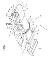
- a capstan driven virtual internal drum imaging system is shown, generally indicated as 10, according to the present invention.
- the imaging system 10 has a media supply station 12, a media tensioning station 14, an imaging station 16, a capstan drive 18, a media cutter 20, and a media take-up station 22.
- Web type image recording media 24 is used in the imaging system 10 and can be paper, film, or plate type material.
- the media supply station 12 contains a supply roll of the media 24 which is supported on a roll shaft 28 which has a drive gear 30 on the outer end of the shaft 28.
- the drive gear 30 is driven by a motor 32 which rotates the drive gear 30 through a motor gear 34 connected to the motor shaft 36.
- the media 24 is fed through the tensioning station 14 which includes a series of rollers 38, 40, 42, which rotate freely about their respective roller shafts 44, 46, 48.
- a tensioning spring 50 is connected to the shaft 46 of roller 40.
- Roller 40 is vertically adjustable relative to the other rollers 38, 42 and relative to a support frame (not shown) to accommodate and control slack or tension in the media 24.
- the tensioning station 14 works in cooperation with the drive motor 32 during start and stop sequences to control the media and absorb torque disturbances.
- the spring has a tension measuring gauge to measure the tension or slack in the media. The gauge provides feedback to the media supply drive motor 32 to control the output torque of the drive motor 32 according to the amount of tension in the media.
- the imaging station 16 includes a curved media platen 52 which has an upper surface 54 and a lower surface 56 between which the media 24 passes.
- a space 57 is provided between the upper and lower surfaces 54, 56 for the media 24, the space being a few mils thicker than the thickness of the media 24.
- the curved media platen 52 can be provided with a mechanism to adjust the space 57 between the upper and lower surfaces 54, 56, such as with a precision screw and nut assembly on the outer ends of the platen (not shown), to accommodate varying thicknesses of media 24.
- the lower surface 56 is provided with a slot 58 through which the media 24 is imaged.
- the media 24 is curved by the platen 52 creating a radius of curvature R in the media with a center of curvature C to form a virtual drum for optimal imaging according to the present invention.
- the curved media platen 52 is shown having a relatively narrow width in the preferred embodiment of the invention.
- the width of the platen 52 in the direction of the media motion can be larger, and that the curvature of the media platen need not be uniform over the width of the platen.
- the platen can have a very large radius of curvature at the entrance and exit of the media plate so as to be flat at the entrance and exit, and to have a relatively small radius of curvature at the center of the media plate at the area of the media plate to form the virtual drum in the media where the media is imaged, and having smooth transitional areas between the entrance, center, and exit of the media platen to allow smooth passing of the media through the platen without rippling of the media.
- several narrow media platens may be spaced apart along the media path. In all these variations the virtual drum is formed in the media.
- a laser scanning system 60 is positioned below the curved media platen 52.
- a laser source 62 generates a beam 64 which is focused by an optical element 66 onto a reflective spinner 68.
- the spinner 68 is rotated by spin motor 70 to scan the reflected beam 72 across the virtual drum of the media 24 through slot 58 of the lower surface 56 of the media platen 52 in a scanline.
- the center of curvature C of the virtual drum is the same point that the beam 64 encounters the reflective spinner 68.
- the distance the beam travels from the spinner to the media at the slot is uniform during rotation of the spinner through an angle during which the beam scans the media.
- the beam spot focus remains uniform as a result.
- the laser source 62 is modulated on and off by an acoustic-optical modulator 74, hereinafter AOM.
- AOM acoustic-optical modulator
- the media motion is continuous during beam scanning to write successive lines of half-tone dots onto the media to form a continuous image.
- Motion of the media is primarily controlled by the capstan drive 18.
- the capstan drive 18 has a pair of nip rollers 76, 78 which are driven by drive motor 80. The nip rollers are pinched together in rolling contact so that motion is transmitted from the driven roller 76 to the other roller 78 upon its rotation.
- the capstan drive 18 accurately controls the media motion to synchronize the advancement of the media 24 though the imaging station 16 with the laser scanning system 60 in the following manner.
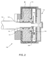
- an integrated rotary drive apparatus 100 is shown as the preferred embodiment for a connection between the drive motor 80 and nip roller shaft 82 of the capstan drive 18.
- the integrated rotary drive apparatus 100 has a closed loop electronic feedback controller which varies the torque output from the motor 80 for the purpose of rotating the nip roller 76 in a controlled manner.
- the nip roller shaft 82 is supported within a hollow shaft 102 of the motor 80 supported by bearings 104, 106.
- the bearings are contained within a motor case 108.
- an inertia flywheel 110 and a rotary optical encoder disk 112 which rotate with the hollow shaft 102 and with the nip roller shaft 82.
- the roller shaft 82 is mechanically coupled to the hollow shaft 102 as well as to the motor armature assembly, generally shown as 114.
- An optical encoder reader 116 is also contained and fixed within the casing 108.
- the optical encoder disk 112 when aligned with encoder reader 116 provides electrical feedback to a closed loop electronic control system.
- the feedback comprises an electronic signal representative of the angular position and velocity of hollow shaft 200.
- the feedback signal is used to control the output torque of the DC motor 80 to provide motion control of the nip roller 76. Additional details of the integrated rotary drive apparatus are provided in U.S. Patent 5,450,770.
- the tensioning station 14 and the capstan drive 18 are important to the invention to keep the media 24 taught during media motion through the curved media platen 52.
- the tensioning system 14 provides a force pulling the media tight in the reverse direction of the media motion, to the left as viewed in Fig. 1, while the capstan drive motor 80 and nip rollers 76, 78 provide a force pulling the media to the right as viewed in Fig. 1.
- This allows for the media 24 to smoothly transition from a flat profile at the rollers 42 and 76, 78, to the curved profile in the media platen 52 with a radius of curvature R, without rippling of the media in the areas between the rollers and the platen 52.
- an electronic prepress system 200 is depicted showing the output device 10 according to the present invention in connection with a workstation 202, a raster image processor (RIP) 204, and an on-line processor 206.
- the workstation 202 is used to create, store, preview and transfer electronic files of images, and to control other components of the electronic prepress system 200.
- the workstation transfers the electronic files to the RIP 204 for digitizing, i.e. converting the electronic files into digital images which can be understood by the output device 10 and sent through the AOM 74 for output.
- the output device 10 has a controller 220 which controls the commands and signals to the supply drive motor 32, the spin motor 68, and the capstan drive motor 80.
- a feedback loop 222 is shown from the media tension sensor 224 to the controller 220 which provides feedback to the supply drive motor 32 to control the output torque of the drive motor 32 according to the amount of tension in the media.
- the controller 220 synchronizes the control of the spin motor 68 and the AOM 74, as indicated by loop 226.
- the closed loop electronic control system 228 is shown for the integrated rotary drive apparatus 100, as previously described, wherein the optical encoder 116 provides feedback to the controller 220 to control the output torque of the capstan drive motor 80.
- Information is exchanged between the RIP 204 and the output device 10, as well as between the output device 10 and the processor 206.
- the media 24 is moved past the media cutter 20 and into the take-up station 22.
- a take-up cassette 82 collects the media 24.
- the media cutter can be selectively activated by an operator or it can be controlled by the output device controller 220, to cut the media between jobs or accumulate successive jobs and cut when the cassette is full.
- the take-up station may comprise an on-line processing device 206, as depicted in Fig. 3, when the media outputted from the present invention requires additional processing, whether it be chemical "wet" processing or mechanical "dry” type processing.
- curved media platen described with reference to Fig. 1 curves the media into a partial cylinder having a uniform radius of curvature.
- configuration of the media platen may be other than that described herein and the optical system may be designed to accommodate such other configurations to obtain accurate and focused imaging on the media.
Landscapes
- Engineering & Computer Science (AREA)
- Multimedia (AREA)
- Signal Processing (AREA)
- Exposure And Positioning Against Photoresist Photosensitive Materials (AREA)
- Handling Of Sheets (AREA)
- Projection-Type Copiers In General (AREA)
- Paper Feeding For Electrophotography (AREA)
- Facsimile Scanning Arrangements (AREA)
- Printers Or Recording Devices Using Electromagnetic And Radiation Means (AREA)
- Electrophotography Using Other Than Carlson'S Method (AREA)
Claims (14)
- Système d'imagerie pour enregistrer une image sur un support d'enregistrement d'image de type bande, comprenant :dans lequel ledit moyen de transport du support transporte le support relativement audit moyen d'appui incurvé afin de former une série de lignes de balayage adjacentes durant le balayage par ledit moyen de balayage,(a) un moyen de transport de support (18) pour transporter le support d'enregistrement d'image de type bande (24) à travers un système d'imagerie ; et(b) une station d'imagerie du support (16) pour enregistrer une image sur le support, ladite station d'imagerie du support comportant un moyen d'appui incurvé (52) dont l'axe est parallèle à la trajectoire du support, pour servir d'appui et pour mettre en forme le support, ladite station d'imagerie du support comportant un moyen de balayage (60) pour balayer un faisceau d'enregistrement d'image modulé sur ledit support, selon une ligne de balayage,
caractérisé en ce que
ledit moyen d'appui incurvé (52) comprend une surface supérieure (54) et une surface inférieure (56) adjacente à ladite surface supérieure, avec un espace (57) entre ladite surface supérieure et ladite surface inférieure, ledit support passant à travers ledit moyen d'appui incurvé dans ledit espace entre lesdites surfaces supérieure et inférieure, ladite surface inférieure dudit moyen d'appui incurvé possédant une fente (58) à travers laquelle passe le faisceau d'enregistrement pour imager ledit support. - Système selon la revendication 1, comportant en outre un moyen de mise sous tension du support (14) pour mettre sous tension le support tandis que ledit moyen de transport transporte le support à travers le système d'imagerie.
- Système selon la revendication 2, dans lequel ledit moyen de mise sous tension et ledit moyen de transport fournissent une rétroaction vers un régisseur (220) du système de façon à synchroniser la commande dudit moyen de mise sous tension avec celle dudit moyen de transport pour maintenir le support tendu au cours du transport à travers ledit moyen d'appui incurvé.
- Système selon l'une des revendications précédentes, dans lequel ladite surface supérieure (54) présente un rayon de courbure légèrement supérieur au rayon de courbure de ladite surface inférieure (56).
- Système selon l'une des revendications précédentes, dans lequel ledit moyen de balayage comporte une surface réfléchissante rotative (68) qui projette ledit faisceau d'enregistrement sur ledit support dans ladite ligne de balayage, ladite surface réfléchissante rotative étant située au centre (C) du rayon de courbure desdites surfaces supérieure et inférieure.
- Système selon l'une des revendications 2 à 5, dans lequel ledit moyen de transport comporte un moyen de codage optique (116) qui fournit une rétroaction vers ledit régisseur (220) du système et ledit moyen de mise sous tension comporte un détecteur de mise sous tension (224) qui fournit une rétroaction vers ledit régisseur du système.
- Procédé pour enregistrer une image sur un support d'enregistrement d'image de type bande, comprenant les étapes consistant à :transporter le support d'enregistrement d'image de type bande (24) à travers un système d'imagerie (10) ;donner appui au support, sous une forme incurvée, au niveau d'un moyen d'appui incurvé (52) d'une station d'imagerie (16) et former un rayon de courbure dans le support par passage dudit support à travers un espace (57) entre une surface supérieure (54) et une surface inférieure (56) dudit moyen d'appui incurvé, l'axe de courbure étant parallèle à la trajectoire du support ;balayer un faisceau d'enregistrement d'image modulé focalisé en travers dudit support au niveau de la station d'imagerie à travers une fente (57) dans la surface inférieure dudit moyen d'appui incurvé pour former une ligne de balayage ; ettransporter le support relativement à la station d'imagerie durant le balayage par ledit moyen de balayage pour former une série de lignes de balayage adjacentes.
- Procédé selon la revendication 7, comportant en outre l'étape consistant à mettre sous tension le support pendant le transport du support à travers la station d'imagerie.
- Procédé selon la revendication 8, comportant en outre l'étape consistant à réguler le transport du support et la mise sous tension du support à l'aide d'un régisseur (220) de système pour maintenir le support tendu durant le transport du support à travers le système.
- Procédé selon l'une des revendications 7 à 9, comportant en outre la transition régulière du support de type bande d'une forme plate, avant la station 'd'imagerie, à une forme incurvée au niveau du moyen d'appui incurvé (52) de la station d'imagerie et de nouveau à une forme plate après la station d'imagerie au fur et à mesure de son transport.
- Système de prépresse électronique comprenant :(a) un moyen informatique (202) pour créer, prévisualiser, stocker et transférer des fichiers d'images électroniques appelés à être sortis sur un support d'enregistrement (24), et pour commander au moins un autre composant du système de prépresse électronique ;(b) un moyen de traitement d'images (204) pour convertir les fichiers d'images électroniques transférés dudit moyen informatique en fichiers de données numériques ;(c) un moyen de sortie pour sortir lesdits fichiers de données numériques sur le support d'enregistrement sous la forme d'images prévisualisées sur ledit moyen informatique, ledit moyen de sortie comprenant un système d'imagerie selon l'une des revendications 1 à 6 dans lequel ledit moyen de transport du support (32, 80) transporte ledit support d'enregistrement le long d'une trajectoire du support, ladite surface incurvée présente un axe parallèle à la trajectoire du support, et ladite image modulée représente lesdits fichiers de données numériques.
- Système selon la revendication 11, comprenant en outre un moyen de traitement (206) pour traiter ledit support d'enregistrement fourni en sortie par ledit moyen de sortie.
- Procédé pour un système de prépresse électronique comprenant les étapes consistant à :(a) créer, prévisualiser, stocker et transférer sur une station de travail informatique (202) des fichiers d'images électroniques appelés à être sortis sur un support d'enregistrement (24),(b) commander au moins un autre composant du système de prépresse électronique depuis la station de travail informatique ;(c) convertir les fichiers d'images électroniques transférés dudit moyen informatique en fichiers de données numériques à l'aide d'un dispositif de traitement d'images (204) ;(d) sortir les fichiers de données numériques sur le support d'enregistrement sous la forme d'images prévisualisées sur la station de travail informatique à l'aide d'un moyen de sortie, le moyen de sortie exécutant les étapes consistant à transporter le support d'enregistrement le long d'une trajectoire du support, les étapes d'un procédé selon l'une des revendications 7 à 10, dans lequel ledit support reçoit un appui sur la trajectoire du support, ledit moyen d'appui incurvé présente un axe parallèle à la trajectoire du support, et ladite image modulée représente lesdits fichiers de données numériques.
- Procédé selon la revendication 13, comprenant en outre l'étape consistant à traiter le support d'enregistrement fourni en sortie par le dispositif de sortie au moyen d'un dispositif de traitement de support (206).
Applications Claiming Priority (4)
| Application Number | Priority Date | Filing Date | Title |
|---|---|---|---|
| US640308 | 1996-04-30 | ||
| US08/640,308 US5850248A (en) | 1996-04-30 | 1996-04-30 | Capstan driven virtual internal drum imagesetter |
| US08/640,048 US5835686A (en) | 1996-04-30 | 1996-04-30 | Electronic prepress system having a capstan driven virtual internal drum imagesetter |
| US640048 | 1996-04-30 |
Publications (3)
| Publication Number | Publication Date |
|---|---|
| EP0805584A2 EP0805584A2 (fr) | 1997-11-05 |
| EP0805584A3 EP0805584A3 (fr) | 1998-04-01 |
| EP0805584B1 true EP0805584B1 (fr) | 2001-09-12 |
Family
ID=27093468
Family Applications (1)
| Application Number | Title | Priority Date | Filing Date |
|---|---|---|---|
| EP19970102689 Expired - Lifetime EP0805584B1 (fr) | 1996-04-30 | 1997-02-19 | Composeur d'image à tambour interne virtuel entraíné par cabestan |
Country Status (3)
| Country | Link |
|---|---|
| EP (1) | EP0805584B1 (fr) |
| JP (1) | JPH1093775A (fr) |
| DE (1) | DE69706600T2 (fr) |
Families Citing this family (1)
| Publication number | Priority date | Publication date | Assignee | Title |
|---|---|---|---|---|
| GB9710011D0 (en) * | 1997-05-16 | 1997-07-09 | Hk Productions Ltd | Apparatus for moving a radiation beam across a medium |
Family Cites Families (4)
| Publication number | Priority date | Publication date | Assignee | Title |
|---|---|---|---|---|
| NL26337C (fr) * | 1928-03-26 | |||
| US3809806A (en) * | 1972-10-18 | 1974-05-07 | Columbia Broadcasting Syst Inc | Banding correction system for film recording apparatus |
| DE3318311A1 (de) * | 1983-05-19 | 1984-11-22 | Dr. Böger Photosatz GmbH, 2000 Wedel | Optische lichtfleck-abtastvorrichtung fuer ein photoempfindliches bahnmaterial bei optischen photosetzgeraeten |
| US4635108A (en) * | 1983-09-09 | 1987-01-06 | 501 Hazeltine Corporation | Scanner-previewer combination including a programmable sampling circuit for permitting an entire frame of an original to be stored in a fixed-capacity memory |
-
1997
- 1997-02-19 DE DE1997606600 patent/DE69706600T2/de not_active Expired - Fee Related
- 1997-02-19 EP EP19970102689 patent/EP0805584B1/fr not_active Expired - Lifetime
- 1997-04-10 JP JP9106803A patent/JPH1093775A/ja active Pending
Also Published As
| Publication number | Publication date |
|---|---|
| DE69706600D1 (de) | 2001-10-18 |
| DE69706600T2 (de) | 2002-06-06 |
| JPH1093775A (ja) | 1998-04-10 |
| EP0805584A3 (fr) | 1998-04-01 |
| EP0805584A2 (fr) | 1997-11-05 |
Similar Documents
| Publication | Publication Date | Title |
|---|---|---|
| US4967233A (en) | Fixed full width array scan head calibration apparatus | |
| FI84543B (fi) | Gruppobservationssystem. | |
| JP2000025996A (ja) | 画像プリント | |
| US5850248A (en) | Capstan driven virtual internal drum imagesetter | |
| EP1261193A1 (fr) | Appareil et méthode pour contrôler l'opération de lecture d'une plaque blanche de référence dans un dispositif de lecture d'images ayant un mécanisme de passage de feuilles | |
| EP0805584B1 (fr) | Composeur d'image à tambour interne virtuel entraíné par cabestan | |
| US5835686A (en) | Electronic prepress system having a capstan driven virtual internal drum imagesetter | |
| US5894342A (en) | Imagesetter | |
| JPH09151003A (ja) | 光ビーム走査露光装置 | |
| EP1024404A1 (fr) | Méthode et dispositif de transfert tampon de feuilles entre des components dans un système d'enregistrements d'images | |
| EP1395037A2 (fr) | Dispositif et méthode de calibrage d'un système d'imagerie pendant l'imagerie | |
| US5663554A (en) | Weak lens focus adjusting mechanism based upon thickness of scanned material and imagesetter using same | |
| US20040027413A1 (en) | Tractor feed imaging system and method for platesetter | |
| CA2374092A1 (fr) | Processus et appareil pour la production numerique d'une image | |
| JP3493726B2 (ja) | レーザ光走査装置 | |
| JP3198802B2 (ja) | 定着装置のニップ幅調整装置 | |
| US20030205639A1 (en) | Method and apparatus for buffer transfer of media sheets between components in an imaging system | |
| JP3769061B2 (ja) | 副走査搬送装置 | |
| US6160608A (en) | Image recording apparatus | |
| JP2872261B2 (ja) | 複写装置 | |
| JPH03172069A (ja) | 画像入力装置における走査キャリッジ運動制御装置および方法 | |
| JP2832030B2 (ja) | 複写装置 | |
| JP3202891B2 (ja) | 記録装置 | |
| JP3440173B2 (ja) | 感光材料のローディング方法 | |
| JP2579536B2 (ja) | 感材ガイド機構 |
Legal Events
| Date | Code | Title | Description |
|---|---|---|---|
| PUAI | Public reference made under article 153(3) epc to a published international application that has entered the european phase |
Free format text: ORIGINAL CODE: 0009012 |
|
| AK | Designated contracting states |
Kind code of ref document: A2 Designated state(s): BE DE FR GB |
|
| PUAL | Search report despatched |
Free format text: ORIGINAL CODE: 0009013 |
|
| AK | Designated contracting states |
Kind code of ref document: A3 Designated state(s): BE DE FR GB |
|
| 17P | Request for examination filed |
Effective date: 19980806 |
|
| RAP1 | Party data changed (applicant data changed or rights of an application transferred) |
Owner name: AGFA CORPORATION |
|
| 17Q | First examination report despatched |
Effective date: 19991117 |
|
| GRAG | Despatch of communication of intention to grant |
Free format text: ORIGINAL CODE: EPIDOS AGRA |
|
| GRAG | Despatch of communication of intention to grant |
Free format text: ORIGINAL CODE: EPIDOS AGRA |
|
| GRAH | Despatch of communication of intention to grant a patent |
Free format text: ORIGINAL CODE: EPIDOS IGRA |
|
| GRAG | Despatch of communication of intention to grant |
Free format text: ORIGINAL CODE: EPIDOS AGRA |
|
| GRAH | Despatch of communication of intention to grant a patent |
Free format text: ORIGINAL CODE: EPIDOS IGRA |
|
| GRAH | Despatch of communication of intention to grant a patent |
Free format text: ORIGINAL CODE: EPIDOS IGRA |
|
| GRAA | (expected) grant |
Free format text: ORIGINAL CODE: 0009210 |
|
| AK | Designated contracting states |
Kind code of ref document: B1 Designated state(s): BE DE FR GB |
|
| PG25 | Lapsed in a contracting state [announced via postgrant information from national office to epo] |
Ref country code: BE Free format text: LAPSE BECAUSE OF FAILURE TO SUBMIT A TRANSLATION OF THE DESCRIPTION OR TO PAY THE FEE WITHIN THE PRESCRIBED TIME-LIMIT Effective date: 20010912 |
|
| REF | Corresponds to: |
Ref document number: 69706600 Country of ref document: DE Date of ref document: 20011018 |
|
| REG | Reference to a national code |
Ref country code: GB Ref legal event code: IF02 |
|
| ET | Fr: translation filed | ||
| PLBE | No opposition filed within time limit |
Free format text: ORIGINAL CODE: 0009261 |
|
| STAA | Information on the status of an ep patent application or granted ep patent |
Free format text: STATUS: NO OPPOSITION FILED WITHIN TIME LIMIT |
|
| 26N | No opposition filed | ||
| PGFP | Annual fee paid to national office [announced via postgrant information from national office to epo] |
Ref country code: FR Payment date: 20021210 Year of fee payment: 7 |
|
| PGFP | Annual fee paid to national office [announced via postgrant information from national office to epo] |
Ref country code: DE Payment date: 20021212 Year of fee payment: 7 |
|
| PGFP | Annual fee paid to national office [announced via postgrant information from national office to epo] |
Ref country code: GB Payment date: 20021216 Year of fee payment: 7 |
|
| PG25 | Lapsed in a contracting state [announced via postgrant information from national office to epo] |
Ref country code: GB Free format text: LAPSE BECAUSE OF NON-PAYMENT OF DUE FEES Effective date: 20040219 |
|
| PG25 | Lapsed in a contracting state [announced via postgrant information from national office to epo] |
Ref country code: DE Free format text: LAPSE BECAUSE OF NON-PAYMENT OF DUE FEES Effective date: 20040901 |
|
| GBPC | Gb: european patent ceased through non-payment of renewal fee |
Effective date: 20040219 |
|
| PG25 | Lapsed in a contracting state [announced via postgrant information from national office to epo] |
Ref country code: FR Free format text: LAPSE BECAUSE OF NON-PAYMENT OF DUE FEES Effective date: 20041029 |
|
| REG | Reference to a national code |
Ref country code: FR Ref legal event code: ST |