EP0806190B1 - Un stent pour angioplastie - Google Patents
Un stent pour angioplastie Download PDFInfo
- Publication number
- EP0806190B1 EP0806190B1 EP97107423A EP97107423A EP0806190B1 EP 0806190 B1 EP0806190 B1 EP 0806190B1 EP 97107423 A EP97107423 A EP 97107423A EP 97107423 A EP97107423 A EP 97107423A EP 0806190 B1 EP0806190 B1 EP 0806190B1
- Authority
- EP
- European Patent Office
- Prior art keywords
- stent
- segments
- wall
- arms
- radial expansion
- Prior art date
- Legal status (The legal status is an assumption and is not a legal conclusion. Google has not performed a legal analysis and makes no representation as to the accuracy of the status listed.)
- Expired - Lifetime
Links
- 238000002399 angioplasty Methods 0.000 title claims description 6
- 238000004026 adhesive bonding Methods 0.000 claims description 3
- 238000005219 brazing Methods 0.000 claims description 3
- 238000002788 crimping Methods 0.000 claims description 3
- 230000008093 supporting effect Effects 0.000 claims description 3
- 238000003466 welding Methods 0.000 claims description 3
- 230000006399 behavior Effects 0.000 claims description 2
- 230000008602 contraction Effects 0.000 abstract description 2
- 239000000243 solution Substances 0.000 description 28
- 238000005452 bending Methods 0.000 description 14
- 238000011161 development Methods 0.000 description 11
- 230000018109 developmental process Effects 0.000 description 11
- 238000004519 manufacturing process Methods 0.000 description 6
- 238000000034 method Methods 0.000 description 6
- 210000004204 blood vessel Anatomy 0.000 description 4
- 208000031481 Pathologic Constriction Diseases 0.000 description 3
- 230000004323 axial length Effects 0.000 description 3
- 239000007943 implant Substances 0.000 description 3
- 238000011065 in-situ storage Methods 0.000 description 3
- 239000000463 material Substances 0.000 description 3
- 239000002184 metal Substances 0.000 description 3
- 208000037804 stenosis Diseases 0.000 description 3
- 230000036262 stenosis Effects 0.000 description 3
- 230000002411 adverse Effects 0.000 description 2
- 230000000694 effects Effects 0.000 description 2
- 238000005516 engineering process Methods 0.000 description 2
- 238000003780 insertion Methods 0.000 description 2
- 230000037431 insertion Effects 0.000 description 2
- 230000002792 vascular Effects 0.000 description 2
- 206010053567 Coagulopathies Diseases 0.000 description 1
- 230000006978 adaptation Effects 0.000 description 1
- 238000004873 anchoring Methods 0.000 description 1
- 239000003637 basic solution Substances 0.000 description 1
- 230000009286 beneficial effect Effects 0.000 description 1
- 230000015572 biosynthetic process Effects 0.000 description 1
- 230000035602 clotting Effects 0.000 description 1
- 230000015271 coagulation Effects 0.000 description 1
- 238000005345 coagulation Methods 0.000 description 1
- 239000012141 concentrate Substances 0.000 description 1
- 238000005520 cutting process Methods 0.000 description 1
- 238000010586 diagram Methods 0.000 description 1
- 238000002513 implantation Methods 0.000 description 1
- 238000005304 joining Methods 0.000 description 1
- 238000003698 laser cutting Methods 0.000 description 1
- 230000004807 localization Effects 0.000 description 1
- 238000003754 machining Methods 0.000 description 1
- HLXZNVUGXRDIFK-UHFFFAOYSA-N nickel titanium Chemical compound [Ti].[Ti].[Ti].[Ti].[Ti].[Ti].[Ti].[Ti].[Ti].[Ti].[Ti].[Ni].[Ni].[Ni].[Ni].[Ni].[Ni].[Ni].[Ni].[Ni].[Ni].[Ni].[Ni].[Ni].[Ni] HLXZNVUGXRDIFK-UHFFFAOYSA-N 0.000 description 1
- 229910001000 nickel titanium Inorganic materials 0.000 description 1
- 230000002093 peripheral effect Effects 0.000 description 1
- 238000011160 research Methods 0.000 description 1
- 230000000452 restraining effect Effects 0.000 description 1
- 230000000717 retained effect Effects 0.000 description 1
- 238000007493 shaping process Methods 0.000 description 1
- 238000004904 shortening Methods 0.000 description 1
- 230000002966 stenotic effect Effects 0.000 description 1
- 238000012360 testing method Methods 0.000 description 1
- 239000013598 vector Substances 0.000 description 1
- 238000004804 winding Methods 0.000 description 1
Images


Classifications
-
- A—HUMAN NECESSITIES
- A61—MEDICAL OR VETERINARY SCIENCE; HYGIENE
- A61F—FILTERS IMPLANTABLE INTO BLOOD VESSELS; PROSTHESES; DEVICES PROVIDING PATENCY TO, OR PREVENTING COLLAPSING OF, TUBULAR STRUCTURES OF THE BODY, e.g. STENTS; ORTHOPAEDIC, NURSING OR CONTRACEPTIVE DEVICES; FOMENTATION; TREATMENT OR PROTECTION OF EYES OR EARS; BANDAGES, DRESSINGS OR ABSORBENT PADS; FIRST-AID KITS
- A61F2/00—Filters implantable into blood vessels; Prostheses, i.e. artificial substitutes or replacements for parts of the body; Appliances for connecting them with the body; Devices providing patency to, or preventing collapsing of, tubular structures of the body, e.g. stents
- A61F2/82—Devices providing patency to, or preventing collapsing of, tubular structures of the body, e.g. stents
- A61F2/86—Stents in a form characterised by the wire-like elements; Stents in the form characterised by a net-like or mesh-like structure
- A61F2/90—Stents in a form characterised by the wire-like elements; Stents in the form characterised by a net-like or mesh-like structure characterised by a net-like or mesh-like structure
- A61F2/91—Stents in a form characterised by the wire-like elements; Stents in the form characterised by a net-like or mesh-like structure characterised by a net-like or mesh-like structure made from perforated sheets or tubes, e.g. perforated by laser cuts or etched holes
- A61F2/915—Stents in a form characterised by the wire-like elements; Stents in the form characterised by a net-like or mesh-like structure characterised by a net-like or mesh-like structure made from perforated sheets or tubes, e.g. perforated by laser cuts or etched holes with bands having a meander structure, adjacent bands being connected to each other
-
- A—HUMAN NECESSITIES
- A61—MEDICAL OR VETERINARY SCIENCE; HYGIENE
- A61F—FILTERS IMPLANTABLE INTO BLOOD VESSELS; PROSTHESES; DEVICES PROVIDING PATENCY TO, OR PREVENTING COLLAPSING OF, TUBULAR STRUCTURES OF THE BODY, e.g. STENTS; ORTHOPAEDIC, NURSING OR CONTRACEPTIVE DEVICES; FOMENTATION; TREATMENT OR PROTECTION OF EYES OR EARS; BANDAGES, DRESSINGS OR ABSORBENT PADS; FIRST-AID KITS
- A61F2/00—Filters implantable into blood vessels; Prostheses, i.e. artificial substitutes or replacements for parts of the body; Appliances for connecting them with the body; Devices providing patency to, or preventing collapsing of, tubular structures of the body, e.g. stents
- A61F2/82—Devices providing patency to, or preventing collapsing of, tubular structures of the body, e.g. stents
- A61F2/86—Stents in a form characterised by the wire-like elements; Stents in the form characterised by a net-like or mesh-like structure
- A61F2/89—Stents in a form characterised by the wire-like elements; Stents in the form characterised by a net-like or mesh-like structure the wire-like elements comprising two or more adjacent rings flexibly connected by separate members
-
- A—HUMAN NECESSITIES
- A61—MEDICAL OR VETERINARY SCIENCE; HYGIENE
- A61F—FILTERS IMPLANTABLE INTO BLOOD VESSELS; PROSTHESES; DEVICES PROVIDING PATENCY TO, OR PREVENTING COLLAPSING OF, TUBULAR STRUCTURES OF THE BODY, e.g. STENTS; ORTHOPAEDIC, NURSING OR CONTRACEPTIVE DEVICES; FOMENTATION; TREATMENT OR PROTECTION OF EYES OR EARS; BANDAGES, DRESSINGS OR ABSORBENT PADS; FIRST-AID KITS
- A61F2/00—Filters implantable into blood vessels; Prostheses, i.e. artificial substitutes or replacements for parts of the body; Appliances for connecting them with the body; Devices providing patency to, or preventing collapsing of, tubular structures of the body, e.g. stents
- A61F2/82—Devices providing patency to, or preventing collapsing of, tubular structures of the body, e.g. stents
- A61F2/86—Stents in a form characterised by the wire-like elements; Stents in the form characterised by a net-like or mesh-like structure
- A61F2/90—Stents in a form characterised by the wire-like elements; Stents in the form characterised by a net-like or mesh-like structure characterised by a net-like or mesh-like structure
- A61F2/91—Stents in a form characterised by the wire-like elements; Stents in the form characterised by a net-like or mesh-like structure characterised by a net-like or mesh-like structure made from perforated sheets or tubes, e.g. perforated by laser cuts or etched holes
-
- A—HUMAN NECESSITIES
- A61—MEDICAL OR VETERINARY SCIENCE; HYGIENE
- A61F—FILTERS IMPLANTABLE INTO BLOOD VESSELS; PROSTHESES; DEVICES PROVIDING PATENCY TO, OR PREVENTING COLLAPSING OF, TUBULAR STRUCTURES OF THE BODY, e.g. STENTS; ORTHOPAEDIC, NURSING OR CONTRACEPTIVE DEVICES; FOMENTATION; TREATMENT OR PROTECTION OF EYES OR EARS; BANDAGES, DRESSINGS OR ABSORBENT PADS; FIRST-AID KITS
- A61F2/00—Filters implantable into blood vessels; Prostheses, i.e. artificial substitutes or replacements for parts of the body; Appliances for connecting them with the body; Devices providing patency to, or preventing collapsing of, tubular structures of the body, e.g. stents
- A61F2/02—Prostheses implantable into the body
- A61F2/30—Joints
- A61F2002/30001—Additional features of subject-matter classified in A61F2/28, A61F2/30 and subgroups thereof
- A61F2002/30108—Shapes
- A61F2002/3011—Cross-sections or two-dimensional shapes
-
- A—HUMAN NECESSITIES
- A61—MEDICAL OR VETERINARY SCIENCE; HYGIENE
- A61F—FILTERS IMPLANTABLE INTO BLOOD VESSELS; PROSTHESES; DEVICES PROVIDING PATENCY TO, OR PREVENTING COLLAPSING OF, TUBULAR STRUCTURES OF THE BODY, e.g. STENTS; ORTHOPAEDIC, NURSING OR CONTRACEPTIVE DEVICES; FOMENTATION; TREATMENT OR PROTECTION OF EYES OR EARS; BANDAGES, DRESSINGS OR ABSORBENT PADS; FIRST-AID KITS
- A61F2/00—Filters implantable into blood vessels; Prostheses, i.e. artificial substitutes or replacements for parts of the body; Appliances for connecting them with the body; Devices providing patency to, or preventing collapsing of, tubular structures of the body, e.g. stents
- A61F2/82—Devices providing patency to, or preventing collapsing of, tubular structures of the body, e.g. stents
- A61F2/86—Stents in a form characterised by the wire-like elements; Stents in the form characterised by a net-like or mesh-like structure
- A61F2/90—Stents in a form characterised by the wire-like elements; Stents in the form characterised by a net-like or mesh-like structure characterised by a net-like or mesh-like structure
- A61F2/91—Stents in a form characterised by the wire-like elements; Stents in the form characterised by a net-like or mesh-like structure characterised by a net-like or mesh-like structure made from perforated sheets or tubes, e.g. perforated by laser cuts or etched holes
- A61F2/915—Stents in a form characterised by the wire-like elements; Stents in the form characterised by a net-like or mesh-like structure characterised by a net-like or mesh-like structure made from perforated sheets or tubes, e.g. perforated by laser cuts or etched holes with bands having a meander structure, adjacent bands being connected to each other
- A61F2002/9155—Adjacent bands being connected to each other
- A61F2002/91566—Adjacent bands being connected to each other connected trough to trough
-
- A—HUMAN NECESSITIES
- A61—MEDICAL OR VETERINARY SCIENCE; HYGIENE
- A61F—FILTERS IMPLANTABLE INTO BLOOD VESSELS; PROSTHESES; DEVICES PROVIDING PATENCY TO, OR PREVENTING COLLAPSING OF, TUBULAR STRUCTURES OF THE BODY, e.g. STENTS; ORTHOPAEDIC, NURSING OR CONTRACEPTIVE DEVICES; FOMENTATION; TREATMENT OR PROTECTION OF EYES OR EARS; BANDAGES, DRESSINGS OR ABSORBENT PADS; FIRST-AID KITS
- A61F2/00—Filters implantable into blood vessels; Prostheses, i.e. artificial substitutes or replacements for parts of the body; Appliances for connecting them with the body; Devices providing patency to, or preventing collapsing of, tubular structures of the body, e.g. stents
- A61F2/82—Devices providing patency to, or preventing collapsing of, tubular structures of the body, e.g. stents
- A61F2/86—Stents in a form characterised by the wire-like elements; Stents in the form characterised by a net-like or mesh-like structure
- A61F2/90—Stents in a form characterised by the wire-like elements; Stents in the form characterised by a net-like or mesh-like structure characterised by a net-like or mesh-like structure
- A61F2/91—Stents in a form characterised by the wire-like elements; Stents in the form characterised by a net-like or mesh-like structure characterised by a net-like or mesh-like structure made from perforated sheets or tubes, e.g. perforated by laser cuts or etched holes
- A61F2/915—Stents in a form characterised by the wire-like elements; Stents in the form characterised by a net-like or mesh-like structure characterised by a net-like or mesh-like structure made from perforated sheets or tubes, e.g. perforated by laser cuts or etched holes with bands having a meander structure, adjacent bands being connected to each other
- A61F2002/9155—Adjacent bands being connected to each other
- A61F2002/91575—Adjacent bands being connected to each other connected peak to trough
-
- A—HUMAN NECESSITIES
- A61—MEDICAL OR VETERINARY SCIENCE; HYGIENE
- A61F—FILTERS IMPLANTABLE INTO BLOOD VESSELS; PROSTHESES; DEVICES PROVIDING PATENCY TO, OR PREVENTING COLLAPSING OF, TUBULAR STRUCTURES OF THE BODY, e.g. STENTS; ORTHOPAEDIC, NURSING OR CONTRACEPTIVE DEVICES; FOMENTATION; TREATMENT OR PROTECTION OF EYES OR EARS; BANDAGES, DRESSINGS OR ABSORBENT PADS; FIRST-AID KITS
- A61F2230/00—Geometry of prostheses classified in groups A61F2/00 - A61F2/26 or A61F2/82 or A61F9/00 or A61F11/00 or subgroups thereof
- A61F2230/0002—Two-dimensional shapes, e.g. cross-sections
Definitions
- the present invention relates in general to so-called stents for angioplasty.
- This term is intended to indicate in general a device to be fitted in a lumen (for example, inside a blood vessel), usually by catheterization, and subsequently spread out in situ in order to support the lumen locally. This has the main purpose of preventing the re-establishment of a stenotic site in the location treated. It should, however, be pointed out that it has already been proposed in the art to use substantially similar structures for spreading-out and anchoring vascular grafts in situ; naturally this possible extension of the field of application is also intended to be included in the scope of the invention.
- a stent according to the preamble of claim 1 is known from EP-A-0 540 290.
- the object of the present invention which has the specific characteristics claimed in the following claims, is to solve at least some of the problems outlined above.
- the reference numeral 1 is used for generally indicating a so-called angioplasty stent Figures 1, 2, 7 and 8.
- the stent 1 is usually produced in the form of a body with a tubular envelope having an overall length of between a few millimetres and a few tenths of a millimetre, a wall thickness (the wall usually having a mesh or loop structure with openings, as will be explained further below) of the order, for example, of a few hundredths of a millimetre, in view of its possible insertion in a lumen (such as a blood vessel) in a site in which a stenosis is to be remedied.
- a lumen such as a blood vessel
- the stent is normally put in position by catheterization, after which radial expansion from an insertion diameter of the order, for example of 1.5-1.8 mm to an expanded diameter, for example, of the order of 3-4 mm takes place in a manner such that, in the expanded condition, the stent supports the lumen, preventing the recurrence of a stenosis.
- the outside diameter in the radially contracted condition is selected so as to allow the stent to be introduced into the lumen being treated, whereas the expanded diameter corresponds in general to the diameter to be maintained and established in the lumen once the stenosis has been eliminated.
- the solution which is currently most widespread is that of the use of a so-called balloon catheter, the stent being disposed around the balloon of the catheter in the contracted condition and the balloon then being expanded once the stent has been brought to the site in which it is to be positioned.
- the use of superelastic materials which cause the stent to expand once the restraining elements, which are intended to keep the stent in the contracted condition until the implant site has been reached are removed.
- the use of materials having so-called "shape memory" to form the stent so as to achieve the radial expansion in the implant position has also been proposed.
- the stent is made of metal which can reconcile two basic requirements for the application, that is, plastic deformability during the expansion stage and the ability to withstand any stresses which would tend to cause the stent to close up, preserving the expanded shape.
- the material known by the trade name of "Nitinol” is well known and also has super-elasticity and shape-memory properties which may be required in the expansion stage.
- the first solution described is that which is currently preferred by the Applicant for producing stents according to the embodiments described below, with the exception of the solution to which Figure 4 relates which intrinsically involves the use of a metal wire.
- laser-beam cutting has been found the most flexible solution with regard to the ability to modify the characteristics of the stents quickly during production according to specific requirements of use.
- the body of the stent 1 extends in a longitudinal direction generally identified by an axis z.
- the stent is intended to be bent, possibly significantly, during use, easy flexibility actually being one of the characteristics sought.
- the body of the stent 1 is constituted by a series of successive, generally annular segments, indicated 2 in the drawings.
- the stent 1 of Figures 1 and 2 comprises seven of these segments, whereas the stent of Figures 7 and 8 comprises six.
- the length of the segments 2 measured longitudinally of the stent 1, and hence along the axis z is of the order of about 2 mm. In other words, for reasons which will become clearer from the following, the segments 2 are quite "short" lengthwise.
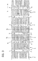
- the various segments of the stent 1 shown therein are connected to one another by pairs of bridges 3, 4 (actually constituting integral parts of the stent wall, as will be explained further below, for example, with reference to Figure 3) the essential characteristic of which (this applies both to the stent of Figures 1 and 2 and to the stent of Figures 7 and 8) is to articulate the segments 2 connected respectively thereby in an alternating sequence about mutually perpendicular flexing or bending axes.
- the longitudinal flexibility of the stent 1 which is necessary to facilitate its location at the implantation site, is demanded essentially of the bridges 3, 4, whereas the structural strength and hence the support for the lumen is demanded of the actual structures of the segments 2; all of this is achieved with a capability to optimize the desired characteristics by precise adaptation of the sections of the various component elements.
- the arrangement of the bridges in a sequence (usually, but not necessarily, alternating), in combination with the fact that, as stated, the segments 2 are quite short, enables a bend to be formed easily, in practice, at any point along the length of the stent 1 in any direction in space, and with very small radii of curvature.
- the bridges 4 which are also arranged at 180° to one another in a plane perpendicular to that of the bridges 3, allow the stent 1 to bend locally about a second axis y transverse the longitudinal axis z and, in the embodiment shown, perpendicular to the above-mentioned axis x.
- the segments 2 are quite short, the aforesaid axes x and y are arranged in close proximity to one another in alternating sequence along the length of the stent 1, however many segments 2 there may be.
- alternating sequence described above that is: axis x, axis y, axis x, axis y may, at least in principle, be replaced by a different sequence, for example, axis x, axis x, axis y, axis y, axis x, axis x, etc.
- Provision for a capability to bend about the axis x in two adjacent segments 2 followed by a capability to bend about the axis y repeated for two adjacent segments 2, as in the latter example mentioned may, in fact, be advantageous in applications in which an ability to achieve very small radii of curvature is to be given preference.
- the stent 2 can thus also be bent in the location of each connection between adjacent segments 2 about a generic axis d defined by an equation such as equation (I) introduced above.
- each segment 2 is constituted, in the embodiments shown, by a set of approximately sinusoidal loops of substantially uniform size (measured circumferentially relative to the element 2) which is doubled in the region of the loops from which the bridges 3, 4 extend, in the manner explained further below.
- each segment 2 is constituted by a sequence of loops, each loop (approximately comparable to half of a sinusoidal wave) defining a respective concave portion 5 the concave side of which faces towards the median plane X2, and which is connected to two approximately straight arms 6.
- the radial expansion of the stent 1 takes place substantially as a result of an opening-out of the aforementioned loops; by way of indication, with reference to the development in a plane of Figure 3, the radial expansion of the stent corresponds to a stretching of the development in a plane shown in Figure 3 in the sense of an increase in height and hence a vertical expansion of Figure 3.
- this radial expansion corresponds to an opening-out of the concave portions 5, whereas the lateral arms 6 of each loop remain substantially straight.
- the localization of the plastic deformation of the stent 2 in the concave portions of the loops 5 may be favoured (as will be explained further below with reference to Figure 4) by means of the cross-sections and/or the cross-sectional areas of the portions of each loop.
- the radial expansion (vertical stretching of the development in a plane of Figure 3) affects essentially the concave portions 5 of the loops of the elements 2 and in no way affects the bridges 3, 4 which extend longitudinally (axis z).
- connection to the relative segments 2 is formed in the region of the concave (or inside) portion of a respective loop, it can easily be appreciated that the radial expansion of the segments 2 is accompanied, so to speak, by a thrust exerted on the bridges 3, 4 (and on the respective spine portions 30). This thrust corresponds, so to speak, to an expulsion of the bridges or of the spine portions in question from the corresponding segment 2.
- the bridges 4' indicated above are extremely short (it will be remembered, by way of reference, that the axial length of the segments 2 may be of the order of 2 mm). Even during radial expansion, the concave portions (and consequently the convex portions) of all of the loops of each segment in any case retain their alignment with a plane parallel to the median plane X2 at each end of each segment 2. This alignment is thus also retained by the concave or convex portions connected between two adjacent segments 2 by the same bridge 3, the length of which is not changed during the radial expansion.
- each of the segments 2 constitutes a section which is intended to contract longitudinally as a result of the radial expansion.
- a corresponding connection of bridges 3, 4 is therefore provided in each of these segments according to the criteria described above.
- each set of two segments 2 interconnected by respective bridges 3 constitutes, precisely for the reasons described above, a section of stent which does not contract substantially longitudinally during radial expansion.
- the connection between these sections can take place by means of bridges such as those which are indicated 4' and shown in broken outline in the drawing and which are not connected to a concave (or inside) loop portion.
- Figure 4 shows how a stent wall structure having the geometry described with reference to Figure 3 can also be formed from one or more pieces of wire bent so as to form a set of loops which is substantially similar to that shown in Figure 3, and in which the bridges 3 and 4 are constituted by wire portions which are coupled (that is, placed side by side parallel to one another) and connected, for example, by welding or other joining methods (for example, brazing, gluing, crimping, etc.).
- a wire enables different cross-sections and/or cross-sectional areas to be attributed (for example, by a mechanical operation to shape the wire) to the concave portions 5 of the loops and to the straight arms 6 which extend therefrom.
- the cross-section of Figure 5 is in fact the cross section of a concave portion taken in its tip portion, whereas the cross-section of Figure 6 corresponds to the connection region of two straight arms extending generally longitudinally relative to the stent (axis z).
- the wire constituting the stent wall may retain a round cross-section, but in the straight portions 6 may adopt a cross-section which is generally flattened in the plane of the wall (and hence along the imaginary cylindrical envelope) of the stent 1.
- the straight portions 6 are intrinsically more resistant to bending in the plane in which they are generally flattened so that the a force opening out the two arms 6 connected to a common concave portion 5 brings about a deformation of the loop in the concave portion 5.
- the arms 6 are opened out, they retain a generally straight shape; in this connection, it will be noted that the arms which are coupled to form the bridges 3 and 4 nevertheless retain a straight orientation along the longitudinal axis z of the stent 1.
- the arms 6 expose a wider surface to the wall of the lumen supported by the stent in its radially expanded condition.
- the wall of the lumen is therefore subjected to a distributed load preventing the formation of concentrated stress regions.
- the dimensions of the wire can be optimized in the concave portions 5 in order to achieve optimal characteristics of plastic deformability when the stent is expanded radially and, at the same time, resistance to subsequent stresses which may tend to close up the stent 1.
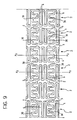
- the wall structure of Figure 9 differs from that shown in Figures 3 and 4 essentially in that the bridges which interconnect the various segments 2 are constituted by the two spines 30 extending with a generally sinusoidal shape along two diametrally opposed generatrices of the structure of the stent 1.
- a structure with spines of the type described can also implement an equation such as equation (I) given above, for the purposes of the longitudinal bending of the stent 1.
- equation (I) the difference in comparison with the embodiment shown in Figures 1 to 4 lies in the fact that, in this first solution, the axes x and y in fact correspond to the axes about which the bending of the pairs of bridges 3, 4 can take place.
- each section of the spine 30 extending to connect two adjacent segments 2 can express two possibilities for relative orientation between the two segments 2 connected, that is:
- the generally sinusoidal shape of the two spines 30 enables the longitudinal extensibility of the spines to be utilized for bending purposes without giving rise to stresses which are oriented tangentially relative to the wall of the stent and hence risk giving rise to undesired twisting. It will, in any case, be appreciated that the length of the stent of Figures 7 to 9 (that is, its extent along the axis z) can change entirely independently of the radial expansion of the segments 2.
- the overall shape of the spines 30 is sinusoidal and, even where they are connected to concave portions of respective loops (see in particular the portion of the spine 30 which is shown in the lower portion of Figure 9 connecting the two elements 2 of which the median planes X2 are indicated) the connection with these concave portions 5 does not change the general sinusoidal shape of the spine in question.
- the spine 30 is connected to the outer edge of the outside of the concave portion 5 on one side or wall thereof and continues from the inside of the concave portion, from the opposite side or wall.
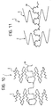
- the solution described provides for the entire body 1 of the stent, or at least part of it, to be constituted by a substantially reticular structure, the branches of which (in the embodiment shown, the annular walls of the segments 2 and the two spines 30) define geometrical figures which can be identified as fractals.
- fractal coined by the mathematician B. Mandelbrot in 1975, indicates in general a geometrical figure which has internal symmetries to whatever scale it is enlarged, and which is produced as a limit configuration of a succession of fragmentary curves from each of which the next is obtained on the basis of an assigned rule, for example, by replacing each side with a predetermined fragmentary, so-called generative or generator line.
- Figure 10 shows, by way of example, the use of higher-order fractals to produce segments 2
- Figure 11 shows, by way of example, the use of higher-order fractals to produce the spine or spines 30.
- the solutions shown by way of example may be combined, in the sense that the higher-order fractals may be used both for the segments 2 and for the spines 30.
- fractal geometry has been found advantageous since it enables the performance and/or the mechanical characteristics of the various portions of the wall of the stent 1 to be optimized with regard to the specific stresses to which it has to respond in use.
Landscapes
- Health & Medical Sciences (AREA)
- Engineering & Computer Science (AREA)
- Biomedical Technology (AREA)
- Heart & Thoracic Surgery (AREA)
- Life Sciences & Earth Sciences (AREA)
- Cardiology (AREA)
- Oral & Maxillofacial Surgery (AREA)
- Transplantation (AREA)
- Veterinary Medicine (AREA)
- Vascular Medicine (AREA)
- Public Health (AREA)
- Animal Behavior & Ethology (AREA)
- General Health & Medical Sciences (AREA)
- Optics & Photonics (AREA)
- Physics & Mathematics (AREA)
- Prostheses (AREA)
- Media Introduction/Drainage Providing Device (AREA)
- Materials For Medical Uses (AREA)
- Acyclic And Carbocyclic Compounds In Medicinal Compositions (AREA)
Claims (5)
- Endoprothèse vasculaire pour angioplastie comprenant un corps (1) qui a généralement une enveloppe tubulaire et qui peut se déployer en fonctionnement depuis un état de contraction radiale vers un état d'extension radiale dans laquelle l'endoprothèse vasculaire soutient la paroi d'une lumière, dans laquelle le corps de l'endoprothèse vasculaire est constitué par un ensemble de segments successifs, extensibles suivant une direction radiale et généralement annulaires (2), et la paroi du corps comprend des bras (6) pour soutenir la lumière, ainsi que des régions (5) qui sont sélectivement déformables pendant le déploiement de l'endoprothèse vasculaire, dans laquelle la paroi des segments (2) dudit corps (1) comprend un ensemble de boucles ayant chacune une partie concave (5) formant l'une desdites régions sélectivement déformables à partir de laquelle s'étendent des bras latéraux (6), caractérisée en ce que les bras (6) ont une forme qui est généralement aplatie dans le plan général de la paroi du corps de telle sorte que les faces externes des bras (6) définissent de larges surfaces de soutien respectives pour la paroi de la lumière, et en ce que la partie concave (5) a une coupe transversale essentiellement circulaire, de telle sorte que pendant le déploiement radial de l'endoprothèse vasculaire, la partie concave (5) et les bras (6) adoptent différents comportements.
- Endoprothèse vasculaire selon la revendication 1, caractérisée en ce que la paroi du corps (1) est constituée essentiellement par au moins un élément en fil métallique recourbé.
- Endoprothèse vasculaire selon la revendication 2, caractérisée en ce que la paroi comprend des parties adjacentes de fil métallique fermement reliées les unes aux autres.
- Endoprothèse vasculaire selon la revendication 3, caractérisée en ce que les parties adjacentes de fil métallique sont reliées les unes aux autres par soudage, brasage, collage, sertissage ou une combinaison de ceux-ci.
- Endoprothèse vasculaire selon la revendication 1, caractérisée en ce que lesdits segments (2) sont reliés entre eux par des éléments de ponts (30) s'étirant essentiellement dans la direction de l'axe longitudinal (z) de l'endoprothèse vasculaire de telle sorte que les éléments de ponts (30) ne sont sensiblement pas affectés par le déploiement radial des segments (2) et les éléments de ponts (30) sont généralement déformables dans la direction de l'axe longitudinal (z) de telle sorte que la longueur de l'endoprothèse vasculaire (1) le long de l'axe (z) peut changer sensiblement indépendamment du déploiement radial.
Priority Applications (1)
| Application Number | Priority Date | Filing Date | Title |
|---|---|---|---|
| EP03016995A EP1354569B1 (fr) | 1996-05-08 | 1997-05-06 | Un stent pour angioplastie |
Applications Claiming Priority (10)
| Application Number | Priority Date | Filing Date | Title |
|---|---|---|---|
| ITTO960373 | 1996-05-08 | ||
| IT96TO000377 IT1285092B1 (it) | 1996-05-08 | 1996-05-08 | Stent per angioplastica. |
| ITTO960374 IT1285089B1 (it) | 1996-05-08 | 1996-05-08 | Stent per angioplastica. |
| ITTO960374 | 1996-05-08 | ||
| IT96TO000373 IT1285088B1 (it) | 1996-05-08 | 1996-05-08 | Stent per angioplastica. |
| ITTO960375 | 1996-05-08 | ||
| ITTO960376 IT1285091B1 (it) | 1996-05-08 | 1996-05-08 | Stent per angioplastica. |
| ITTO960377 | 1996-05-08 | ||
| ITTO960375 IT1285090B1 (it) | 1996-05-08 | 1996-05-08 | Stent per angioplastica. |
| ITTO960376 | 1996-05-08 |
Related Child Applications (1)
| Application Number | Title | Priority Date | Filing Date |
|---|---|---|---|
| EP03016995A Division EP1354569B1 (fr) | 1996-05-08 | 1997-05-06 | Un stent pour angioplastie |
Publications (2)
| Publication Number | Publication Date |
|---|---|
| EP0806190A1 EP0806190A1 (fr) | 1997-11-12 |
| EP0806190B1 true EP0806190B1 (fr) | 2004-01-02 |
Family
ID=27517904
Family Applications (2)
| Application Number | Title | Priority Date | Filing Date |
|---|---|---|---|
| EP03016995A Expired - Lifetime EP1354569B1 (fr) | 1996-05-08 | 1997-05-06 | Un stent pour angioplastie |
| EP97107423A Expired - Lifetime EP0806190B1 (fr) | 1996-05-08 | 1997-05-06 | Un stent pour angioplastie |
Family Applications Before (1)
| Application Number | Title | Priority Date | Filing Date |
|---|---|---|---|
| EP03016995A Expired - Lifetime EP1354569B1 (fr) | 1996-05-08 | 1997-05-06 | Un stent pour angioplastie |
Country Status (5)
| Country | Link |
|---|---|
| EP (2) | EP1354569B1 (fr) |
| AT (2) | ATE257002T1 (fr) |
| DE (2) | DE69738786D1 (fr) |
| DK (1) | DK0806190T3 (fr) |
| ES (1) | ES2212013T3 (fr) |
Cited By (2)
| Publication number | Priority date | Publication date | Assignee | Title |
|---|---|---|---|---|
| US6846323B2 (en) | 2003-05-15 | 2005-01-25 | Advanced Cardiovascular Systems, Inc. | Intravascular stent |
| US8449597B2 (en) | 1995-03-01 | 2013-05-28 | Boston Scientific Scimed, Inc. | Longitudinally flexible expandable stent |
Families Citing this family (82)
| Publication number | Priority date | Publication date | Assignee | Title |
|---|---|---|---|---|
| IT1289815B1 (it) | 1996-12-30 | 1998-10-16 | Sorin Biomedica Cardio Spa | Stent per angioplastica e relativo procedimento di produzione |
| US20020133222A1 (en) * | 1997-03-05 | 2002-09-19 | Das Gladwin S. | Expandable stent having a plurality of interconnected expansion modules |
| US6451049B2 (en) | 1998-04-29 | 2002-09-17 | Sorin Biomedica Cardio, S.P.A. | Stents for angioplasty |
| FR2764794B1 (fr) * | 1997-06-20 | 1999-11-12 | Nycomed Lab Sa | Dispositif tubulaire expanse a epaisseur variable |
| US6309414B1 (en) | 1997-11-04 | 2001-10-30 | Sorin Biomedica Cardio S.P.A. | Angioplasty stents |
| US6342067B1 (en) * | 1998-01-09 | 2002-01-29 | Nitinol Development Corporation | Intravascular stent having curved bridges for connecting adjacent hoops |
| US6019789A (en) | 1998-04-01 | 2000-02-01 | Quanam Medical Corporation | Expandable unit cell and intraluminal stent |
| US6264687B1 (en) | 1998-04-20 | 2001-07-24 | Cordis Corporation | Multi-laminate stent having superelastic articulated sections |
| ES2221413T3 (es) * | 1998-07-17 | 2004-12-16 | B. Braun Melsungen Ag | Stent expandible. |
| FR2781143B1 (fr) * | 1998-07-17 | 2000-11-10 | Braun Celsa Sa | Support expansible a meandres pour un conduit anatomique,en particulier, un vaisseau sanguin |
| US6254564B1 (en) | 1998-09-10 | 2001-07-03 | Percardia, Inc. | Left ventricular conduit with blood vessel graft |
| WO2000042945A1 (fr) * | 1999-01-22 | 2000-07-27 | Al Saadon Khalid | Extenseur medical tubulaire expansible pour application endovasculaire |
| EP1152710A1 (fr) * | 1999-01-22 | 2001-11-14 | Khalid Al-Saadon | Extenseurs intravasculaires tubulaires expansibles |
| US6425855B2 (en) | 1999-04-06 | 2002-07-30 | Cordis Corporation | Method for making a multi-laminate stent having superelastic articulated sections |
| CA2376069A1 (fr) * | 1999-06-30 | 2001-01-04 | Advanced Cardiovascular Systems, Inc. | Stent a epaisseur variable, et son procede de fabrication |
| ES2243274T3 (es) * | 1999-07-02 | 2005-12-01 | Endotex Interventional Systems, Inc. | Stent flexible y estirable en forma de hoja. |
| IT1307263B1 (it) | 1999-08-05 | 2001-10-30 | Sorin Biomedica Cardio Spa | Stent per angioplastica con azione antagonista della restenosi,relativo corredo e componenti. |
| US6540774B1 (en) | 1999-08-31 | 2003-04-01 | Advanced Cardiovascular Systems, Inc. | Stent design with end rings having enhanced strength and radiopacity |
| DE69934990T2 (de) | 1999-11-23 | 2007-11-15 | Sorin Biomedica Cardio S.R.L., Saluggia | Verfahren zur Übertragung radioaktiver Stoffe auf Stents in der Angioplastie und Bausatz |
| DE10010073B4 (de) | 2000-02-28 | 2005-12-22 | Fraunhofer-Gesellschaft zur Förderung der angewandten Forschung e.V. | Verankerung für implantierbare Herzklappenprothesen |
| DE10010074B4 (de) | 2000-02-28 | 2005-04-14 | Fraunhofer-Gesellschaft zur Förderung der angewandten Forschung e.V. | Vorrichtung zur Befestigung und Verankerung von Herzklappenprothesen |
| US6616689B1 (en) * | 2000-05-03 | 2003-09-09 | Advanced Cardiovascular Systems, Inc. | Intravascular stent |
| US6652579B1 (en) | 2000-06-22 | 2003-11-25 | Advanced Cardiovascular Systems, Inc. | Radiopaque stent |
| US6547818B1 (en) * | 2000-10-20 | 2003-04-15 | Endotex Interventional Systems, Inc. | Selectively thinned coiled-sheet stents and methods for making them |
| EP1212986A1 (fr) | 2000-12-08 | 2002-06-12 | SORIN BIOMEDICA CARDIO S.p.A. | Stent pour angioplastie et son méthode de manufacture |
| PT2311411E (pt) † | 2000-12-11 | 2015-11-17 | Orbusneich Medical Inc | Endoprótese com elementos helicoidais |
| US6929660B1 (en) * | 2000-12-22 | 2005-08-16 | Advanced Cardiovascular Systems, Inc. | Intravascular stent |
| JP4815057B2 (ja) * | 2001-02-13 | 2011-11-16 | 株式会社カネカ | ステント |
| CN1289160C (zh) * | 2001-02-01 | 2006-12-13 | 钟渊化学工业株式会社 | 扩张器 |
| JP5011604B2 (ja) * | 2001-02-01 | 2012-08-29 | 株式会社カネカ | ステント |
| JP4857470B2 (ja) * | 2001-02-01 | 2012-01-18 | 株式会社カネカ | ステント |
| US7201940B1 (en) | 2001-06-12 | 2007-04-10 | Advanced Cardiovascular Systems, Inc. | Method and apparatus for thermal spray processing of medical devices |
| US6749629B1 (en) | 2001-06-27 | 2004-06-15 | Advanced Cardiovascular Systems, Inc. | Stent pattern with figure-eights |
| US6605110B2 (en) | 2001-06-29 | 2003-08-12 | Advanced Cardiovascular Systems, Inc. | Stent with enhanced bendability and flexibility |
| ATE330564T1 (de) | 2001-07-20 | 2006-07-15 | Sorin Biomedica Cardio Srl | Stent |
| FR2828263B1 (fr) | 2001-08-03 | 2007-05-11 | Philipp Bonhoeffer | Dispositif d'implantation d'un implant et procede d'implantation du dispositif |
| SG108867A1 (en) * | 2001-09-06 | 2005-02-28 | Medinol Ltd | Self articulating stent |
| DE10144430A1 (de) * | 2001-09-06 | 2003-03-27 | Biotronik Mess & Therapieg | Stent mit variablem Stegquerschnitt |
| EP1310242A1 (fr) | 2001-11-13 | 2003-05-14 | SORIN BIOMEDICA CARDIO S.p.A. | Support et kit pour l'administration endoluminale des agents actifs |
| US7537607B2 (en) | 2001-12-21 | 2009-05-26 | Boston Scientific Scimed, Inc. | Stent geometry for improved flexibility |
| US6656220B1 (en) | 2002-06-17 | 2003-12-02 | Advanced Cardiovascular Systems, Inc. | Intravascular stent |
| US20040054398A1 (en) * | 2002-09-13 | 2004-03-18 | Cully Edward H. | Stent device with multiple helix construction |
| US20040102831A1 (en) * | 2002-11-22 | 2004-05-27 | Murray Robert J. | Stent having tapered edges |
| ATE538820T1 (de) | 2003-02-21 | 2012-01-15 | Sorin Biomedica Cardio Srl | Verfahren zur herstellung eines stents und entsprechender stent |
| JP4546481B2 (ja) * | 2003-09-30 | 2010-09-15 | アルヴィオラス,インコーポレイテッド | 取外し可能なステント |
| ITTO20040056A1 (it) | 2004-02-05 | 2004-05-05 | Sorin Biomedica Cardio Spa | Stent per l'erogazione endoliminale di principi o agenti attivi |
| US8961583B2 (en) | 2004-09-08 | 2015-02-24 | Cordis Corporation | Optimized flex link for expandable stent |
| DE102005003632A1 (de) | 2005-01-20 | 2006-08-17 | Fraunhofer-Gesellschaft zur Förderung der angewandten Forschung e.V. | Katheter für die transvaskuläre Implantation von Herzklappenprothesen |
| US8628565B2 (en) | 2005-04-13 | 2014-01-14 | Abbott Cardiovascular Systems Inc. | Intravascular stent |
| DE102005051849B4 (de) | 2005-10-28 | 2010-01-21 | JenaValve Technology Inc., Wilmington | Vorrichtung zur Implantation und Befestigung von Herzklappenprothesen |
| DE102005052628B4 (de) | 2005-11-04 | 2014-06-05 | Jenavalve Technology Inc. | Selbstexpandierendes, flexibles Drahtgeflecht mit integrierter Klappenprothese für den transvaskulären Herzklappenersatz und ein System mit einer solchen Vorrichtung und einem Einführkatheter |
| US20070213813A1 (en) | 2005-12-22 | 2007-09-13 | Symetis Sa | Stent-valves for valve replacement and associated methods and systems for surgery |
| US9138315B2 (en) | 2007-04-13 | 2015-09-22 | Jenavalve Technology Gmbh | Medical device for treating a heart valve insufficiency or stenosis |
| US7896915B2 (en) | 2007-04-13 | 2011-03-01 | Jenavalve Technology, Inc. | Medical device for treating a heart valve insufficiency |
| EP2659861B1 (fr) | 2007-05-15 | 2019-03-13 | JenaValve Technology, Inc. | Poignée permettant de manipuler une pointe de cathéter, cathéter et système d'insertion médical permettant d'insérer une endoprothèse valvulaire cardiaque auto-dilatable |
| US9044318B2 (en) | 2008-02-26 | 2015-06-02 | Jenavalve Technology Gmbh | Stent for the positioning and anchoring of a valvular prosthesis |
| US8465540B2 (en) | 2008-02-26 | 2013-06-18 | Jenavalve Technology, Inc. | Stent for the positioning and anchoring of a valvular prosthesis |
| WO2011104269A1 (fr) | 2008-02-26 | 2011-09-01 | Jenavalve Technology Inc. | Stent pour le positionnement et l'ancrage d'une prothèse valvulaire dans un site d'implantation dans le cœur d'un patient |
| US8317858B2 (en) | 2008-02-26 | 2012-11-27 | Jenavalve Technology, Inc. | Stent for the positioning and anchoring of a valvular prosthesis in an implantation site in the heart of a patient |
| US9168130B2 (en) | 2008-02-26 | 2015-10-27 | Jenavalve Technology Gmbh | Stent for the positioning and anchoring of a valvular prosthesis in an implantation site in the heart of a patient |
| US8398704B2 (en) | 2008-02-26 | 2013-03-19 | Jenavalve Technology, Inc. | Stent for the positioning and anchoring of a valvular prosthesis in an implantation site in the heart of a patient |
| US20100292779A1 (en) | 2009-05-15 | 2010-11-18 | Helmut Straubinger | Device for compressing a stent and a system as well as a method for loading a stent into a medical delivery system |
| US10856978B2 (en) | 2010-05-20 | 2020-12-08 | Jenavalve Technology, Inc. | Catheter system |
| US11278406B2 (en) | 2010-05-20 | 2022-03-22 | Jenavalve Technology, Inc. | Catheter system for introducing an expandable heart valve stent into the body of a patient, insertion system with a catheter system and medical device for treatment of a heart valve defect |
| WO2011147849A1 (fr) | 2010-05-25 | 2011-12-01 | Jenavalve Technology Inc. | Valvule prothétique et endoprothèse mise en place par cathétérisme comprenant une valvule prothétique et un stent |
| EP2572681A1 (fr) * | 2011-09-23 | 2013-03-27 | Biotronik AG | Implant et son procédé de fabrication |
| CN104159543B (zh) | 2011-10-21 | 2016-10-12 | 耶拿阀门科技公司 | 用于将可扩张心脏瓣膜支架引入患者体内的导管系统 |
| JP6227632B2 (ja) | 2012-05-16 | 2017-11-08 | イェーナヴァルヴ テクノロジー ゲゼルシャフト ミット ベシュレンクテル ハフツング | 拡張可能心臓代用弁を導入するためのカテーテル送達システムおよび心臓弁欠陥の治療のための医療デバイス |
| US9913740B2 (en) * | 2012-10-25 | 2018-03-13 | W. L. Gore & Associates, Inc. | Stent with varying cross-section |
| WO2015028209A1 (fr) | 2013-08-30 | 2015-03-05 | Jenavalve Technology Gmbh | Cadre radialement repliable pour valvule prothétique et procédé de fabrication dudit cadre |
| US10307273B2 (en) | 2015-03-03 | 2019-06-04 | Boston Scientific Scimed, Inc. | Stent with anti-migration features |
| EP3270825B1 (fr) | 2015-03-20 | 2020-04-22 | JenaValve Technology, Inc. | Système de pose de prothèse de valvule cardiaque |
| EP3288495B1 (fr) | 2015-05-01 | 2019-09-25 | JenaValve Technology, Inc. | Dispositif à débit réduit de stimulateur cardiaque lors d'un remplacement de valvules cardiaques |
| WO2017195125A1 (fr) | 2016-05-13 | 2017-11-16 | Jenavalve Technology, Inc. | Système d'implantation de prothèse de valve cardiaque et procédé pour la pose d'une prothèse de valve cardiaque avec une gaine d'introduction et système de chargement |
| US11197754B2 (en) | 2017-01-27 | 2021-12-14 | Jenavalve Technology, Inc. | Heart valve mimicry |
| EP3833210A1 (fr) | 2018-08-10 | 2021-06-16 | Louis Vuitton Malletier | Procédé pour réaliser une coque de bagage rigide, coque de bagage et bagage |
| FR3084822B1 (fr) | 2018-08-10 | 2022-01-07 | Vuitton Louis Sa | Procede pour realiser un bagage, en particulier un sac de voyage souple ou semi-rigide |
| EP3911246B1 (fr) | 2019-01-18 | 2025-11-05 | W. L. Gore & Associates, Inc. | Dispositifs médicaux bioabsorbables |
| IT201900003579A1 (it) | 2019-03-12 | 2020-09-12 | Alvimedica Tibbi Ueruenler Sanayi Ve Dis Ticaret A S | Stent per ostio coronarico |
| EP4125738A1 (fr) * | 2020-03-24 | 2023-02-08 | The Foundry, LLC | Dispositifs déployables et systèmes et procédés associés |
| WO2022174856A1 (fr) * | 2021-02-20 | 2022-08-25 | Christian-Albrechts-Universität Zu Kiel | Structure de bande auxétique ou structure de champ, et utilisation |
| US12171658B2 (en) | 2022-11-09 | 2024-12-24 | Jenavalve Technology, Inc. | Catheter system for sequential deployment of an expandable implant |
Family Cites Families (12)
| Publication number | Priority date | Publication date | Assignee | Title |
|---|---|---|---|---|
| US4503569A (en) | 1983-03-03 | 1985-03-12 | Dotter Charles T | Transluminally placed expandable graft prosthesis |
| EP0210466A3 (fr) | 1985-08-01 | 1991-07-10 | International Business Machines Corporation | Procédé de transfert de groupes VSAM en gardant des indices remplaçants dans le groupe |
| US4733665C2 (en) | 1985-11-07 | 2002-01-29 | Expandable Grafts Partnership | Expandable intraluminal graft and method and apparatus for implanting an expandable intraluminal graft |
| EP0556940A1 (fr) | 1986-02-24 | 1993-08-25 | Robert E. Fischell | Stent intravasculaire |
| US4800882A (en) | 1987-03-13 | 1989-01-31 | Cook Incorporated | Endovascular stent and delivery system |
| US4907336A (en) | 1987-03-13 | 1990-03-13 | Cook Incorporated | Method of making an endovascular stent and delivery system |
| US4886062A (en) | 1987-10-19 | 1989-12-12 | Medtronic, Inc. | Intravascular radially expandable stent and method of implant |
| US4830003A (en) | 1988-06-17 | 1989-05-16 | Wolff Rodney G | Compressive stent and delivery system |
| US4856516A (en) | 1989-01-09 | 1989-08-15 | Cordis Corporation | Endovascular stent apparatus and method |
| CA2380683C (fr) * | 1991-10-28 | 2006-08-08 | Advanced Cardiovascular Systems, Inc. | Empreintes extensibles et leur methode de fabrication |
| US5449373A (en) * | 1994-03-17 | 1995-09-12 | Medinol Ltd. | Articulated stent |
| US5733303A (en) * | 1994-03-17 | 1998-03-31 | Medinol Ltd. | Flexible expandable stent |
-
1997
- 1997-05-06 ES ES97107423T patent/ES2212013T3/es not_active Expired - Lifetime
- 1997-05-06 EP EP03016995A patent/EP1354569B1/fr not_active Expired - Lifetime
- 1997-05-06 AT AT97107423T patent/ATE257002T1/de not_active IP Right Cessation
- 1997-05-06 AT AT03016995T patent/ATE398425T1/de not_active IP Right Cessation
- 1997-05-06 DE DE69738786T patent/DE69738786D1/de not_active Expired - Lifetime
- 1997-05-06 EP EP97107423A patent/EP0806190B1/fr not_active Expired - Lifetime
- 1997-05-06 DE DE69727004T patent/DE69727004T2/de not_active Expired - Lifetime
- 1997-05-06 DK DK97107423T patent/DK0806190T3/da active
Cited By (3)
| Publication number | Priority date | Publication date | Assignee | Title |
|---|---|---|---|---|
| US8449597B2 (en) | 1995-03-01 | 2013-05-28 | Boston Scientific Scimed, Inc. | Longitudinally flexible expandable stent |
| US8728147B2 (en) | 1995-03-01 | 2014-05-20 | Boston Scientific Limited | Longitudinally flexible expandable stent |
| US6846323B2 (en) | 2003-05-15 | 2005-01-25 | Advanced Cardiovascular Systems, Inc. | Intravascular stent |
Also Published As
| Publication number | Publication date |
|---|---|
| DE69727004D1 (de) | 2004-02-05 |
| ATE257002T1 (de) | 2004-01-15 |
| DE69738786D1 (de) | 2008-07-31 |
| EP1354569B1 (fr) | 2008-06-18 |
| DE69727004T2 (de) | 2004-11-25 |
| EP1354569A1 (fr) | 2003-10-22 |
| DK0806190T3 (da) | 2004-05-03 |
| ES2212013T3 (es) | 2004-07-16 |
| EP0806190A1 (fr) | 1997-11-12 |
| ATE398425T1 (de) | 2008-07-15 |
Similar Documents
| Publication | Publication Date | Title |
|---|---|---|
| EP0806190B1 (fr) | Un stent pour angioplastie | |
| US8439965B2 (en) | Angioplasty stents | |
| US8728147B2 (en) | Longitudinally flexible expandable stent | |
| EP0875215B1 (fr) | Stent pour Angioplastie | |
| CA2316286C (fr) | Prothese endovasculaire extensible et longitudinalement flexible | |
| EP1970033B1 (fr) | Extenseur dilatable à flexibilité longitudinale améliorée | |
| EP1163889A2 (fr) | Extenseur dilatable a flexibilite longitudinale amelioree | |
| ITTO960376A1 (it) | Stent per angioplastica. | |
| ITTO960374A1 (it) | Stent per angioplastica. | |
| ITTO960375A1 (it) | Stent per angioplastica. |
Legal Events
| Date | Code | Title | Description |
|---|---|---|---|
| PUAI | Public reference made under article 153(3) epc to a published international application that has entered the european phase |
Free format text: ORIGINAL CODE: 0009012 |
|
| AK | Designated contracting states |
Kind code of ref document: A1 Designated state(s): AT BE CH DE DK ES FR GB IE IT LI NL SE |
|
| 17P | Request for examination filed |
Effective date: 19980418 |
|
| 17Q | First examination report despatched |
Effective date: 20020912 |
|
| GRAH | Despatch of communication of intention to grant a patent |
Free format text: ORIGINAL CODE: EPIDOS IGRA |
|
| GRAS | Grant fee paid |
Free format text: ORIGINAL CODE: EPIDOSNIGR3 |
|
| RIN1 | Information on inventor provided before grant (corrected) |
Inventor name: CERISE, OSVALDO Inventor name: VALLANA, FRANCO Inventor name: GASCHINO, PAOLO Inventor name: ROLANDO, GIOVANNI |
|
| GRAA | (expected) grant |
Free format text: ORIGINAL CODE: 0009210 |
|
| AK | Designated contracting states |
Kind code of ref document: B1 Designated state(s): AT BE CH DE DK ES FR GB IE IT LI NL SE |
|
| PG25 | Lapsed in a contracting state [announced via postgrant information from national office to epo] |
Ref country code: BE Free format text: LAPSE BECAUSE OF FAILURE TO SUBMIT A TRANSLATION OF THE DESCRIPTION OR TO PAY THE FEE WITHIN THE PRESCRIBED TIME-LIMIT Effective date: 20040102 Ref country code: AT Free format text: LAPSE BECAUSE OF FAILURE TO SUBMIT A TRANSLATION OF THE DESCRIPTION OR TO PAY THE FEE WITHIN THE PRESCRIBED TIME-LIMIT Effective date: 20040102 |
|
| REG | Reference to a national code |
Ref country code: GB Ref legal event code: FG4D |
|
| REG | Reference to a national code |
Ref country code: CH Ref legal event code: NV Representative=s name: ISLER & PEDRAZZINI AG Ref country code: CH Ref legal event code: EP |
|
| REG | Reference to a national code |
Ref country code: IE Ref legal event code: FG4D |
|
| REG | Reference to a national code |
Ref country code: SE Ref legal event code: TRGR |
|
| REF | Corresponds to: |
Ref document number: 69727004 Country of ref document: DE Date of ref document: 20040205 Kind code of ref document: P |
|
| REG | Reference to a national code |
Ref country code: DK Ref legal event code: T3 |
|
| REG | Reference to a national code |
Ref country code: ES Ref legal event code: FG2A Ref document number: 2212013 Country of ref document: ES Kind code of ref document: T3 |
|
| ET | Fr: translation filed | ||
| PLBE | No opposition filed within time limit |
Free format text: ORIGINAL CODE: 0009261 |
|
| STAA | Information on the status of an ep patent application or granted ep patent |
Free format text: STATUS: NO OPPOSITION FILED WITHIN TIME LIMIT |
|
| RAP2 | Party data changed (patent owner data changed or rights of a patent transferred) |
Owner name: SORIN BIOMEDICA CARDIO S.R.L. |
|
| 26N | No opposition filed |
Effective date: 20041005 |
|
| NLT2 | Nl: modifications (of names), taken from the european patent patent bulletin |
Owner name: SORIN BIOMEDICA CARDIO S.R.L. |
|
| REG | Reference to a national code |
Ref country code: CH Ref legal event code: PCAR Free format text: ISLER & PEDRAZZINI AG;POSTFACH 1772;8027 ZUERICH (CH) |
|
| PGFP | Annual fee paid to national office [announced via postgrant information from national office to epo] |
Ref country code: NL Payment date: 20120515 Year of fee payment: 16 Ref country code: DK Payment date: 20120510 Year of fee payment: 16 |
|
| PGFP | Annual fee paid to national office [announced via postgrant information from national office to epo] |
Ref country code: SE Payment date: 20120511 Year of fee payment: 16 |
|
| REG | Reference to a national code |
Ref country code: DE Ref legal event code: R082 Ref document number: 69727004 Country of ref document: DE Representative=s name: PAUL & ALBRECHT PATENTANWALTSSOZIETAET, DE |
|
| REG | Reference to a national code |
Ref country code: CH Ref legal event code: PUE Owner name: CID S.P.A., IT Free format text: FORMER OWNER: SORIN BIOMEDICA CARDIO S.P.A., IT |
|
| REG | Reference to a national code |
Ref country code: DE Ref legal event code: R082 Ref document number: 69727004 Country of ref document: DE Representative=s name: PAUL & ALBRECHT PATENTANWALTSSOZIETAET, DE Effective date: 20130107 Ref country code: DE Ref legal event code: R081 Ref document number: 69727004 Country of ref document: DE Owner name: CID S.P.A., IT Free format text: FORMER OWNER: SORIN BIOMEDICA CARDIO S.P.A., SALUGGIA, VERCELLI, IT Effective date: 20130107 Ref country code: DE Ref legal event code: R081 Ref document number: 69727004 Country of ref document: DE Owner name: CID S.P.A., IT Free format text: FORMER OWNER: SORIN BIOMEDICA CARDIO S.P.A., SALUGGIA, IT Effective date: 20130107 |
|
| REG | Reference to a national code |
Ref country code: FR Ref legal event code: TP Owner name: CID S.P.A., IT Effective date: 20130506 Ref country code: FR Ref legal event code: CD Owner name: CID S.P.A., IT Effective date: 20130506 |
|
| REG | Reference to a national code |
Ref country code: GB Ref legal event code: 732E Free format text: REGISTERED BETWEEN 20130627 AND 20130703 |
|
| REG | Reference to a national code |
Ref country code: NL Ref legal event code: V1 Effective date: 20131201 |
|
| REG | Reference to a national code |
Ref country code: SE Ref legal event code: EUG |
|
| PG25 | Lapsed in a contracting state [announced via postgrant information from national office to epo] |
Ref country code: SE Free format text: LAPSE BECAUSE OF NON-PAYMENT OF DUE FEES Effective date: 20130507 |
|
| REG | Reference to a national code |
Ref country code: DK Ref legal event code: EBP Effective date: 20130531 |
|
| PG25 | Lapsed in a contracting state [announced via postgrant information from national office to epo] |
Ref country code: NL Free format text: LAPSE BECAUSE OF NON-PAYMENT OF DUE FEES Effective date: 20131201 |
|
| PG25 | Lapsed in a contracting state [announced via postgrant information from national office to epo] |
Ref country code: DK Free format text: LAPSE BECAUSE OF NON-PAYMENT OF DUE FEES Effective date: 20130531 |
|
| REG | Reference to a national code |
Ref country code: FR Ref legal event code: PLFP Year of fee payment: 20 |
|
| PGFP | Annual fee paid to national office [announced via postgrant information from national office to epo] |
Ref country code: ES Payment date: 20160412 Year of fee payment: 20 Ref country code: GB Payment date: 20160504 Year of fee payment: 20 Ref country code: DE Payment date: 20160504 Year of fee payment: 20 Ref country code: IE Payment date: 20160509 Year of fee payment: 20 Ref country code: CH Payment date: 20160511 Year of fee payment: 20 |
|
| PGFP | Annual fee paid to national office [announced via postgrant information from national office to epo] |
Ref country code: IT Payment date: 20160524 Year of fee payment: 20 Ref country code: FR Payment date: 20160412 Year of fee payment: 20 |
|
| REG | Reference to a national code |
Ref country code: DE Ref legal event code: R071 Ref document number: 69727004 Country of ref document: DE |
|
| REG | Reference to a national code |
Ref country code: CH Ref legal event code: PL |
|
| REG | Reference to a national code |
Ref country code: GB Ref legal event code: PE20 Expiry date: 20170505 |
|
| REG | Reference to a national code |
Ref country code: IE Ref legal event code: MK9A |
|
| PG25 | Lapsed in a contracting state [announced via postgrant information from national office to epo] |
Ref country code: GB Free format text: LAPSE BECAUSE OF EXPIRATION OF PROTECTION Effective date: 20170505 Ref country code: IE Free format text: LAPSE BECAUSE OF EXPIRATION OF PROTECTION Effective date: 20170506 |
|
| REG | Reference to a national code |
Ref country code: ES Ref legal event code: FD2A Effective date: 20180508 |
|
| PG25 | Lapsed in a contracting state [announced via postgrant information from national office to epo] |
Ref country code: ES Free format text: LAPSE BECAUSE OF EXPIRATION OF PROTECTION Effective date: 20170507 |