EP0806548A1 - Turbine d'un turbocompresseur à gaz d'échappement - Google Patents
Turbine d'un turbocompresseur à gaz d'échappement Download PDFInfo
- Publication number
- EP0806548A1 EP0806548A1 EP97810216A EP97810216A EP0806548A1 EP 0806548 A1 EP0806548 A1 EP 0806548A1 EP 97810216 A EP97810216 A EP 97810216A EP 97810216 A EP97810216 A EP 97810216A EP 0806548 A1 EP0806548 A1 EP 0806548A1
- Authority
- EP
- European Patent Office
- Prior art keywords
- ring
- housing
- gas inlet
- gas
- inlet housing
- Prior art date
- Legal status (The legal status is an assumption and is not a legal conclusion. Google has not performed a legal analysis and makes no representation as to the accuracy of the status listed.)
- Granted
Links
Images

Classifications
-
- F—MECHANICAL ENGINEERING; LIGHTING; HEATING; WEAPONS; BLASTING
- F02—COMBUSTION ENGINES; HOT-GAS OR COMBUSTION-PRODUCT ENGINE PLANTS
- F02C—GAS-TURBINE PLANTS; AIR INTAKES FOR JET-PROPULSION PLANTS; CONTROLLING FUEL SUPPLY IN AIR-BREATHING JET-PROPULSION PLANTS
- F02C6/00—Plural gas-turbine plants; Combinations of gas-turbine plants with other apparatus; Adaptations of gas-turbine plants for special use
- F02C6/04—Gas-turbine plants providing heated or pressurised working fluid for other apparatus, e.g. without mechanical power output
- F02C6/10—Gas-turbine plants providing heated or pressurised working fluid for other apparatus, e.g. without mechanical power output supplying working fluid to a user, e.g. a chemical process, which returns working fluid to a turbine of the plant
- F02C6/12—Turbochargers, i.e. plants for augmenting mechanical power output of internal-combustion piston engines by increase of charge pressure
-
- F—MECHANICAL ENGINEERING; LIGHTING; HEATING; WEAPONS; BLASTING
- F01—MACHINES OR ENGINES IN GENERAL; ENGINE PLANTS IN GENERAL; STEAM ENGINES
- F01D—NON-POSITIVE DISPLACEMENT MACHINES OR ENGINES, e.g. STEAM TURBINES
- F01D25/00—Component parts, details, or accessories, not provided for in, or of interest apart from, other groups
- F01D25/24—Casings; Casing parts, e.g. diaphragms, casing fastenings
- F01D25/246—Fastening of diaphragms or stator-rings
-
- F—MECHANICAL ENGINEERING; LIGHTING; HEATING; WEAPONS; BLASTING
- F01—MACHINES OR ENGINES IN GENERAL; ENGINE PLANTS IN GENERAL; STEAM ENGINES
- F01D—NON-POSITIVE DISPLACEMENT MACHINES OR ENGINES, e.g. STEAM TURBINES
- F01D9/00—Stators
- F01D9/02—Nozzles; Nozzle boxes; Stator blades; Guide conduits, e.g. individual nozzles
-
- F—MECHANICAL ENGINEERING; LIGHTING; HEATING; WEAPONS; BLASTING
- F02—COMBUSTION ENGINES; HOT-GAS OR COMBUSTION-PRODUCT ENGINE PLANTS
- F02B—INTERNAL-COMBUSTION PISTON ENGINES; COMBUSTION ENGINES IN GENERAL
- F02B39/00—Component parts, details, or accessories relating to, driven charging or scavenging pumps, not provided for in groups F02B33/00 - F02B37/00
-
- F—MECHANICAL ENGINEERING; LIGHTING; HEATING; WEAPONS; BLASTING
- F02—COMBUSTION ENGINES; HOT-GAS OR COMBUSTION-PRODUCT ENGINE PLANTS
- F02C—GAS-TURBINE PLANTS; AIR INTAKES FOR JET-PROPULSION PLANTS; CONTROLLING FUEL SUPPLY IN AIR-BREATHING JET-PROPULSION PLANTS
- F02C3/00—Gas-turbine plants characterised by the use of combustion products as the working fluid
- F02C3/04—Gas-turbine plants characterised by the use of combustion products as the working fluid having a turbine driving a compressor
-
- F—MECHANICAL ENGINEERING; LIGHTING; HEATING; WEAPONS; BLASTING
- F02—COMBUSTION ENGINES; HOT-GAS OR COMBUSTION-PRODUCT ENGINE PLANTS
- F02C—GAS-TURBINE PLANTS; AIR INTAKES FOR JET-PROPULSION PLANTS; CONTROLLING FUEL SUPPLY IN AIR-BREATHING JET-PROPULSION PLANTS
- F02C7/00—Features, components parts, details or accessories, not provided for in, or of interest apart form groups F02C1/00 - F02C6/00; Air intakes for jet-propulsion plants
-
- F—MECHANICAL ENGINEERING; LIGHTING; HEATING; WEAPONS; BLASTING
- F16—ENGINEERING ELEMENTS AND UNITS; GENERAL MEASURES FOR PRODUCING AND MAINTAINING EFFECTIVE FUNCTIONING OF MACHINES OR INSTALLATIONS; THERMAL INSULATION IN GENERAL
- F16P—SAFETY DEVICES IN GENERAL; SAFETY DEVICES FOR PRESSES
- F16P7/00—Emergency devices preventing damage to a machine or apparatus
- F16P7/02—Emergency devices preventing damage to a machine or apparatus by causing the machine to stop on the occurrence of dangerous conditions therein
Definitions
- the invention relates to the exhaust gas turbine of an exhaust gas turbocharger connected to an internal combustion engine, according to the preamble of claim 1.
- EP-B1-191380 shows the exhaust gas turbine of an exhaust gas turbocharger, the nozzle ring of which is clamped against the gas inlet housing by the cover ring.
- the outer ring of the nozzle ring has an axial projection and the cover ring has a corresponding fastening flange. The latter is connected to the gas inlet housing by several screws. In the circumferential direction, the nozzle ring is fixed to the gas inlet housing by means of form-fitting centering bolts.
- both solutions have the common disadvantage that the nozzle ring each has an additional component for arranging or receiving fastening elements. As a result, it is complex to manufacture and therefore relatively expensive.
- both the axial projection of the outer ring and the flange of the inner ring are at risk of cracking due to the thermal stresses already described above, as a result of which a secure attachment of the nozzle ring and thus the functionality of the turbocharger is not permanently guaranteed.
- the invention tries to avoid all these disadvantages. It is based on the task of designing the exhaust gas turbine of an exhaust gas turbocharger in such a way that simple and secure attachment of the nozzle ring is ensured.
- the nozzle ring lies with its outer ring on the cover ring and with its inner ring on the gas inlet housing.
- An axial expansion gap is formed between the outer ring and the gas inlet housing and a radial expansion gap between the outer ring and the gas outlet housing.
- the advantages of the invention lie in the fact that the nozzle ring is only clamped diagonally between the gas outlet housing and the gas inlet housing. Due to this fastening, the flow of force in the nozzle ring takes place from the cover ring via the outer ring, the guide vanes and the inner ring to the gas inlet housing.
- the two expansion gaps allow the nozzle ring to expand freely in both the radial and axial directions. This diagonal bracing of the nozzle ring creates the conditions for free thermal expansion between the turbine-side components, so that either no thermal stresses occur or these can be compensated.
- the nozzle ring can now be installed from both sides, ie both on the compressor side and on the internal combustion engine side.
- a sealing surface to the gas inlet housing is arranged on the gas outlet housing.
- a mounting gap is formed radially outside the sealing surface between the gas outlet and gas inlet housings. Because of this design, a good seal is achieved between the gas inlet and outlet housing.
- the gap width of the axial or radial expansion gap is greater than / equal to the maximum thermal expansion of the outer ring and gas inlet housing or of the outer ring and gas outlet housing.
- the nozzle ring retains its elastic shape in all operating states of the exhaust gas turbine, i.e. no tensions occur.
- the outer ring can rest lightly in the axial direction on the gas inlet housing and in the radial direction on the gas outlet housing without the resulting pressure resulting in material wear. This has the advantage that gas leaks can be prevented.
- both the outer and the inner ring each have a significantly smaller material thickness than the cover ring or the gas inlet housing.
- the resulting minimal wall thickness differences between the guide vanes of the nozzle ring and its outer or inner ring only result in low thermal stresses.
- outer and inner rings are made from sheet metal. This allows the nozzle ring to be manufactured very simply and inexpensively.
- a clamping segment which is form-fitting both with the gas inlet housing and with the gas outlet housing in the axial direction is arranged on the gas inlet housing and is provided with recesses for the connecting elements. At least one radial gap is formed between the gas inlet housing and the clamping segment.
- the thermal expansions of the gas inlet housing can also be compensated for in this way. As a result, the connection point between the gas inlet and gas outlet housings is relieved, so that significantly lower operating voltages occur. For this reason, the solution is particularly suitable for turbochargers that are subject to high thermal loads.
- the exhaust gas turbine of a turbocharger has a turbine housing 3 formed by a gas inlet and a gas outlet housing 1, 2, which is held together by means of connecting elements 4 designed as screws.
- a turbine impeller 6 with rotor blades 7, which is supported by a shaft 5, is arranged in the turbine housing 3.
- the turbine impeller 6 is bounded on the outside by a cover ring 8 designed as a diffuser, which in turn is fastened to the gas outlet housing 2 by screws 9.
- a flow channel 10 is formed between the turbine impeller 6 and the turbine housing 3, which receives the exhaust gases of a diesel engine (not shown) connected to the turbocharger and forwards them to the turbine impeller 6.
- Another internal combustion engine can of course also be connected to the turbocharger.
- a nozzle ring 14 Arranged upstream of the turbine impeller 6 in the flow channel 10 is a nozzle ring 14 consisting of an outer ring 11, an inner ring 12 and a number of guide vanes 13 formed between them and designed as a cast part. The latter is clamped axially between the cover ring 8 and the gas inlet housing 1 and is arranged radially inside the gas outlet housing 2.
- the nozzle ring 14 rests with its outer ring 11 on the cover ring 8 and with its inner ring 12 on the gas inlet housing 1.
- Both its outer and inner rings 11, 12 each have a significantly smaller material thickness than the cover ring 8 or the gas inlet housing 1 (FIG. 1).
- the nozzle ring 14 can also be made of other materials, such as sheet metal or steel profiles, or consist of ceramic.
- An axial expansion gap 15 is formed between the outer ring 11 and the gas inlet housing 1 and a radial expansion gap 16 is formed between the outer ring 11 and the gas outlet housing 2.
- the gap width of the expansion gaps 15, 16 is greater than the maximum thermal expansion of outer ring 11 and gas inlet housing 1 or of outer ring 11 and gas outlet housing 2.
- the ratio of the gap width of the radial expansion gap 16 to the gap width of the axial expansion gap 15 is approximately 4: 1. This ratio results from the radial and the axial dimensions of the nozzle ring 14.
- the gap widths can also correspond to the maximum thermal expansion of the components involved.
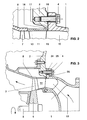
- FIG. 2 shows an enlarged section of FIG. 1, which roughly illustrates the size ratios of the gap widths.
- a sealing surface 17 to the gas inlet housing 1 is formed on the radially inner region of the gas outlet housing 2.
- a mounting gap 18 is arranged radially outside of this sealing surface 17 between the gas outlet housing 2 and the gas inlet housing 1.
- the inner ring 12 is supported on the gas inlet housing 1 in a rotationally secure manner by means of a plurality of positioning elements 19 designed as pins.
- the inner ring 12 For receiving the pins 19, the inner ring 12 has a corresponding number of thickenings 20 with first recesses 21 on its upstream side, while the gas inlet housing 1 has corresponding second recesses 22.
- Each of the first recesses 21 arranged in the thickenings 20 additionally has an inner gap 23 in the region of the pin 19 (FIG. 1).
- the nozzle ring 14 arranged directly in the flow channel 10 is exposed to the high exhaust gas temperatures during this process. Because its guide vanes 13 are relatively thin and the entire nozzle ring 14 also has a substantially smaller mass than the gas inlet housing 1, the gas outlet housing 2 or the cover ring 8, the nozzle ring 14 experiences a significantly greater temperature rise than the above-mentioned components surrounding it.
- the inventive design of the radial and the axial expansion gap 16, 15 allows the outer ring 11 of the nozzle ring 14 to expand freely in both the radial and the axial direction in accordance with the specific operating conditions.
- the substantially larger radial expansion of the material in the area between the outer ring 11 and the gas outlet housing 2 is compared to the possible axial expansion of the outer ring 11 and gas inlet housing 1 by the above. Ratio of the gap widths of about 4: 1 taken into account. In this way, the thermal stresses which form between the cover ring 8, the gas inlet housing 1, the gas outlet housing 2 and the nozzle ring 14 can be compensated.
- the nozzle ring 14 is on the one hand clamped diagonally between the cover ring 8 and the gas inlet housing 1 and on the other hand acts as a membrane between the components surrounding it. Due to the formation of the assembly gap 18, the sealing surface 17 is always in contact with the gas inlet housing 1. The sealing surface 17 prevents exhaust gas leakage to the environment. When using sheet metal as the material for the nozzle ring 14, its flexible design is additionally supported.
- the outer ring 11 is at full load of the diesel engine axially against the gas inlet housing 1 and radially against the gas outlet housing 2.
- the expansion gaps 15, 16 are closed during the operation of the exhaust gas turbine.
- no exhaust gas can penetrate into the cavity formed between the outer ring 11, the gas outlet housing 2 and the diffuser 8. In this way, both disturbances in the exhaust gas flow and gap losses are avoided, which results in higher efficiency.
- a clamping segment 24 which is axially form-fitting both with this and with the gas outlet housing 2 is arranged on the gas inlet housing 1 and is provided with recesses 25 designed as bores for the screws 4. Radial gaps 26 are formed between the clamping segment 24 and the gas inlet housing 1 (FIG. 3). As a result, the gas inlet housing 1 can also expand radially without increasing its operating voltages.
- the further arrangement and function of the components is analogous to the first embodiment.
Landscapes
- Engineering & Computer Science (AREA)
- General Engineering & Computer Science (AREA)
- Mechanical Engineering (AREA)
- Chemical & Material Sciences (AREA)
- Combustion & Propulsion (AREA)
- Chemical Kinetics & Catalysis (AREA)
- General Chemical & Material Sciences (AREA)
- Supercharger (AREA)
Applications Claiming Priority (2)
| Application Number | Priority Date | Filing Date | Title |
|---|---|---|---|
| DE19618314A DE19618314A1 (de) | 1996-05-08 | 1996-05-08 | Abgasturbine eines Abgasturboladers |
| DE19618314 | 1996-05-08 |
Publications (2)
| Publication Number | Publication Date |
|---|---|
| EP0806548A1 true EP0806548A1 (fr) | 1997-11-12 |
| EP0806548B1 EP0806548B1 (fr) | 2000-03-01 |
Family
ID=7793599
Family Applications (1)
| Application Number | Title | Priority Date | Filing Date |
|---|---|---|---|
| EP97810216A Expired - Lifetime EP0806548B1 (fr) | 1996-05-08 | 1997-04-11 | Turbine d'un turbocompresseur à gaz d'échappement |
Country Status (8)
| Country | Link |
|---|---|
| US (1) | US5868553A (fr) |
| EP (1) | EP0806548B1 (fr) |
| JP (1) | JP4082756B2 (fr) |
| KR (1) | KR100476516B1 (fr) |
| CN (1) | CN1105231C (fr) |
| CZ (1) | CZ290760B6 (fr) |
| DE (2) | DE19618314A1 (fr) |
| PL (1) | PL319809A1 (fr) |
Cited By (3)
| Publication number | Priority date | Publication date | Assignee | Title |
|---|---|---|---|---|
| EP0999349A2 (fr) | 1998-11-04 | 2000-05-10 | Asea Brown Boveri AG | Turbine axiale |
| US7086233B2 (en) | 2003-11-26 | 2006-08-08 | Siemens Power Generation, Inc. | Blade tip clearance control |
| US7708518B2 (en) | 2005-06-23 | 2010-05-04 | Siemens Energy, Inc. | Turbine blade tip clearance control |
Families Citing this family (24)
| Publication number | Priority date | Publication date | Assignee | Title |
|---|---|---|---|---|
| KR100293492B1 (ko) * | 1998-12-24 | 2001-07-12 | 이계철 | 부인 프로토콜을 이용한 전자 서명 확인 방법 |
| DE19925684A1 (de) * | 1999-06-04 | 2000-12-07 | Asea Brown Boveri | Vorrichtung zur Befestigung eines Turboladers an einer Basis |
| US6302647B1 (en) * | 2000-05-10 | 2001-10-16 | General Motors Corporation | Turbine inlet scroll |
| US6287091B1 (en) * | 2000-05-10 | 2001-09-11 | General Motors Corporation | Turbocharger with nozzle ring coupling |
| US6364606B1 (en) | 2000-11-08 | 2002-04-02 | Allison Advanced Development Company | High temperature capable flange |
| EP1543220B1 (fr) * | 2002-09-05 | 2008-05-21 | Honeywell International Inc. | Turbocompresseur comprenant un dispositif de tuyere variable |
| GB2401652B (en) * | 2003-05-14 | 2006-05-03 | Malcolm George Leavesley | Turbocharger apparatus having an exhaust gas recirculating system for preventing gas leakage from the turbocharger apparatus |
| US8602729B2 (en) * | 2007-07-27 | 2013-12-10 | Ansaldo Energia S.P.A. | Steam turbine stage |
| EP2080871A1 (fr) * | 2008-01-15 | 2009-07-22 | ABB Turbo Systems AG | Dispositif d'actionnement des aubes de guidage variables |
| WO2010085494A1 (fr) * | 2009-01-20 | 2010-07-29 | Williams International Co., L.L.C. | Turbocompresseur avec cartouche de tuyère de turbine |
| US20120023936A1 (en) * | 2010-07-30 | 2012-02-02 | Caterpillar Inc. | Nozzled turbocharger turbine |
| US8591184B2 (en) * | 2010-08-20 | 2013-11-26 | General Electric Company | Hub flowpath contour |
| DE102011080596A1 (de) * | 2011-08-08 | 2013-02-14 | Abb Turbo Systems Ag | Anordnung für ein Leiten eines Abgases in einer axial angeströmten Abgasturbine |
| JP6033154B2 (ja) | 2013-03-29 | 2016-11-30 | 三菱重工業株式会社 | 軸流回転機械、及びディフューザ |
| JP5889266B2 (ja) * | 2013-11-14 | 2016-03-22 | 三菱重工業株式会社 | タービン |
| US10066639B2 (en) | 2015-03-09 | 2018-09-04 | Caterpillar Inc. | Compressor assembly having a vaneless space |
| US10006341B2 (en) | 2015-03-09 | 2018-06-26 | Caterpillar Inc. | Compressor assembly having a diffuser ring with tabs |
| CN109098780B (zh) * | 2018-05-24 | 2024-05-14 | 中车大连机车研究所有限公司 | 一种涡轮增压器燃气废气进排气壳体 |
| DE102019101602A1 (de) * | 2019-01-23 | 2020-07-23 | Man Energy Solutions Se | Strömungsmaschine |
| US11136995B2 (en) * | 2019-04-05 | 2021-10-05 | Raytheon Technologies Corporation | Pre-diffuser for a gas turbine engine |
| US11384936B2 (en) | 2019-04-05 | 2022-07-12 | Raytheon Technologies Corporation | Pre-diffuser for a gas turbine engine |
| US11371704B2 (en) | 2019-04-05 | 2022-06-28 | Raytheon Technologies Corporation | Pre-diffuser for a gas turbine engine |
| CN115387906B (zh) * | 2022-05-12 | 2024-04-16 | 中国航发四川燃气涡轮研究院 | 低进口轮毂比发动机的进气承力框架连接结构及装配方法 |
| US12529322B1 (en) | 2024-11-08 | 2026-01-20 | Pratt & Whitney Canada Corp. | Gas turbine engine stator vane stage |
Citations (4)
| Publication number | Priority date | Publication date | Assignee | Title |
|---|---|---|---|---|
| DE928746C (de) * | 1952-12-04 | 1955-06-10 | Maschf Augsburg Nuernberg Ag | Leitapparat fuer Abgasturbogeblaese |
| US4477086A (en) * | 1982-11-01 | 1984-10-16 | United Technologies Corporation | Seal ring with slidable inner element bridging circumferential gap |
| US5395211A (en) * | 1994-01-14 | 1995-03-07 | United Technologies Corporation | Stator structure for a rotary machine |
| US5423659A (en) * | 1994-04-28 | 1995-06-13 | United Technologies Corporation | Shroud segment having a cut-back retaining hook |
Family Cites Families (10)
| Publication number | Priority date | Publication date | Assignee | Title |
|---|---|---|---|---|
| DE1036581B (de) * | 1956-09-22 | 1958-08-14 | Maschf Augsburg Nuernberg Ag | Befestigung des Duesenkranzes von Abgasturbinen |
| JPS58564B2 (ja) * | 1976-08-03 | 1983-01-07 | 三菱重工業株式会社 | 排気タ−ビン過給機 |
| GB2037901B (en) * | 1978-11-25 | 1982-07-28 | Rolls Royce | Nozzle guide vane assembly |
| EP0103260A3 (fr) * | 1982-09-06 | 1984-09-26 | Hitachi, Ltd. | Régulation du jeu des extrémités des aubes de turbine |
| DE3469205D1 (en) * | 1983-03-04 | 1988-03-10 | Bbc Brown Boveri & Cie | Connection between the hot and cold parts of an uncooled turbo charger |
| SU1480776A3 (ru) * | 1985-02-20 | 1989-05-15 | Ббц Аг Браун, Бовери Унд Ко. (Фирма) | Турбонагнетатель двигател внутреннего сгорани |
| JPS62135802U (fr) * | 1986-02-21 | 1987-08-26 | ||
| US5207565A (en) * | 1992-02-18 | 1993-05-04 | Alliedsignal Inc. | Variable geometry turbocharger with high temperature insert in turbine throat |
| US5271714A (en) * | 1992-07-09 | 1993-12-21 | General Electric Company | Turbine nozzle support arrangement |
| DE4223496A1 (de) * | 1992-07-17 | 1994-01-20 | Asea Brown Boveri | Vorrichtung zum Reduzieren der kinetischen Energie von berstenden Teilen |
-
1996
- 1996-05-08 DE DE19618314A patent/DE19618314A1/de not_active Withdrawn
-
1997
- 1997-04-11 EP EP97810216A patent/EP0806548B1/fr not_active Expired - Lifetime
- 1997-04-11 DE DE59701158T patent/DE59701158D1/de not_active Expired - Lifetime
- 1997-04-15 US US08/839,644 patent/US5868553A/en not_active Expired - Lifetime
- 1997-05-05 PL PL97319809A patent/PL319809A1/xx unknown
- 1997-05-06 CZ CZ19971376A patent/CZ290760B6/cs not_active IP Right Cessation
- 1997-05-07 JP JP11681797A patent/JP4082756B2/ja not_active Expired - Lifetime
- 1997-05-07 KR KR1019970017523A patent/KR100476516B1/ko not_active Expired - Lifetime
- 1997-05-08 CN CN97110900A patent/CN1105231C/zh not_active Expired - Lifetime
Patent Citations (4)
| Publication number | Priority date | Publication date | Assignee | Title |
|---|---|---|---|---|
| DE928746C (de) * | 1952-12-04 | 1955-06-10 | Maschf Augsburg Nuernberg Ag | Leitapparat fuer Abgasturbogeblaese |
| US4477086A (en) * | 1982-11-01 | 1984-10-16 | United Technologies Corporation | Seal ring with slidable inner element bridging circumferential gap |
| US5395211A (en) * | 1994-01-14 | 1995-03-07 | United Technologies Corporation | Stator structure for a rotary machine |
| US5423659A (en) * | 1994-04-28 | 1995-06-13 | United Technologies Corporation | Shroud segment having a cut-back retaining hook |
Cited By (4)
| Publication number | Priority date | Publication date | Assignee | Title |
|---|---|---|---|---|
| EP0999349A2 (fr) | 1998-11-04 | 2000-05-10 | Asea Brown Boveri AG | Turbine axiale |
| US6318961B1 (en) | 1998-11-04 | 2001-11-20 | Asea Brown Boveri Ag | Axial turbine |
| US7086233B2 (en) | 2003-11-26 | 2006-08-08 | Siemens Power Generation, Inc. | Blade tip clearance control |
| US7708518B2 (en) | 2005-06-23 | 2010-05-04 | Siemens Energy, Inc. | Turbine blade tip clearance control |
Also Published As
| Publication number | Publication date |
|---|---|
| JPH1047012A (ja) | 1998-02-17 |
| EP0806548B1 (fr) | 2000-03-01 |
| DE19618314A1 (de) | 1997-11-13 |
| KR970075266A (ko) | 1997-12-10 |
| US5868553A (en) | 1999-02-09 |
| CZ290760B6 (cs) | 2002-10-16 |
| JP4082756B2 (ja) | 2008-04-30 |
| CN1105231C (zh) | 2003-04-09 |
| PL319809A1 (en) | 1997-11-10 |
| CN1172893A (zh) | 1998-02-11 |
| CZ137697A3 (en) | 1997-11-12 |
| KR100476516B1 (ko) | 2005-06-16 |
| DE59701158D1 (de) | 2000-04-06 |
Similar Documents
| Publication | Publication Date | Title |
|---|---|---|
| EP0806548B1 (fr) | Turbine d'un turbocompresseur à gaz d'échappement | |
| EP1664489B1 (fr) | Turbine a gaz comprenant des moyens d'etancheite circulaires | |
| DE19703033A1 (de) | Abgasturbine eines Turboladers | |
| DE69309794T2 (de) | Düsenhalterung für Turbinen | |
| DE69926332T2 (de) | Bürstendichtung für eine Turbomaschine | |
| DE69321776T2 (de) | Gasturbine | |
| DE69932966T2 (de) | Leitschaufelanordnung für eine Turbomaschine | |
| DE10210866C1 (de) | Leitschaufelbefestigung in einem Strömungskanal einer Fluggasturbine | |
| EP1736635B1 (fr) | Système de transfert d'air entre le compresseur et la turbine d'une turbine à gaz | |
| EP3548705B1 (fr) | Turbochargeur | |
| DE102015219556A1 (de) | Diffusor für Radialverdichter, Radialverdichter und Turbomaschine mit Radialverdichter | |
| WO2010003537A2 (fr) | Boîtier de turbine pour turbocompresseur à gaz d'échappement d'un moteur à combustion interne | |
| EP0999349B1 (fr) | Turbine axiale | |
| EP0806547B1 (fr) | Turbine axiale pour turbocompresseurs | |
| DE102007050916A1 (de) | Verfahren und Vorrichtung zum Zusammenbau von Gasturbinen-Triebwerken | |
| EP3392463B1 (fr) | Turbomachine | |
| DE102010036071A1 (de) | Gehäuseseitige Struktur einer Turbomaschine | |
| EP1673519B1 (fr) | Dispositif d'etancheite pour une turbine a gaz | |
| DE102008029342A1 (de) | Turbinengehäuse für einen Abgasturbolader und Abgasturbolader | |
| EP3737850B1 (fr) | Filtre-amortisseur de bruit pour un turbocompresseur d'un moteur à combustion interne | |
| EP4496938B1 (fr) | Couronne de guidage pour une turbine radiale, turbine à gaz d'échappement et turbocompresseur à gaz d'échappement | |
| DE102023118123B4 (de) | Turbine und Turbolader mit einer Turbine | |
| DE3309812C2 (de) | Äußeres Gehäuse für ein Gasturbinentriebwerk | |
| DE4100225C2 (fr) | ||
| DE102021121533A1 (de) | Abgasturbolader mit verstellbarem Leitapparat |
Legal Events
| Date | Code | Title | Description |
|---|---|---|---|
| PUAI | Public reference made under article 153(3) epc to a published international application that has entered the european phase |
Free format text: ORIGINAL CODE: 0009012 |
|
| AK | Designated contracting states |
Kind code of ref document: A1 Designated state(s): DE FR GB |
|
| 17P | Request for examination filed |
Effective date: 19980420 |
|
| GRAG | Despatch of communication of intention to grant |
Free format text: ORIGINAL CODE: EPIDOS AGRA |
|
| GRAG | Despatch of communication of intention to grant |
Free format text: ORIGINAL CODE: EPIDOS AGRA |
|
| GRAH | Despatch of communication of intention to grant a patent |
Free format text: ORIGINAL CODE: EPIDOS IGRA |
|
| 17Q | First examination report despatched |
Effective date: 19990624 |
|
| GRAH | Despatch of communication of intention to grant a patent |
Free format text: ORIGINAL CODE: EPIDOS IGRA |
|
| GRAA | (expected) grant |
Free format text: ORIGINAL CODE: 0009210 |
|
| AK | Designated contracting states |
Kind code of ref document: B1 Designated state(s): DE FR GB |
|
| REF | Corresponds to: |
Ref document number: 59701158 Country of ref document: DE Date of ref document: 20000406 |
|
| GBT | Gb: translation of ep patent filed (gb section 77(6)(a)/1977) |
Effective date: 20000518 |
|
| ET | Fr: translation filed | ||
| PLBE | No opposition filed within time limit |
Free format text: ORIGINAL CODE: 0009261 |
|
| STAA | Information on the status of an ep patent application or granted ep patent |
Free format text: STATUS: NO OPPOSITION FILED WITHIN TIME LIMIT |
|
| 26N | No opposition filed | ||
| REG | Reference to a national code |
Ref country code: GB Ref legal event code: IF02 |
|
| REG | Reference to a national code |
Ref country code: FR Ref legal event code: CD Ref country code: FR Ref legal event code: CA |
|
| REG | Reference to a national code |
Ref country code: GB Ref legal event code: 732E |
|
| REG | Reference to a national code |
Ref country code: FR Ref legal event code: TP |
|
| REG | Reference to a national code |
Ref country code: FR Ref legal event code: PLFP Year of fee payment: 20 |
|
| PGFP | Annual fee paid to national office [announced via postgrant information from national office to epo] |
Ref country code: DE Payment date: 20160421 Year of fee payment: 20 Ref country code: GB Payment date: 20160421 Year of fee payment: 20 |
|
| PGFP | Annual fee paid to national office [announced via postgrant information from national office to epo] |
Ref country code: FR Payment date: 20160421 Year of fee payment: 20 |
|
| REG | Reference to a national code |
Ref country code: DE Ref legal event code: R071 Ref document number: 59701158 Country of ref document: DE |
|
| REG | Reference to a national code |
Ref country code: GB Ref legal event code: PE20 Expiry date: 20170410 |
|
| PG25 | Lapsed in a contracting state [announced via postgrant information from national office to epo] |
Ref country code: GB Free format text: LAPSE BECAUSE OF EXPIRATION OF PROTECTION Effective date: 20170410 |