EP0806562A1 - Culasse pour moteur à combustion interne - Google Patents
Culasse pour moteur à combustion interne Download PDFInfo
- Publication number
- EP0806562A1 EP0806562A1 EP97106334A EP97106334A EP0806562A1 EP 0806562 A1 EP0806562 A1 EP 0806562A1 EP 97106334 A EP97106334 A EP 97106334A EP 97106334 A EP97106334 A EP 97106334A EP 0806562 A1 EP0806562 A1 EP 0806562A1
- Authority
- EP
- European Patent Office
- Prior art keywords
- cylinder head
- head arrangement
- channels
- housing
- seal
- Prior art date
- Legal status (The legal status is an assumption and is not a legal conclusion. Google has not performed a legal analysis and makes no representation as to the accuracy of the status listed.)
- Granted
Links
Images


Classifications
-
- F—MECHANICAL ENGINEERING; LIGHTING; HEATING; WEAPONS; BLASTING
- F02—COMBUSTION ENGINES; HOT-GAS OR COMBUSTION-PRODUCT ENGINE PLANTS
- F02F—CYLINDERS, PISTONS OR CASINGS, FOR COMBUSTION ENGINES; ARRANGEMENTS OF SEALINGS IN COMBUSTION ENGINES
- F02F1/00—Cylinders; Cylinder heads
- F02F1/24—Cylinder heads
- F02F1/42—Shape or arrangement of intake or exhaust channels in cylinder heads
- F02F1/4214—Shape or arrangement of intake or exhaust channels in cylinder heads specially adapted for four or more valves per cylinder
-
- F—MECHANICAL ENGINEERING; LIGHTING; HEATING; WEAPONS; BLASTING
- F01—MACHINES OR ENGINES IN GENERAL; ENGINE PLANTS IN GENERAL; STEAM ENGINES
- F01M—LUBRICATING OF MACHINES OR ENGINES IN GENERAL; LUBRICATING INTERNAL COMBUSTION ENGINES; CRANKCASE VENTILATING
- F01M11/00—Component parts, details or accessories, not provided for in, or of interest apart from, groups F01M1/00 - F01M9/00
- F01M11/02—Arrangements of lubricant conduits
-
- F—MECHANICAL ENGINEERING; LIGHTING; HEATING; WEAPONS; BLASTING
- F01—MACHINES OR ENGINES IN GENERAL; ENGINE PLANTS IN GENERAL; STEAM ENGINES
- F01M—LUBRICATING OF MACHINES OR ENGINES IN GENERAL; LUBRICATING INTERNAL COMBUSTION ENGINES; CRANKCASE VENTILATING
- F01M9/00—Lubrication means having pertinent characteristics not provided for in, or of interest apart from, groups F01M1/00 - F01M7/00
- F01M9/10—Lubrication of valve gear or auxiliaries
- F01M9/104—Lubrication of valve gear or auxiliaries of tappets
-
- F—MECHANICAL ENGINEERING; LIGHTING; HEATING; WEAPONS; BLASTING
- F01—MACHINES OR ENGINES IN GENERAL; ENGINE PLANTS IN GENERAL; STEAM ENGINES
- F01M—LUBRICATING OF MACHINES OR ENGINES IN GENERAL; LUBRICATING INTERNAL COMBUSTION ENGINES; CRANKCASE VENTILATING
- F01M9/00—Lubrication means having pertinent characteristics not provided for in, or of interest apart from, groups F01M1/00 - F01M7/00
- F01M9/10—Lubrication of valve gear or auxiliaries
- F01M9/105—Lubrication of valve gear or auxiliaries using distribution conduits
-
- F—MECHANICAL ENGINEERING; LIGHTING; HEATING; WEAPONS; BLASTING
- F01—MACHINES OR ENGINES IN GENERAL; ENGINE PLANTS IN GENERAL; STEAM ENGINES
- F01M—LUBRICATING OF MACHINES OR ENGINES IN GENERAL; LUBRICATING INTERNAL COMBUSTION ENGINES; CRANKCASE VENTILATING
- F01M9/00—Lubrication means having pertinent characteristics not provided for in, or of interest apart from, groups F01M1/00 - F01M7/00
- F01M9/10—Lubrication of valve gear or auxiliaries
- F01M9/108—Lubrication of valve gear or auxiliaries of auxiliaries
-
- F—MECHANICAL ENGINEERING; LIGHTING; HEATING; WEAPONS; BLASTING
- F02—COMBUSTION ENGINES; HOT-GAS OR COMBUSTION-PRODUCT ENGINE PLANTS
- F02B—INTERNAL-COMBUSTION PISTON ENGINES; COMBUSTION ENGINES IN GENERAL
- F02B2275/00—Other engines, components or details, not provided for in other groups of this subclass
- F02B2275/18—DOHC [Double overhead camshaft]
-
- F—MECHANICAL ENGINEERING; LIGHTING; HEATING; WEAPONS; BLASTING
- F02—COMBUSTION ENGINES; HOT-GAS OR COMBUSTION-PRODUCT ENGINE PLANTS
- F02F—CYLINDERS, PISTONS OR CASINGS, FOR COMBUSTION ENGINES; ARRANGEMENTS OF SEALINGS IN COMBUSTION ENGINES
- F02F1/00—Cylinders; Cylinder heads
- F02F1/24—Cylinder heads
- F02F1/242—Arrangement of spark plugs or injectors
-
- F—MECHANICAL ENGINEERING; LIGHTING; HEATING; WEAPONS; BLASTING
- F02—COMBUSTION ENGINES; HOT-GAS OR COMBUSTION-PRODUCT ENGINE PLANTS
- F02F—CYLINDERS, PISTONS OR CASINGS, FOR COMBUSTION ENGINES; ARRANGEMENTS OF SEALINGS IN COMBUSTION ENGINES
- F02F1/00—Cylinders; Cylinder heads
- F02F1/24—Cylinder heads
- F02F2001/244—Arrangement of valve stems in cylinder heads
- F02F2001/245—Arrangement of valve stems in cylinder heads the valve stems being orientated at an angle with the cylinder axis
Definitions
- the invention relates to a cylinder head arrangement according to the preamble of patent claim 1.
- DE 44 21 057 C1 shows a generic cylinder head arrangement in which a basic housing is placed on a cylinder block and screwed to it.
- the basic housing has raised outer walls, on which a hood-like cover is placed, which at the same time accommodates the upper bearing halves for the camshaft bearing.
- a tappet housing is inserted into the base housing within the outer walls of the basic housing and serves to receive and guide the tappets of the gas exchange valves.
- an oil guide channel is formed, which serves to guide the oil and supply the bucket tappets. It is possible to supply the bucket tappets for lubrication and to act on any hydraulic valve lash adjuster that may be present.
- variable valve control systems are increasingly being used to improve performance and exhaust gas behavior, with which, for example, the phase position of the valve control times and / or the valve lift can be varied or switched. Different systems are used, however are usually hydraulically controlled and must accordingly be integrated into the oil circuit of the internal combustion engine or the cylinder head.
- the invention is therefore based on the object of improving a generic cylinder head arrangement in such a way that improved oil guidance within the cylinder head arrangement is ensured, which is able to supply a large number of consumers and at the same time is simple to produce. Labor and cost-intensive drilling is to be largely avoided.
- Such an oil guide is particularly easy to manufacture and to connect to the lubricating oil supply of the overall internal combustion engine if one of the Housing components is a basic housing that has gas exchange channels and valve guides and is placed on the cylinder block of the internal combustion engine.
- the oil supply to the internal combustion engine takes place in a manner known per se through riser bores within the cylinder block, which are connected to the oil pump of the internal combustion engine.
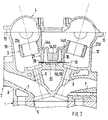
- An internal combustion engine has a cylinder head arrangement placed on a cylinder block 1, the housing of which is composed of three housing components, a basic housing 2, a tappet housing 3 and a cylinder head cover 4.
- the internal combustion engine is in the form of a cylinder bank of a six-cylinder boxer engine with four valves each Cylinder and two overhead camshafts shown.
- This internal combustion engine consequently has three cylinder bores 5 per cylinder bank.
- Each of these cylinder bores 5 does not work via four guided in valve guides 6 controlled gas exchange valves (two intake valves, two exhaust valves) and corresponding gas exchange channels 7.
- the gas exchange channels 7 and valve guides 6 are integrated in a basic block 8 of the basic housing 2, to which a chain case 9 is connected at the end.
- Outer walls 10, 11, 12 extend from the base block 8 of the housing 2 and are raised up to a common parting plane 13.
- the chain case 9 is enclosed by outer walls 14, which also extend to this parting plane 13.
- three shafts 15 are formed, each starting from a flange surface 16 and opening into one of the three cylinder bores 5. These three shafts 15 serve to receive a spark plug, an injection valve or a glow plug.
- four lower bearing block halves 17 are furthermore formed for each camshaft (not shown in more detail) or for each valve row, which lie opposite one another in pairs.
- the bucket tappet housing 3 is inserted into the interior of the basic housing 2, which is delimited by the outer walls 10 to 12 and the chain case 9, and rests with a flange surface 18 on the flange surface 16 of the basic housing 2.
- the two flange surfaces 16 and 18 form a common flange plane 19 and are separated from one another by an interposed seal 20.
- the bucket tappet housing 3 is formed in one piece and has a central web 21 which has the flange surface 19 and with which four tappet guides 22a to 22d are connected to each cylinder bore 5 and are each combined in pairs. In the central web 21, three bores 23 are formed, which are aligned with the shafts 15 of the basic housing 2.
- the cylinder head arrangement is completed by the cylinder head cover 4, which is placed on the outer walls 10 to 12 and 14.
- the upper bearing block halves 24 are formed, which together with the lower bearing block halves 17 formed in the basic housing 2 support the camshafts, which are not shown in detail.
- a dashed pressure channel 25 opens into the flange surface 16 of the basic housing and is connected in a manner not shown to a riser of the oil supply in the cylinder block 1.
- a short recess 26 cast into the flange surface 16 extends from this pressure channel 25 and is connected via an opening 27 in the seal 20 to a blind bore 28 in the central web 21 of the bucket tappet housing 3.
- This blind bore 28 is connected via an annular channel 29 to the input side of a control valve 30 inserted into the central web 21 (FIG. 5).
- This control valve 30, also shown schematically in FIG. 6, is connected to one of its outputs via a check valve 31 with the interior of the cylinder head arrangement.
- the second outlet of the control valve 30 is connected via a bore 32 to a cast-in recess 33 in the flange surface 19 of the bucket tappet housing 3.
- this depression 33 is connected via an opening 34 in the seal 20 to a further depression 35 in the flange surface 16 of the basic housing.
- the other end of the recess 35 is connected via a further opening 36 to a recess 37 in the flange surface 19 which is connected to a recess 39 in the flange surface 16 via a passage 38 in the seal 20.
- the depression 33 is additionally connected to a depression 41 in the flange surface 16 via the bore 32 and an opening 40 in the seal 20.
- the depressions 33 and 37 in the flange surface 19 and the depressions 35, 39 and 41 in the flange surface 16 are separated from one another by the seal 20 inserted between the two flange surfaces. Pressure medium transitions are only possible in the area of the openings 27, 34, 36, 38 and 40.
- the depressions 33 and 37 on the one hand and 35, 39 and 41 on the other hand thus form together with the seal 20 and the openings 27, 34, 36, 38 and 40 a channel 42 which is connected to the control connection of the control valve 30.
- this channel 42 is connected to the respective tappet guide 22b via a channel 43b in the central web 21 and an oblique bore 44b emanating therefrom and serves to supply pressure medium and lubricant to the bucket tappets 45b shown schematically in FIG.
- These tappets can be used as conventional tappets known per se or as also known switchable or switchable tappets can be formed.
- a cup tappet which can be switched off is understood to be one with which the valve lift of the associated gas exchange valve can be switched on or off completely.
- Switchable bucket tappets are to be understood as those with which the valve lift of the associated gas exchange valve can be varied in at least two stages.
- a second pressure channel 46 which is connected to the oil supply in the cylinder block 1, opens into the flange surface 16 of the basic housing 2 and has a short recess 47, an opening 48 in the seal 20 and a blind bore 49 with the pressure connection of a second control valve 50 inserted into the central web 21 connected is.
- This second control valve 50 shown schematically in FIG. 6, is connected to the interior of the cylinder head arrangement in a manner analogous to the first control valve 30 via a check valve 51.
- the control port is connected to the first control valve 30 via a bore 52 with a recess 53 in the flange surface 19. This recess 53 extends over almost the entire length of the flange surface.
- each of the three cylinder bores 5 or bores 23 three channels 43a, 43c and 43d each open into this recess 53. From each of these channels in the central web 21 there is an oblique bore 44a, 44c and 44d, which serves to supply the associated tappet guide 22a, 22c, 22d or the cup tappet 45a, 45c and 45d.
- tappet elements known per se can also be used in a switchable, switchable or non-switchable design. It can make sense here if, for example, the respectively assigned inlet valve is provided with a switchable or switchable tappet element, while the assigned outlet valves are operated with non-switchable tappet elements.
- the depression 53 thus forms, together with the seal 20, a channel 54 which is connected to the control connection of the second control valve 50.
- This channel 54 together with the channels 43a, 43c and 43d and the oblique bores 44a, 44c and 44d serve to supply pressure and lubricant to the tappet guides 22a, 22c and 22d or the bucket tappets 45a, 45c and 45d.
- the annular channel 29 on the first control valve 30 is connected via a bore 55 to a short recess 56 in the flange surface 19.
- This depression 56 is in turn connected via an opening 57 in the seal 20 to a depression 58 in the flange surface, which leads into the area of the chain case 9.
- oil supply to components on the end face, which in this exemplary embodiment are arranged in the region of the chain case is possible.
- This can be, for example, hydraulically actuated chain tensioners of the timing drive. It is also possible to apply devices for changing the phase position of the camshafts (camshaft phase adjuster) via this channel section.
- the oil supply to the cylinder head arrangement is shown schematically in FIG. 6 for the four bucket tappets 45a to 45d (stroke transmission elements) of two cylinders.
- the bucket tappets 45a and 45b are each designed as switchable elements (stroke changeover or stroke cutoff).
- the cup tappets 45c and 45d assigned to the outlet valves cannot be switched in this exemplary embodiment.
- the oil pump 60 of the internal combustion engine delivers oil from the oil pan 61 of the internal combustion engine via a riser 62 in the cylinder block 1 into the cylinder head arrangement.
- the two switching valves 30 and 50 are pressurized on the inlet side in the manner described above. In the unswitched state, the inlet side of both switching valves is connected to the check valve 31 or 51.
- the check valves are designed so that they only open when a predetermined pressure is exceeded. This opening pressure is less than the switching pressure of the bucket tappets or the switching elements integrated in the circuit. Together with a throttle line 63 or 64 between the riser 62 and the channel 42 or 54, it is thus ensured that a pressure required for the lubrication within the cylinder head arrangement is not undercut.
- the inlet side of both switching valves 30, 50 is connected to the control connection or the bore 32 or 52.
- the respectively assigned channel 42 or 54 is thus also connected the delivery pressure of the oil pump 60 is applied. This makes it possible to switch over the assigned switchable bucket tappets (stroke transmission elements).
- cup tappet elements in their respective embodiment via the independent channel sections or channels formed in the flange plane 19. It is easily possible to supply other consumers with pressure medium or lubricant within the cylinder head arrangement. This can be, for example, all lubrication points in the area of the valve train. It is also possible to supply different consumers with pressure medium or lubricant by separating the individual channels or channel sections. These can in particular be switchable valve lift transmission elements, such as rocker arms, rocker arms or the like. It is also possible, as an alternative or in addition, to supply pressure to the valve phase control elements via one of these channels or channel sections.
- the arrangement of different channels and channel sections within the flange level or within the flange surfaces separated by the seal offers the possibility of supplying different consumers with lubricant or pressure medium independently of one another.
- This consumer is supplied with lubricating oil via the first lines.
- Hydraulic valve lash compensation elements can then also be applied via these first lines, for example.
- the pressure control of switching elements can then take place via a second line.
Landscapes
- Engineering & Computer Science (AREA)
- Mechanical Engineering (AREA)
- General Engineering & Computer Science (AREA)
- Chemical & Material Sciences (AREA)
- Combustion & Propulsion (AREA)
- Lubrication Of Internal Combustion Engines (AREA)
- Valve-Gear Or Valve Arrangements (AREA)
- Cylinder Crankcases Of Internal Combustion Engines (AREA)
Applications Claiming Priority (2)
| Application Number | Priority Date | Filing Date | Title |
|---|---|---|---|
| DE19618401A DE19618401C1 (de) | 1996-05-08 | 1996-05-08 | Zylinderkopfanordnung einer Brennkraftmaschine |
| DE19618401 | 1996-05-08 |
Publications (2)
| Publication Number | Publication Date |
|---|---|
| EP0806562A1 true EP0806562A1 (fr) | 1997-11-12 |
| EP0806562B1 EP0806562B1 (fr) | 2001-03-21 |
Family
ID=7793649
Family Applications (1)
| Application Number | Title | Priority Date | Filing Date |
|---|---|---|---|
| EP97106334A Expired - Lifetime EP0806562B1 (fr) | 1996-05-08 | 1997-04-17 | Culasse pour moteur à combustion interne |
Country Status (5)
| Country | Link |
|---|---|
| US (1) | US5845616A (fr) |
| EP (1) | EP0806562B1 (fr) |
| JP (1) | JPH1047155A (fr) |
| KR (1) | KR100456766B1 (fr) |
| DE (2) | DE19618401C1 (fr) |
Families Citing this family (10)
| Publication number | Priority date | Publication date | Assignee | Title |
|---|---|---|---|---|
| JPH10331709A (ja) * | 1997-05-29 | 1998-12-15 | Suzuki Motor Corp | 内燃機関のシリンダヘッド構造 |
| US6099374A (en) * | 1997-08-14 | 2000-08-08 | Sanshin Kogyo Kabushiki Kaisha | Lubrication and oil drain system for 4 cycle outboard motor |
| US6123055A (en) * | 1998-02-25 | 2000-09-26 | Isuzu Motors Limited | Cylinder head structure |
| DE19828307A1 (de) * | 1998-06-25 | 1999-12-30 | Porsche Ag | Zylinderkopf einer Brennkraftmaschine |
| US6257188B1 (en) * | 1998-09-02 | 2001-07-10 | Honda Giken Kogyo Kabushiki Kaisha | Structure for mounting cylinder head cover of internal combustion engine |
| JP4627304B2 (ja) * | 2007-02-01 | 2011-02-09 | 愛知機械工業株式会社 | シリンダヘッドおよびこれを備える内燃機関 |
| DE102007062280A1 (de) * | 2007-12-21 | 2009-06-25 | Daimler Ag | Zylinderkopfeinheit |
| EP2177723A1 (fr) * | 2008-10-17 | 2010-04-21 | GE Jenbacher GmbH & Co. OHG | Guidage de poussoir |
| US8371260B2 (en) * | 2010-05-17 | 2013-02-12 | GM Global Technology Operations LLC | Cylinder head drain and vent |
| US10113502B2 (en) * | 2015-09-08 | 2018-10-30 | Ford Global Technologies, Llc | Cylinder head for an internal combustion engine |
Citations (3)
| Publication number | Priority date | Publication date | Assignee | Title |
|---|---|---|---|---|
| FR2552820A1 (fr) * | 1983-10-04 | 1985-04-05 | Honda Motor Co Ltd | Culasse de cylindre pour moteur a combustion interne du type a double arbre a cames en tete |
| EP0318303A1 (fr) * | 1987-11-25 | 1989-05-31 | Honda Giken Kogyo Kabushiki Kaisha | Dispositif de commande de soupape pour moteur à combustion interne |
| DE4435299A1 (de) * | 1994-10-01 | 1996-04-04 | Bayerische Motoren Werke Ag | Reihen-Zylinderkopf mit gegossenem Öl-Längskanal |
Family Cites Families (2)
| Publication number | Priority date | Publication date | Assignee | Title |
|---|---|---|---|---|
| JPH07127419A (ja) * | 1993-10-29 | 1995-05-16 | Suzuki Motor Corp | エンジンのオイル通路装置 |
| DE4421057C1 (de) * | 1994-06-16 | 1995-09-14 | Porsche Ag | Zylinderkopfanordnung einer Brennkraftmaschine |
-
1996
- 1996-05-08 DE DE19618401A patent/DE19618401C1/de not_active Expired - Fee Related
-
1997
- 1997-04-17 EP EP97106334A patent/EP0806562B1/fr not_active Expired - Lifetime
- 1997-04-17 DE DE59703163T patent/DE59703163D1/de not_active Expired - Fee Related
- 1997-05-07 KR KR1019970017495A patent/KR100456766B1/ko not_active Expired - Fee Related
- 1997-05-07 JP JP9117148A patent/JPH1047155A/ja active Pending
- 1997-05-08 US US08/853,345 patent/US5845616A/en not_active Expired - Fee Related
Patent Citations (3)
| Publication number | Priority date | Publication date | Assignee | Title |
|---|---|---|---|---|
| FR2552820A1 (fr) * | 1983-10-04 | 1985-04-05 | Honda Motor Co Ltd | Culasse de cylindre pour moteur a combustion interne du type a double arbre a cames en tete |
| EP0318303A1 (fr) * | 1987-11-25 | 1989-05-31 | Honda Giken Kogyo Kabushiki Kaisha | Dispositif de commande de soupape pour moteur à combustion interne |
| DE4435299A1 (de) * | 1994-10-01 | 1996-04-04 | Bayerische Motoren Werke Ag | Reihen-Zylinderkopf mit gegossenem Öl-Längskanal |
Also Published As
| Publication number | Publication date |
|---|---|
| KR970075288A (ko) | 1997-12-10 |
| JPH1047155A (ja) | 1998-02-17 |
| KR100456766B1 (ko) | 2005-04-06 |
| DE19618401C1 (de) | 1997-07-03 |
| US5845616A (en) | 1998-12-08 |
| EP0806562B1 (fr) | 2001-03-21 |
| DE59703163D1 (de) | 2001-04-26 |
Similar Documents
| Publication | Publication Date | Title |
|---|---|---|
| DE102012219851B4 (de) | Viertaktmotor | |
| DE112020004972T5 (de) | Variable Ventiltriebsvorrichtung eines Motors und Motor | |
| DE3436426A1 (de) | Zylinderkopf fuer eine brennkraftmaschine mit zwei obenliegenden nockenwellen | |
| EP0806552B1 (fr) | Culasse pour moteur à combustion interne | |
| EP0688946B1 (fr) | Agencement d'une culasse d'un moteur à combustion interne | |
| DE102009009149B4 (de) | Ölsystem zum wahlweisen Abschalten von Ventilen für angegebene Zylinder | |
| DE19618401C1 (de) | Zylinderkopfanordnung einer Brennkraftmaschine | |
| DE19819431B4 (de) | Ölkanalstruktur für einen Motor | |
| DE102010045745A1 (de) | Ablauf und Entlüftung für einen Zylinderkopf | |
| DE69414557T2 (de) | Zylinderkopfanordnung für eine Mehrventil-Brennkraftmaschine mit obenliegender Nockenwelle | |
| EP0515925B1 (fr) | Culasse pour moteur à combustion | |
| DE69519326T2 (de) | Brennkraftmaschine | |
| DE19723342C1 (de) | Zylinderkopf und Gießkern zur Herstellung von Ölkanälen | |
| DE3604667A1 (de) | Gegossener zylinderkopf fuer eine mehrzylindrige reihen-brennkraftmaschine | |
| EP0845582B1 (fr) | Commande de soupape pour un moteur à combustion interne équipé de soupapes à levée pour le transfert de charge | |
| DE69105568T2 (de) | Kühlkreislauf eines Zylinderkopfes für eine Brennkraftmaschine. | |
| EP0180847B1 (fr) | Boîtier de commande pour culasse des moteurs à combustion interne avec des soupapes agencées en parallèle | |
| EP0744531B1 (fr) | Culasse pour une machine à combustion interne | |
| DE102004034912B4 (de) | Zylinderkopfstruktur eines Motors | |
| DE2943560C2 (de) | Vorrichtung für einen Verbrennungsmotor | |
| EP1155223B1 (fr) | Moteur a combustion interne multicylindre pourvu de soupapes d'echange de gaz actionnees par des actionneurs electromagnetiques | |
| DE69315321T2 (de) | Brennkraftmaschine | |
| EP1101028B1 (fr) | Culasse pour moteur a combustion interne a piston | |
| EP0353577B1 (fr) | Culasse pour moteur à combustion interne | |
| DE4335509C2 (de) | Nockenwellen-Ventilsteuerung für eine Brennkraftmaschine mit zwei Zylinderreihen und zwei Nockenwellen |
Legal Events
| Date | Code | Title | Description |
|---|---|---|---|
| PUAI | Public reference made under article 153(3) epc to a published international application that has entered the european phase |
Free format text: ORIGINAL CODE: 0009012 |
|
| AK | Designated contracting states |
Kind code of ref document: A1 Designated state(s): DE FR GB IT |
|
| 17P | Request for examination filed |
Effective date: 19980407 |
|
| GRAG | Despatch of communication of intention to grant |
Free format text: ORIGINAL CODE: EPIDOS AGRA |
|
| GRAG | Despatch of communication of intention to grant |
Free format text: ORIGINAL CODE: EPIDOS AGRA |
|
| GRAH | Despatch of communication of intention to grant a patent |
Free format text: ORIGINAL CODE: EPIDOS IGRA |
|
| 17Q | First examination report despatched |
Effective date: 20000724 |
|
| GRAH | Despatch of communication of intention to grant a patent |
Free format text: ORIGINAL CODE: EPIDOS IGRA |
|
| ITF | It: translation for a ep patent filed | ||
| GRAA | (expected) grant |
Free format text: ORIGINAL CODE: 0009210 |
|
| AK | Designated contracting states |
Kind code of ref document: B1 Designated state(s): DE FR GB IT |
|
| GBT | Gb: translation of ep patent filed (gb section 77(6)(a)/1977) |
Effective date: 20010402 |
|
| REF | Corresponds to: |
Ref document number: 59703163 Country of ref document: DE Date of ref document: 20010426 |
|
| ET | Fr: translation filed | ||
| REG | Reference to a national code |
Ref country code: GB Ref legal event code: IF02 |
|
| PLBE | No opposition filed within time limit |
Free format text: ORIGINAL CODE: 0009261 |
|
| STAA | Information on the status of an ep patent application or granted ep patent |
Free format text: STATUS: NO OPPOSITION FILED WITHIN TIME LIMIT |
|
| 26N | No opposition filed | ||
| PGFP | Annual fee paid to national office [announced via postgrant information from national office to epo] |
Ref country code: FR Payment date: 20060411 Year of fee payment: 10 |
|
| PGFP | Annual fee paid to national office [announced via postgrant information from national office to epo] |
Ref country code: GB Payment date: 20060420 Year of fee payment: 10 |
|
| PGFP | Annual fee paid to national office [announced via postgrant information from national office to epo] |
Ref country code: IT Payment date: 20060430 Year of fee payment: 10 |
|
| GBPC | Gb: european patent ceased through non-payment of renewal fee |
Effective date: 20070417 |
|
| PG25 | Lapsed in a contracting state [announced via postgrant information from national office to epo] |
Ref country code: GB Free format text: LAPSE BECAUSE OF NON-PAYMENT OF DUE FEES Effective date: 20070417 |
|
| PG25 | Lapsed in a contracting state [announced via postgrant information from national office to epo] |
Ref country code: FR Free format text: LAPSE BECAUSE OF NON-PAYMENT OF DUE FEES Effective date: 20070430 |
|
| PGFP | Annual fee paid to national office [announced via postgrant information from national office to epo] |
Ref country code: DE Payment date: 20090317 Year of fee payment: 13 |
|
| PG25 | Lapsed in a contracting state [announced via postgrant information from national office to epo] |
Ref country code: IT Free format text: LAPSE BECAUSE OF NON-PAYMENT OF DUE FEES Effective date: 20070417 |
|
| PG25 | Lapsed in a contracting state [announced via postgrant information from national office to epo] |
Ref country code: DE Free format text: LAPSE BECAUSE OF NON-PAYMENT OF DUE FEES Effective date: 20101103 |