EP0806587A1 - Unité piston-cyclindre avec caractéristiques d'amortissement variables en fonction de la distance - Google Patents
Unité piston-cyclindre avec caractéristiques d'amortissement variables en fonction de la distance Download PDFInfo
- Publication number
- EP0806587A1 EP0806587A1 EP97106798A EP97106798A EP0806587A1 EP 0806587 A1 EP0806587 A1 EP 0806587A1 EP 97106798 A EP97106798 A EP 97106798A EP 97106798 A EP97106798 A EP 97106798A EP 0806587 A1 EP0806587 A1 EP 0806587A1
- Authority
- EP
- European Patent Office
- Prior art keywords
- piston
- pistons
- damping force
- cylinder unit
- bypass
- Prior art date
- Legal status (The legal status is an assumption and is not a legal conclusion. Google has not performed a legal analysis and makes no representation as to the accuracy of the status listed.)
- Granted
Links
- 238000013016 damping Methods 0.000 title claims abstract description 59
- 230000001419 dependent effect Effects 0.000 title abstract description 7
- 239000011324 bead Substances 0.000 claims description 12
- 230000007704 transition Effects 0.000 claims description 6
- 238000007373 indentation Methods 0.000 abstract 1
- 230000000694 effects Effects 0.000 description 4
- 239000006096 absorbing agent Substances 0.000 description 3
- 230000035939 shock Effects 0.000 description 3
Images


Classifications
-
- F—MECHANICAL ENGINEERING; LIGHTING; HEATING; WEAPONS; BLASTING
- F16—ENGINEERING ELEMENTS AND UNITS; GENERAL MEASURES FOR PRODUCING AND MAINTAINING EFFECTIVE FUNCTIONING OF MACHINES OR INSTALLATIONS; THERMAL INSULATION IN GENERAL
- F16J—PISTONS; CYLINDERS; SEALINGS
- F16J1/00—Pistons; Trunk pistons; Plungers
-
- F—MECHANICAL ENGINEERING; LIGHTING; HEATING; WEAPONS; BLASTING
- F16—ENGINEERING ELEMENTS AND UNITS; GENERAL MEASURES FOR PRODUCING AND MAINTAINING EFFECTIVE FUNCTIONING OF MACHINES OR INSTALLATIONS; THERMAL INSULATION IN GENERAL
- F16F—SPRINGS; SHOCK-ABSORBERS; MEANS FOR DAMPING VIBRATION
- F16F9/00—Springs, vibration-dampers, shock-absorbers, or similarly-constructed movement-dampers using a fluid or the equivalent as damping medium
- F16F9/32—Details
- F16F9/34—Special valve constructions; Shape or construction of throttling passages
- F16F9/346—Throttling passages in the form of slots arranged in cylinder walls
-
- F—MECHANICAL ENGINEERING; LIGHTING; HEATING; WEAPONS; BLASTING
- F16—ENGINEERING ELEMENTS AND UNITS; GENERAL MEASURES FOR PRODUCING AND MAINTAINING EFFECTIVE FUNCTIONING OF MACHINES OR INSTALLATIONS; THERMAL INSULATION IN GENERAL
- F16F—SPRINGS; SHOCK-ABSORBERS; MEANS FOR DAMPING VIBRATION
- F16F2230/00—Purpose; Design features
- F16F2230/42—Multiple pistons
Definitions
- the invention relates to a piston-cylinder unit according to the preamble of claim 1.
- a piston-cylinder unit which is designed as an end position damper.
- This end position damper comprises a cylindrical pressure tube which is delimited axially on the one hand by a bottom and on the other hand by a seal guide unit.
- the piston-cylinder unit includes a piston system that divides the pressure pipe into two working spaces, the piston system having flow channels that are equipped with check valves.
- the piston-cylinder unit has a stroke range, which is formed by the relative position between the piston rod and the pressure pipe, in which there is no damping force in each case.
- DE-PS 12 51 165 describes a shock absorber which has a piston on a piston rod, in which the piston consists of two piston heads.
- the piston interacts with a rod attached to the bottom of the shock absorber.
- the piston rod holds the piston on the outside diameter, so that a central opening for each piston head can be formed in the middle.
- These central openings act as throttles with the rod, with non-return valves being arranged on the piston heads, which ensure that no damping force is generated starting from the respective end positions.
- the shock absorber In a medium stroke range, the shock absorber likewise does not generate any damping force, since the rod has a diameter reduction over a defined length, so that the center openings can produce practically no damping forces.
- the damping force is generated only by the current cross-section, which results from the covering of a central opening with the rod. Due to their check valves, the piston heads are not involved in the damping force effect.
- DE 34 46 133 discloses a vibration damper with variable damping force, in which a bypass can be switched within a damping valve device by means of an adjusting device so that a damping valve system within the damping valve device generates a damping force or both damping valve systems are effective.
- the object of the present invention is to realize a piston-cylinder unit that generates a load-dependent damping force independently of an external control.
- the object is achieved in that the two pistons are spaced apart in relation to the bypass, so that depending on the Stroke position of both pistons, one piston or none of the pistons generates / generate a damping force, the two pistons damping outside the bypass in both stroke directions.
- the damping force is adapted to the requirements without the need for complex adjusting means.
- Both pistons are provided with damping valves for both flow directions. A more or less strongly asymmetrical damping force characteristic can be achieved by a different damping valve design.
- the bypass consists of at least one bead with an essentially axial alignment in the cylinder tube.
- This type of bypass can be shaped relatively easily and with sufficient precision.
- the cross-section of the bead (s) is / are designed in stages depending on the stroke position.
- the grading of the bypass cross-section in connection with the differently designed damping valves enables great variability with regard to the desired damping force map.
- the cross-sectional steps of the bead (s) are designed with transition cross-sections that cause a continuous change in cross-section, practically unlimited possibilities are available.
- the piston-cylinder unit comprises, inter alia, a cylinder 3, which at one end of a bottom 5 and at the other end of one Piston rod guide 7 is completed relative to the environment.
- a piston rod 9 with a first piston 11 and a second piston 13 is arranged within the cylinder 3.
- the two pistons 11; 13 are held by a sleeve 15 at a distance A, whereby three working spaces 17; 19; 21 arise.
- the two work rooms 17; 21 are dependent in their spatial size on the current stroke position of the piston rod 9, while the working space 19 between the pistons 11, 13 has a constant volume.
- a gas-filled compensation chamber 23 extends, which is separated from the working chamber 21 by a separating piston 25.
- the pistons are each on both sides with damping valves 27; 29; 31; 33 provided so that the pistons 11; 13 can generate a damping force.
- damping valves 27; 29; 31; 33 provided so that the pistons 11; 13 can generate a damping force.
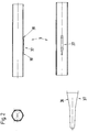
- the piston-cylinder unit 1 has at least one bypass 35 which is formed by at least one bead 37 which extends essentially in the axial direction.
- the cylinder 3 is shown as an individual part in several views and detail sections. It can be clearly seen that the bead (s) 37 is / are designed to be stepped depending on the stroke position. In the further description, one bead is always described, but it is to be assumed tacitly that several beads with this configuration are also possible.
- the beads form transition cross sections 39, the transition cross sections being formed by an obliquely running contour of at least one bead edge.
- the relationship of the piston position to the bypass with the path-dependent damping force is easy to understand. It is assumed that the bypass is longer than the distance between the two pistons 11; 13 or their piston seals. If both pistons are within the bypass, the minimum damping force of the piston-cylinder unit is present, because the damping medium can flow between the working spaces 17; 21 can be replaced without having to flow through the damping valves.
- the damping force need not necessarily be zero. In any case, an extremely comfortable damping force setting is obtained, this point corresponding to the stroke position of the piston rod with a normal or reduced loading of the motor vehicle.
- both pistons are outside the bypass, the effective damping forces of the pistons overlap to form a hydraulic pressure stop HDA and HZA in relation to the direction of pull and pressure, since the pistons are also hydraulically arranged in series.
- the damping medium must flow, for example, in the pressure direction from the working space 21 via the damping valve 31 into the working space 19 and from there via the damping valve 27 into the working space 17.
Landscapes
- Engineering & Computer Science (AREA)
- General Engineering & Computer Science (AREA)
- Mechanical Engineering (AREA)
- Chemical & Material Sciences (AREA)
- Combustion & Propulsion (AREA)
- Fluid-Damping Devices (AREA)
- Types And Forms Of Lifts (AREA)
Applications Claiming Priority (2)
| Application Number | Priority Date | Filing Date | Title |
|---|---|---|---|
| DE19618055A DE19618055C1 (de) | 1996-05-06 | 1996-05-06 | Kolben-Zylinderaggregat mit wegabhängigem Dämpfkraftfeld |
| DE19618055 | 1996-05-06 |
Publications (2)
| Publication Number | Publication Date |
|---|---|
| EP0806587A1 true EP0806587A1 (fr) | 1997-11-12 |
| EP0806587B1 EP0806587B1 (fr) | 2001-06-06 |
Family
ID=7793417
Family Applications (1)
| Application Number | Title | Priority Date | Filing Date |
|---|---|---|---|
| EP97106798A Expired - Lifetime EP0806587B1 (fr) | 1996-05-06 | 1997-04-24 | Unité piston-cyclindre avec caractéristiques d'amortissement variables en fonction de la distance |
Country Status (5)
| Country | Link |
|---|---|
| US (1) | US5971117A (fr) |
| EP (1) | EP0806587B1 (fr) |
| KR (1) | KR100219694B1 (fr) |
| DE (2) | DE19618055C1 (fr) |
| ES (1) | ES2159068T3 (fr) |
Cited By (14)
| Publication number | Priority date | Publication date | Assignee | Title |
|---|---|---|---|---|
| EP1508721A1 (fr) * | 2003-08-22 | 2005-02-23 | SUSPA Holding GmbH | Ressort à gaz |
| US8807299B2 (en) | 2007-09-26 | 2014-08-19 | Bombardier Recreational Products Inc. | Position sensitive shock absorber |
| CN106795935A (zh) * | 2014-08-27 | 2017-05-31 | 艾克斯通股份公司 | 冲击能量吸收装置 |
| EP2450591A3 (fr) * | 2010-11-09 | 2018-02-28 | Fox Factory, Inc. | Procédés et appareil d'ajustement du mou |
| US11619278B2 (en) | 2009-03-19 | 2023-04-04 | Fox Factory, Inc. | Methods and apparatus for suspension adjustment |
| US11655873B2 (en) | 2009-03-19 | 2023-05-23 | Fox Factory, Inc. | Methods and apparatus for suspension adjustment |
| US11897571B2 (en) | 2008-11-25 | 2024-02-13 | Fox Factory, Inc. | Seat post |
| US11958328B2 (en) | 2011-09-12 | 2024-04-16 | Fox Factory, Inc. | Methods and apparatus for suspension set up |
| US11976706B2 (en) | 2009-01-07 | 2024-05-07 | Fox Factory, Inc. | Remotely operated bypass for a suspension damper |
| US12038062B2 (en) | 2012-05-10 | 2024-07-16 | Fox Factory, Inc. | Method and apparatus for an adjustable damper |
| US12044286B2 (en) | 2009-01-07 | 2024-07-23 | Fox Factory, Inc. | Compression isolator for a suspension damper |
| US12371122B2 (en) | 2009-01-07 | 2025-07-29 | Fox Factory, Inc. | Method and apparatus for an adjustable damper |
| US12377699B2 (en) | 2009-01-07 | 2025-08-05 | Fox Factory, Inc. | Method and apparatus for an adjustable damper |
| US12491961B2 (en) | 2008-11-25 | 2025-12-09 | Fox Factory, Inc. | Seat post |
Families Citing this family (38)
| Publication number | Priority date | Publication date | Assignee | Title |
|---|---|---|---|---|
| US5823306A (en) * | 1996-11-12 | 1998-10-20 | Tenneco Automotive Inc. | Stroke dependent damping |
| DE19801055C1 (de) * | 1998-01-14 | 1999-04-08 | Mannesmann Sachs Ag | Hydropneumatische Feder |
| DE19923927C1 (de) * | 1999-05-27 | 2001-01-18 | Mannesmann Sachs Ag | Umschaltventil mit strömungsrichtungsabhängigem Querschnitt |
| DE10307363B3 (de) * | 2003-02-21 | 2004-09-09 | Zf Sachs Ag | Schwingungsdämpfer mit hubabhängiger Dämpfkraft |
| US6776269B1 (en) * | 2003-06-18 | 2004-08-17 | Tenneco Automotive Operating Company, Inc. | Twin piston shock absorber |
| DE10343875B4 (de) * | 2003-09-23 | 2006-01-26 | Zf Friedrichshafen Ag | Schwingungsdämpfer mit hubabhängiger Dämpfkraft |
| US7441640B2 (en) * | 2003-10-08 | 2008-10-28 | Peter Russell | Shock absorber apparatus |
| US20050173849A1 (en) * | 2004-02-10 | 2005-08-11 | Bart Vandewal | Electronically controlled frequency dependent damping |
| DE102004035613A1 (de) * | 2004-07-22 | 2006-03-16 | Stabilus Gmbh | Gasfeder mit Endlagendämpfung |
| JP4753238B2 (ja) * | 2005-09-09 | 2011-08-24 | ヤマハ発動機株式会社 | 油圧緩衝器 |
| DE102005056005A1 (de) * | 2005-11-24 | 2007-06-06 | Stabilus Gmbh | Verstellelement |
| US8123006B1 (en) * | 2007-04-13 | 2012-02-28 | Hayes Bicycle Group, Inc. | Lightweight gas spring design with volume compensator incorporated into a suspension fork for two wheeled vehicles |
| JP4517373B2 (ja) * | 2007-06-27 | 2010-08-04 | Smc株式会社 | ショックアブソーバ |
| KR100894799B1 (ko) * | 2007-12-05 | 2009-04-22 | 주식회사 만도 | 쇽업소버 |
| DE102008060515B4 (de) | 2007-12-05 | 2015-08-06 | Mando Corporation | Schwingungsdämpfer |
| US8297418B2 (en) * | 2008-06-05 | 2012-10-30 | Tenneco Automotive Operating Company Inc. | Nested check high speed valve |
| DE102009029059A1 (de) | 2009-03-02 | 2011-03-03 | Zf Friedrichshafen Ag | Fahrwerk mit verstellbarer Dämpfkraft |
| BRPI1010005B1 (pt) * | 2009-03-10 | 2020-07-07 | Special Springs S.R.L. | atuador de cilindro de gás com dispositivo de segurança de sobrecurso |
| JP5180153B2 (ja) * | 2009-06-23 | 2013-04-10 | カヤバ工業株式会社 | エアバネ構造 |
| DE102009041811A1 (de) * | 2009-08-20 | 2011-04-07 | Grammer Ag | Fahrzeugsitz mit einem Dämpfungselement |
| US8480064B2 (en) | 2010-07-09 | 2013-07-09 | Specialized Bicycle Components, Inc. | Bicycle with suspension |
| US8740237B2 (en) | 2011-09-23 | 2014-06-03 | Specialized Bicycle Components, Inc. | Bicycle with suspension |
| JP5827871B2 (ja) * | 2011-10-31 | 2015-12-02 | 株式会社ショーワ | 油圧緩衝器 |
| JP5683634B2 (ja) * | 2012-11-28 | 2015-03-11 | 株式会社ショーワ | 圧力緩衝装置 |
| DE102012223476A1 (de) * | 2012-12-18 | 2014-06-18 | Zf Friedrichshafen Ag | Kolbenzylinder-Aggregat mit gestufter Dämpfkraftkennlinie |
| US9670983B2 (en) * | 2013-04-17 | 2017-06-06 | Honeywell International Inc. | Isolators including damper assemblies having variable annuli and spacecraft isolation systems employing the same |
| CN105378300B (zh) | 2013-06-07 | 2018-01-02 | Tk控股公司 | 通气的加压气体驱动式促动器 |
| JP6392329B2 (ja) | 2013-06-07 | 2018-09-19 | ティーケー ホールディングス インク.Tk Holdings Inc. | ベントされた加圧ガス駆動アクチュエーター |
| US10738805B2 (en) * | 2013-06-07 | 2020-08-11 | Joyson Safety Systems Acquisition Llc | Vented pressurized gas-powered actuator |
| US20150076753A1 (en) * | 2013-09-19 | 2015-03-19 | Dadco, Inc. | Overtravel Pressure Relief For A Gas Spring |
| US9447834B2 (en) * | 2013-09-19 | 2016-09-20 | Dadco, Inc. | Overtravel pressure relief for a gas spring |
| JP6626631B2 (ja) * | 2015-04-28 | 2019-12-25 | 日立オートモティブシステムズ株式会社 | 緩衝器 |
| WO2017171565A1 (fr) * | 2016-03-31 | 2017-10-05 | University Of Canterbury | Amortisseur passif |
| DE102016208632A1 (de) | 2016-05-19 | 2017-11-23 | Zf Friedrichshafen Ag | Schwingungsdämpfer mit hubabhängiger Dämpfkraft |
| EP3604103A4 (fr) * | 2017-03-22 | 2020-03-18 | Honda Motor Co., Ltd. | Amortisseur de direction |
| US11904977B2 (en) * | 2019-10-11 | 2024-02-20 | Eko Sport, Inc. | Compensator |
| EP3809012B1 (fr) * | 2019-10-18 | 2025-06-11 | Öhlins Racing AB | Amortissement de la fourche avant dépendant de la position pour bicyclettes et motocyclettes |
| US11300172B2 (en) | 2020-01-29 | 2022-04-12 | Lockheed Martin Corporation | Load limiting breakaway device |
Citations (3)
| Publication number | Priority date | Publication date | Assignee | Title |
|---|---|---|---|---|
| DE969377C (de) * | 1951-11-03 | 1958-05-22 | Daimler Benz Ag | Stossdaempfer fuer Fahrzeugfederungen |
| DE4212078A1 (de) * | 1992-04-10 | 1993-10-14 | Stabilus Gmbh | Endlagendämpfer |
| DE4410996C1 (de) * | 1994-03-30 | 1995-06-01 | Fichtel & Sachs Ag | Schwingungsdämpfer |
Family Cites Families (17)
| Publication number | Priority date | Publication date | Assignee | Title |
|---|---|---|---|---|
| DE1251175B (de) * | 1967-09-28 | Polytop Corporation, Slatersville, R I (V St A) | Bierfaßventil | |
| NL105561C (fr) * | 1956-02-24 | |||
| DE1775663C3 (de) * | 1968-09-06 | 1976-01-02 | Fichtel & Sachs Ag, 8720 Schweinfurt | Schwingungsdämpfer, insbesondere mit einer zwischen Kolbenstangenende und Zylinder eingespannten Schraubenfeder |
| DE7021330U (de) * | 1970-06-06 | 1970-09-17 | Grammer Willibald Fa | Stossdaempfer fuer fahrzeuge, insbesondere gelaendegaengiger bauart. |
| DE2209158A1 (de) * | 1972-02-26 | 1973-08-30 | Fichtel & Sachs Ag | Hydraulischer pralldaempfer mit durch einen laengsschlitz wegabhaengig gesteuerter daempfkraft |
| US4079924A (en) * | 1974-03-08 | 1978-03-21 | Road Research Limited | Shock absorber |
| DE2551516B2 (de) * | 1975-11-17 | 1980-04-10 | Fa. August Bilstein, 5828 Ennepetal | Hydropneumatischer Einrohrschwingungsdämpfer, insbesondere Lenkungsdämpfer |
| DE2659488A1 (de) * | 1976-12-30 | 1978-07-06 | Stabilus Gmbh | Gasfeder mit arretierkolben |
| DE3301544A1 (de) * | 1983-01-19 | 1984-07-19 | Stabilus Gmbh, 5400 Koblenz | Gasfeder als huborgan zum oeffnen von nach oben schwenkbaren klappen |
| DE3446133A1 (de) * | 1984-12-18 | 1986-06-19 | Fichtel & Sachs Ag, 8720 Schweinfurt | Schwingungsdaempfer mit veraenderbarer daempfkraft |
| US5657511A (en) * | 1994-08-12 | 1997-08-19 | Lan; Mei Shu | Piston-tpye door closer with adjustable closing speeds |
| US5477589A (en) * | 1994-08-12 | 1995-12-26 | Lan; Mei-Shu | Piston-type door closer with adjustable closing speeds |
| DE19533328C1 (de) * | 1995-09-11 | 1996-09-26 | Fichtel & Sachs Ag | Schwingungsdämpfer |
| GB2305991B (en) * | 1995-10-09 | 1999-07-07 | Draftex Ind Ltd | Gas spring |
| JPH09158967A (ja) * | 1995-12-06 | 1997-06-17 | Showa:Kk | ガススプリング |
| JPH09217773A (ja) * | 1995-12-06 | 1997-08-19 | Showa:Kk | ガススプリング |
| US5823306A (en) * | 1996-11-12 | 1998-10-20 | Tenneco Automotive Inc. | Stroke dependent damping |
-
1996
- 1996-05-06 DE DE19618055A patent/DE19618055C1/de not_active Expired - Fee Related
-
1997
- 1997-04-24 EP EP97106798A patent/EP0806587B1/fr not_active Expired - Lifetime
- 1997-04-24 DE DE59703713T patent/DE59703713D1/de not_active Expired - Fee Related
- 1997-04-24 ES ES97106798T patent/ES2159068T3/es not_active Expired - Lifetime
- 1997-05-06 US US08/851,778 patent/US5971117A/en not_active Expired - Fee Related
- 1997-05-06 KR KR1019970017270A patent/KR100219694B1/ko not_active Expired - Fee Related
Patent Citations (3)
| Publication number | Priority date | Publication date | Assignee | Title |
|---|---|---|---|---|
| DE969377C (de) * | 1951-11-03 | 1958-05-22 | Daimler Benz Ag | Stossdaempfer fuer Fahrzeugfederungen |
| DE4212078A1 (de) * | 1992-04-10 | 1993-10-14 | Stabilus Gmbh | Endlagendämpfer |
| DE4410996C1 (de) * | 1994-03-30 | 1995-06-01 | Fichtel & Sachs Ag | Schwingungsdämpfer |
Cited By (20)
| Publication number | Priority date | Publication date | Assignee | Title |
|---|---|---|---|---|
| US7073642B2 (en) | 2003-08-22 | 2006-07-11 | Suspa Holding Gmbh | Gas spring |
| EP1508721A1 (fr) * | 2003-08-22 | 2005-02-23 | SUSPA Holding GmbH | Ressort à gaz |
| US8807299B2 (en) | 2007-09-26 | 2014-08-19 | Bombardier Recreational Products Inc. | Position sensitive shock absorber |
| US11897571B2 (en) | 2008-11-25 | 2024-02-13 | Fox Factory, Inc. | Seat post |
| US12491961B2 (en) | 2008-11-25 | 2025-12-09 | Fox Factory, Inc. | Seat post |
| US12377699B2 (en) | 2009-01-07 | 2025-08-05 | Fox Factory, Inc. | Method and apparatus for an adjustable damper |
| US12371122B2 (en) | 2009-01-07 | 2025-07-29 | Fox Factory, Inc. | Method and apparatus for an adjustable damper |
| US12044286B2 (en) | 2009-01-07 | 2024-07-23 | Fox Factory, Inc. | Compression isolator for a suspension damper |
| US11976706B2 (en) | 2009-01-07 | 2024-05-07 | Fox Factory, Inc. | Remotely operated bypass for a suspension damper |
| US12163569B2 (en) | 2009-03-19 | 2024-12-10 | Fox Factory, Inc. | Methods and apparatus for suspension adjustment |
| US11920655B2 (en) | 2009-03-19 | 2024-03-05 | Fox Factory, Inc. | Methods and apparatus for suspension adjustment |
| US11655873B2 (en) | 2009-03-19 | 2023-05-23 | Fox Factory, Inc. | Methods and apparatus for suspension adjustment |
| US11619278B2 (en) | 2009-03-19 | 2023-04-04 | Fox Factory, Inc. | Methods and apparatus for suspension adjustment |
| EP2450591A3 (fr) * | 2010-11-09 | 2018-02-28 | Fox Factory, Inc. | Procédés et appareil d'ajustement du mou |
| US11958328B2 (en) | 2011-09-12 | 2024-04-16 | Fox Factory, Inc. | Methods and apparatus for suspension set up |
| US12539729B2 (en) | 2011-09-12 | 2026-02-03 | Fox Factory, Inc. | Methods and apparatus for suspension set up |
| US12038062B2 (en) | 2012-05-10 | 2024-07-16 | Fox Factory, Inc. | Method and apparatus for an adjustable damper |
| CN106795935B (zh) * | 2014-08-27 | 2018-09-21 | 艾克斯通股份公司 | 冲击能量吸收装置 |
| US10036445B2 (en) | 2014-08-27 | 2018-07-31 | Axtone Spolka Akcyjna | Impact energy absorbing device |
| CN106795935A (zh) * | 2014-08-27 | 2017-05-31 | 艾克斯通股份公司 | 冲击能量吸收装置 |
Also Published As
| Publication number | Publication date |
|---|---|
| KR970075596A (ko) | 1997-12-10 |
| KR100219694B1 (ko) | 1999-09-01 |
| ES2159068T3 (es) | 2001-09-16 |
| EP0806587B1 (fr) | 2001-06-06 |
| US5971117A (en) | 1999-10-26 |
| DE19618055C1 (de) | 1998-01-15 |
| DE59703713D1 (de) | 2001-07-12 |
Similar Documents
| Publication | Publication Date | Title |
|---|---|---|
| EP0806587B1 (fr) | Unité piston-cyclindre avec caractéristiques d'amortissement variables en fonction de la distance | |
| DE69317541T2 (de) | Stossdämpfer | |
| DE69931859T2 (de) | Fahrzeugaufhängungsvorrichtung | |
| DE3905639C2 (fr) | ||
| DE4293010B4 (de) | Umschaltbarer Wank-Stabilisatorstab | |
| DE4231641C2 (de) | Federbein für Federungssysteme von Kraftfahrzeugen | |
| EP0300204B1 (fr) | Amortisseur | |
| DE102004013881B4 (de) | Doppelkolbenstoßdämpfer | |
| EP1657469B1 (fr) | Amortisseur de vibrations avec force d'amortissement variable | |
| DE3500601C2 (fr) | ||
| DE3923512A1 (de) | Daempfventil mit stark progressiv verlaufender daempfkraftkennlinie, insbesondere fuer lenkungsdaempfer fuer motorraeder | |
| DE3231739A1 (de) | Zweirohr-schwingungsdaempfer oder federbein mit veraenderbarer daempfkraft | |
| EP0435357A1 (fr) | Soupape de dérivation à caractéristiques variables pour amortisseurs de vibrations réglables | |
| DE4212078A1 (de) | Endlagendämpfer | |
| DE102020130940A1 (de) | Hydraulischer Stoßdämpfer | |
| DE3413815C2 (de) | Hydraulischer, sperrbarer Zweirohr-Schwingungsdämpfer | |
| DE4320446A1 (de) | Stoßdämpfer | |
| EP3381721B1 (fr) | Système de suspension | |
| DE2436005A1 (de) | Hydraulischer teleskopartiger stossdaempfer | |
| DE4445705B4 (de) | Schwingungsdämpfer mit verstellbarer Dämpfkraft | |
| DE3601445C2 (fr) | ||
| DE3111410C2 (de) | Lastabhängig steuerbares Dämpfungsventil für Fahrzeuge | |
| EP1453720B1 (fr) | Dispositif d'orientation par cables a deux circuits a coulisseaux communs | |
| DE3037179A1 (de) | Schwingungsdaempfer mit balgabdeckung der kolbenstange | |
| DE3309042C2 (fr) |
Legal Events
| Date | Code | Title | Description |
|---|---|---|---|
| PUAI | Public reference made under article 153(3) epc to a published international application that has entered the european phase |
Free format text: ORIGINAL CODE: 0009012 |
|
| AK | Designated contracting states |
Kind code of ref document: A1 Designated state(s): DE ES FR GB |
|
| 17P | Request for examination filed |
Effective date: 19971216 |
|
| RAP1 | Party data changed (applicant data changed or rights of an application transferred) |
Owner name: MANNESMANN SACHS AKTIENGESELLSCHAFT |
|
| GRAG | Despatch of communication of intention to grant |
Free format text: ORIGINAL CODE: EPIDOS AGRA |
|
| GRAG | Despatch of communication of intention to grant |
Free format text: ORIGINAL CODE: EPIDOS AGRA |
|
| GRAH | Despatch of communication of intention to grant a patent |
Free format text: ORIGINAL CODE: EPIDOS IGRA |
|
| 17Q | First examination report despatched |
Effective date: 20000912 |
|
| GRAH | Despatch of communication of intention to grant a patent |
Free format text: ORIGINAL CODE: EPIDOS IGRA |
|
| GRAA | (expected) grant |
Free format text: ORIGINAL CODE: 0009210 |
|
| AK | Designated contracting states |
Kind code of ref document: B1 Designated state(s): DE ES FR GB |
|
| REF | Corresponds to: |
Ref document number: 59703713 Country of ref document: DE Date of ref document: 20010712 |
|
| GBT | Gb: translation of ep patent filed (gb section 77(6)(a)/1977) |
Effective date: 20010817 |
|
| REG | Reference to a national code |
Ref country code: ES Ref legal event code: FG2A Ref document number: 2159068 Country of ref document: ES Kind code of ref document: T3 |
|
| ET | Fr: translation filed | ||
| REG | Reference to a national code |
Ref country code: GB Ref legal event code: IF02 |
|
| PLBE | No opposition filed within time limit |
Free format text: ORIGINAL CODE: 0009261 |
|
| STAA | Information on the status of an ep patent application or granted ep patent |
Free format text: STATUS: NO OPPOSITION FILED WITHIN TIME LIMIT |
|
| 26N | No opposition filed | ||
| PGFP | Annual fee paid to national office [announced via postgrant information from national office to epo] |
Ref country code: ES Payment date: 20070521 Year of fee payment: 11 |
|
| PGFP | Annual fee paid to national office [announced via postgrant information from national office to epo] |
Ref country code: GB Payment date: 20070418 Year of fee payment: 11 |
|
| PGFP | Annual fee paid to national office [announced via postgrant information from national office to epo] |
Ref country code: FR Payment date: 20070411 Year of fee payment: 11 |
|
| GBPC | Gb: european patent ceased through non-payment of renewal fee |
Effective date: 20080424 |
|
| REG | Reference to a national code |
Ref country code: FR Ref legal event code: ST Effective date: 20081231 |
|
| PG25 | Lapsed in a contracting state [announced via postgrant information from national office to epo] |
Ref country code: FR Free format text: LAPSE BECAUSE OF NON-PAYMENT OF DUE FEES Effective date: 20080430 |
|
| REG | Reference to a national code |
Ref country code: ES Ref legal event code: FD2A Effective date: 20080425 |
|
| PG25 | Lapsed in a contracting state [announced via postgrant information from national office to epo] |
Ref country code: GB Free format text: LAPSE BECAUSE OF NON-PAYMENT OF DUE FEES Effective date: 20080424 |
|
| PG25 | Lapsed in a contracting state [announced via postgrant information from national office to epo] |
Ref country code: ES Free format text: LAPSE BECAUSE OF NON-PAYMENT OF DUE FEES Effective date: 20080425 |
|
| PGFP | Annual fee paid to national office [announced via postgrant information from national office to epo] |
Ref country code: DE Payment date: 20090420 Year of fee payment: 13 |
|
| PG25 | Lapsed in a contracting state [announced via postgrant information from national office to epo] |
Ref country code: DE Free format text: LAPSE BECAUSE OF NON-PAYMENT OF DUE FEES Effective date: 20101103 |