EP1453720B1 - Dispositif d'orientation par cables a deux circuits a coulisseaux communs - Google Patents
Dispositif d'orientation par cables a deux circuits a coulisseaux communs Download PDFInfo
- Publication number
- EP1453720B1 EP1453720B1 EP02805303A EP02805303A EP1453720B1 EP 1453720 B1 EP1453720 B1 EP 1453720B1 EP 02805303 A EP02805303 A EP 02805303A EP 02805303 A EP02805303 A EP 02805303A EP 1453720 B1 EP1453720 B1 EP 1453720B1
- Authority
- EP
- European Patent Office
- Prior art keywords
- steer
- steering system
- guide rod
- wire steering
- cradle
- Prior art date
- Legal status (The legal status is an assumption and is not a legal conclusion. Google has not performed a legal analysis and makes no representation as to the accuracy of the status listed.)
- Expired - Lifetime
Links
- 239000012530 fluid Substances 0.000 description 10
- 238000005452 bending Methods 0.000 description 2
- 238000005192 partition Methods 0.000 description 2
- 238000010276 construction Methods 0.000 description 1
- 230000001419 dependent effect Effects 0.000 description 1
- ZINJLDJMHCUBIP-UHFFFAOYSA-N ethametsulfuron-methyl Chemical compound CCOC1=NC(NC)=NC(NC(=O)NS(=O)(=O)C=2C(=CC=CC=2)C(=O)OC)=N1 ZINJLDJMHCUBIP-UHFFFAOYSA-N 0.000 description 1
- 239000000446 fuel Substances 0.000 description 1
- 238000009434 installation Methods 0.000 description 1
- 230000003319 supportive effect Effects 0.000 description 1
Images


Classifications
-
- F—MECHANICAL ENGINEERING; LIGHTING; HEATING; WEAPONS; BLASTING
- F15—FLUID-PRESSURE ACTUATORS; HYDRAULICS OR PNEUMATICS IN GENERAL
- F15B—SYSTEMS ACTING BY MEANS OF FLUIDS IN GENERAL; FLUID-PRESSURE ACTUATORS, e.g. SERVOMOTORS; DETAILS OF FLUID-PRESSURE SYSTEMS, NOT OTHERWISE PROVIDED FOR
- F15B15/00—Fluid-actuated devices for displacing a member from one position to another; Gearing associated therewith
- F15B15/08—Characterised by the construction of the motor unit
- F15B15/14—Characterised by the construction of the motor unit of the straight-cylinder type
- F15B15/1423—Component parts; Constructional details
- F15B15/1457—Piston rods
-
- B—PERFORMING OPERATIONS; TRANSPORTING
- B62—LAND VEHICLES FOR TRAVELLING OTHERWISE THAN ON RAILS
- B62D—MOTOR VEHICLES; TRAILERS
- B62D5/00—Power-assisted or power-driven steering
- B62D5/06—Power-assisted or power-driven steering fluid, i.e. using a pressurised fluid for most or all the force required for steering a vehicle
- B62D5/10—Power-assisted or power-driven steering fluid, i.e. using a pressurised fluid for most or all the force required for steering a vehicle characterised by type of power unit
- B62D5/12—Piston and cylinder
-
- F—MECHANICAL ENGINEERING; LIGHTING; HEATING; WEAPONS; BLASTING
- F15—FLUID-PRESSURE ACTUATORS; HYDRAULICS OR PNEUMATICS IN GENERAL
- F15B—SYSTEMS ACTING BY MEANS OF FLUIDS IN GENERAL; FLUID-PRESSURE ACTUATORS, e.g. SERVOMOTORS; DETAILS OF FLUID-PRESSURE SYSTEMS, NOT OTHERWISE PROVIDED FOR
- F15B15/00—Fluid-actuated devices for displacing a member from one position to another; Gearing associated therewith
- F15B15/08—Characterised by the construction of the motor unit
- F15B15/14—Characterised by the construction of the motor unit of the straight-cylinder type
- F15B15/149—Fluid interconnections, e.g. fluid connectors, passages
-
- F—MECHANICAL ENGINEERING; LIGHTING; HEATING; WEAPONS; BLASTING
- F15—FLUID-PRESSURE ACTUATORS; HYDRAULICS OR PNEUMATICS IN GENERAL
- F15B—SYSTEMS ACTING BY MEANS OF FLUIDS IN GENERAL; FLUID-PRESSURE ACTUATORS, e.g. SERVOMOTORS; DETAILS OF FLUID-PRESSURE SYSTEMS, NOT OTHERWISE PROVIDED FOR
- F15B18/00—Parallel arrangements of independent servomotor systems
Definitions
- the present invention relates to steer-by-wire steering, with a hydraulically acting on the steerable wheels working control unit.
- the Stellaggregate generic two-circuit Steerby wire steering systems usually consist of two adjusting cylinders, which are stored individually and the flexible connecting cables for the supply of the fluid medium need. Due to their structure, the actuating cylinders usually bulky and are due to the flexible supply lines susceptible to interference.
- the object of the present invention is a steer-by-wire steering to provide that compact in their construction and is as susceptible to interference as possible.
- the steer-by-wire steering according to the invention is characterized characterized in that by fixed guide rods, which especially directly on the body or valve blocks are attached, a great bending stiffness of the Steering system is achieved because the guide rods used one in relation to the piston rod in conventional Stellzylindern have larger diameter.
- a slide is slidably supported, wherein the carriage along with the guide rods work spaces forms a piston-cylinder system. It is in the sense of the invention, only a guide rod or even several guide rods in the invention Steering to use. It is in the same sense the invention that all guide rods piston cylinder systems with the sled or the sled. It is however, also possible that at least one guide rod is present, merely the function of leadership of the Sleigh fulfilled, but not a piston-cylinder system forms.
- the arrangement of the piston guide rods on the motor vehicle is in principle arbitrary.
- the guide rods are advantageous transverse to the direction of travel and parallel to the roadway arranged.
- the guide rods it is also possible, the guide rods to arrange in a different orientation on the vehicle.
- the guide rods arranged one above the other and parallel to each other are.
- the force application point of the tie rods on the or the slide, which on the guide rods displaceable is / are, depending on the to choose given installation spaces.
- Advantageous are the Force application points of the tie rods of both steered wheels to be chosen so that they are centered to two parallel guide rods lie so that no torques on the guide rods attack. It is through this center tap especially possible to provide long guide rods, which is advantageous for low steering errors when entering and Rebound leads.
- This middle one Tie rod is parallel to the guide rod (s) to arrange.
- it is parallel to the one or the other Guide rods parallel to the body stored. Which advantageously no bending moments on the Attack tie rods.
- the inventive Steer-by-wire steering system modular. That's the way it is possible, the guide rods between two valve blocks to arrange.
- the valve blocks or the guide rod carriage system selected accordingly being standard modules for different vehicle types are usable.
- the two Steering circuits purely two-circuited or partly single-circuited, that is, for example, with a common pump can be executed.
- the invention Steer-by-wire steering according to all known Steering circuit circuit can be wired.
- the two steering circuits For example, valves with closed or with having opened center.
- a steering circuit of the force level dimensioned so is that he alone the steering forces in the normal Driving can muster.
- the second steering circuit is used then as a reserve, which either in case of failure of the first Steering circuit is switched on or if necessary, For example, in parking or maneuvering, at the high steering forces are required, is switched on.
- valves used for the steering circuits valves with open or with closed center ("open center” or “closed center”).
- open center or “closed center”
- closed center a pressure accumulator
- the carriage at Steer-by-wire steering according to the invention both as Tandem as well as be designed as a single cylinder.
- the working chambers are the piston cylinder systems each steering circle in the axial direction next to each other arranged and by seals from each other separated.
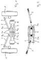
- Fig. 1 shows a schematic representation of a first embodiment of the steer-by-wire steering system according to the invention, wherein steerable wheels 1 via steering lever 3 and tie rods 2 by a carriage 4, which is movably or displaceably mounted on two guide rods 5, adjusted ,
- the carriage 4 forms together with the guide rods 5 four working spaces A 11 , A 12 , A 21 and A 22nd
- the guide rods 5 are rigidly mounted between two valve blocks 6 on the body of the vehicle.
- the carriage 4 and the guide rods 5 form a special piston-cylinder system in which the kinematics is reversed, since here the piston or the guide rod (s) is fixed and moves the cylinder or carriage.
- FIG. 2 shows a further embodiment of the invention Steer-by-wire steering, at which the force application points 2a of the tie rods 2 in the middle between the two guide rods 5 are arranged on the carriage 4. Due to the central arrangement of the force application points 2a to the guide rods 5 results in a low-torque load of the slide 4, whereby the execution is not so must be designed massive.
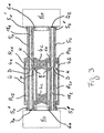
- Fig. 3 shows a cross-sectional view of the piston-cylinder system according to the embodiment of Fig. 2.
- the guide rods 5 1 and 5 2 are mounted between the valve blocks 6 1 and 6 2 .
- the carriage 4 consists of two cylinders 4a and 4b, which are rigidly connected to one another via intermediate parts 4c.
- the guide rods 5 1 and 5 2 are arranged between the valve blocks 6 1 and 6 2 .
- the free ends 5 '1 and 5 "1, 5' 2 and 5 '' 2 are fastened by means of fastening elements 6a to the valve blocks 6 1 and 6 2, bolted in particular with their ends in the valve blocks.
- the guide rods 5 1 and 5 2 are However, it is also possible to choose any cross-sectional shape, but it should be noted that a possible simple and permanent seal between the guide rods and the carriage must be ensured. by choosing a circular cross-section, it is possible that the cavity of each cylinder 4a, 4b, for example, be produced by means of a hole or however formed by a simple tube. the guide rods 5 1 and 5 2 also have continuous cavities. the cavities can However, it is also possible to use a pipe as a guide rod the.
- each guide rod 5 1 , 5 2 engages each of an end face of an inner tube 18 1 , 18 second
- the end 5 " 1 and 5" 2 of each guide rod 5 1 , 5 2 is closed by means of a seal D 1 and D 2 , so that the through the inner tube 18 1 and 18 2 via the guide rod 5 1 and 5 2 in the respective working space A 12 and A 22 flowing medium can not escape from the guide rod 5 1 or 5 2 or the piston-cylinder system.
- the inner tubes 18 1 and 18 2 are each embraced by a seal D at its befindlichem in the cavity end, which seals the inner tube 18 1 and 18 2 relative to the inner wall of the guide rod 5 1 and 5 2 and thus the interior of the Guide rod 5 1 or 5 2 divided into two subregions.
- the guide rod has window-like openings 7, 8, 9 and 10, which connects the supply and discharge lines with the work spaces A 11 , A 12 , A 21 and A 22 .
- a pressure can be built up either in the working space A 11 or in the working space A 22 . So it is within the meaning of the invention to apply both cylinders simultaneously with a fluid pressure. It is also within the meaning of the invention, and this also applies to all illustrated embodiments, that the cylinder 4a together with the guide rod 5 1 part of a first steering circuit and the cylinder 4b together with the guide rod 5 2 part of a second steering circuit. As already explained, both steering circuits can be operated in parallel. However, it is also possible that the first steering circuit is provided for the normal driving operation and dimensioned according to its force level forth, the second steering circuit is switched only supportive to the first steering circuit, for example during parking or Rangier ceremoniess. If the first steering circuit fails, the second steering circuit forms a fallback, whereby the vehicle is still safely steerable.
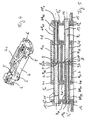
- FIG. 4 shows a perspective view of a steering system according to the invention with two guide rods 5 arranged in parallel, on which two cylinders, which are rigidly connected to one another via intermediate parts 4c, are arranged, which together form a carriage 4.
- the guide rods 5 are arranged between two valve blocks 6.
- the valve blocks 6 correspond to the valve blocks 6 1 and 6 2 shown schematically in FIG. 3.
- the guide rods 5 are formed as tubes, which are held by means of fastening elements 15, 16 parallel to each other.
- the free ends 5 " 1 , 5" 2 are closed by means of screw plugs 12, 14 and seals 11, 13, so that no fluid medium can escape at these ends.
- the screw plugs 12 and 14, respectively, urge the guide rods 5 1 and 5 2 with their free ends 5 ' 1 , 5' 2 into the respective cylinder block. This results in a secure and permanent connection between the guide rods with their channels and the Ventilblökken.
- the fluid medium is conveyed through the opposite free ends of the guide rods 5 1 and 5 2 in the channels formed by the guide rods 5 1 and 5 2 KA 11 and KA 21 in the direction of the working spaces A 11 and A 21 and let out of these.
- the channels KA 11 and KA 21 are formed by the inner wall of the guide rod 5 1 and 5 2 and the inner tube 18 1 and 18 2 , respectively.
- the channels KA 11 and KA 21 are via window-like openings 8, 9 with the associated working spaces A 11 and A 21 in combination.
- the channels KA 12 and KA 22 are formed by the inner tubes 18 1 and 18 2 .
- the channels KA 11 and KA 12 or KA 21 and KA 22 are respectively by a seal D, which includes the end portion of the inner tube 18 1 and 18 2 and abuts against the outer wall and at the same time on the inner wall of the guide rod 5 1 and 5 2 is sealed.
- a seal D which includes the end portion of the inner tube 18 1 and 18 2 and abuts against the outer wall and at the same time on the inner wall of the guide rod 5 1 and 5 2 is sealed.
- a seal D which includes the end portion of the inner tube 18 1 and 18 2 and abuts against the outer wall and at the same time on the inner wall of the guide rod 5 1 and 5 2 is sealed.
- a seal D which includes the end portion of the inner tube 18 1 and 18 2 and abuts against the outer wall and at the same time on the inner wall of the guide rod 5 1 and 5 2 is sealed.
- window-like openings 7, 10 the channels KA 12 and KA 22 with the associated work spaces A 12 and A 22 are connected.
- the ratio between the inner diameter R i of the guide rods 5 1 and 5 2 and the outer diameter R A of the inner tubes 18 1 and 18 2 is to be dimensioned so that the flow cross-sections are approximately equal, or adapted for the respective requirements .
- the cylinders 4 abut with their end portions 4e, 4f on the outside of the guide rod 5 1 and 5 2 , so that no fluid medium can get out of the work spaces out into the environment.
- the work spaces A 11 and A 12 and A 21 and A 22 of the first and second steering circuit are each separated by an annular part K, which may be formed on the outside of the guide rod 5 1 and 5 2 , in particular, collar-shaped.
- stop elements S are provided.
- the stop elements S can in particular be inserted or screwed into a window-like opening or bore of the guide rods 5 1 or 5 2 .
- Fig. 6 shows an alternative embodiment of a two-circuit steer-by-wire steering system according to the invention, only one steered wheel 20 is shown which is about a tie rod 21, which over the joint 21a hinged to a central guide rod 26 is, can be deflected.
- the middle guide rod 26 is rigidly connected to a carriage 23, which in turn mounted slidably on a guide rod 24 is.
- the guide rod 24 is between two valve blocks 25 stored, which with the chassis 22 of the Vehicle are connected.
- the middle tie rod 26 is displaceable parallel to the guide rod 24 via plain bearings 27 mounted on the chassis 22. Due to the elongated design of the carriage 23 is the diameter ago smaller guide rod 24 relatively rigid, so that the Attachment points of the guide rod 24 relatively far outside and thus be placed directly on the chassis 22 can.
- Fig. 7 shows the piston-cylinder system according to the embodiment of Fig. 6 in cross-section.
- the guide rod 24 lies with its two ends in two valve blocks 40, wherein the fluid medium can flow into the channels KA 11 , KA 12 , KA 21 and KA 22 via the valve blocks 40 and can flow out of these.
- Two inner tubes 28 1 and 28 2 engage in each case from one end face of the tube 24 into this and lie with their ends engaging in the tube 24 to stop elements 31, 32 at.
- the free ends of the inner tubes 28 1 and 28 2 are surrounded by annular seals 35, 36 which sealingly abut the outer wall of the inner tubes 28 1 , 28 2 and the inner wall of the tube 24. These seals separate the channels of each steering circuit from each other.
- the channels KA 12 and KA 22 are sealingly separated from each other by a gasket 39 inserted in the pipe 24.
- the guide rod or tube 24 has window-like openings 33, 34, 41 and 42, through which the channels KA 11 , KA 12 , KA 21 and KA 22 with the working spaces A 11 , A 12 , A 21 and A 22 are connected ,
- the displaceably mounted cylinder or slide 25 engages around the guide rod or the pipe 24 and forms together with this the work spaces.
- the end faces of the cylinder 25 are closed by means of seals 38, so that no fluid medium from the working spaces A 11 and A 21 can reach the environment.
- the working spaces A 12 and A 22 are separated by means of a collar 25 located on the collar 25 a and associated seal 37.
- the work spaces A 11 and A 12 are separated by an annular or or collar-shaped part 29 and associated seal.
- the part 29 can be pushed onto the pipe 24 for mounting from the front side and then connected captively to the pipe 24.
- this collar-shaped part can be formed on the tube 24.
- the working spaces A 21 and A 22 are separated from each other by means of a separating element 30 and associated seal.
- the partition members 29, 30 are immovably fixed to the tube 24, whereas the partition wall 25a is displaced with the cylinder 25.
- the cylinders forming parts not in one piece, for example from a Tube or cylinder made, but in two parts or are designed in several parts. So it is possible, for example, to form the cylinder by means of two half-shells, then to provide seals between the two parts are.
- the respective steering circuits can be designed as desired. It is of course possible from the concrete to deviate described embodiments, and yet to make use of the idea of the invention. So can one Guide rod also formed two or more parts if this is necessary for easier assembly is. The individual, a guide rod forming parts can then be plugged together or with each other bolted or otherwise attached or connected become. The same applies to the cylinders forming parts and the sled as a whole.
Landscapes
- Engineering & Computer Science (AREA)
- Mechanical Engineering (AREA)
- Physics & Mathematics (AREA)
- Fluid Mechanics (AREA)
- General Engineering & Computer Science (AREA)
- Chemical & Material Sciences (AREA)
- Combustion & Propulsion (AREA)
- Transportation (AREA)
- Power Steering Mechanism (AREA)
- Steering Control In Accordance With Driving Conditions (AREA)
- Steering-Linkage Mechanisms And Four-Wheel Steering (AREA)
- Actuator (AREA)
Claims (28)
- Direction de commande à orientation par câble comportant un module de réglage qui agit sur les roues orientables (1,20) et travaille d'une manière hydraulique, dans laquelle le module de réglage comporte au moins un coulisseau (4,23), qui est monté de manière à être déplaçable sur une barre de guidage (5,24) qui traverse notamment le coulisseau respectif (4,23), le coulisseau respectif (4,23) forme, conjointement avec la au moins une barre de guidage associée (5,24), des chambres de travail (A11,A12,A21,A22) d'un système à piston et cylindre, la au moins une barre de guidage (5,24) comporte respectivement au moins un canal (KA11, KA12, KA21, KA22), qui se terme respectivement dans la zone d'une chambre de travail (A11, A12, A21, A22) et que le au moins un coulisseau (4,23) règle directement ou à l'aide de barres d'accouplement (2,21), les roues orientables (1,2), caractérisée en ce que la barre de guidage (5,24) est un tube, un premier canal (KA11,KA21) étant formé dans le tube lui-même, et que dans le canal est disposé un tube intérieur (181,182;281,282), dont le diamètre extérieur est inférieur au diamètre intérieur du canal (KA11, KA21) et que le tube intérieur (181,182;281, 282) forme un second canal (KA21,KA22).
- Direction de commande à orientation par câble selon la revendication 1, caractérisée en ce que plusieurs coulisseaux (4a,4b) sont reliés entre eux rigidement directement ou par l'intermédiaire d'un élément intercalaire (4c) et forment un coulisseau.
- Direction de commande à orientation par câble selon la revendication 1 ou 2, caractérisée en ce qu'une barre de guidage (5,24) comporte plusieurs canaux, qui s'étendent à partir de l'une ou les deux faces ou zones frontales de la barre de guidage (5,24), dans cette dernière.
- Direction de commande à orientation par câble selon l'une des revendications précédentes, caractérisée en ce que la au moins une barre de guidage (5,24) est fixée ou montée sur la carrosserie directement ou par l'intermédiaire d'éléments intercalaires sur la carrosserie (22).
- Direction de commande à orientation par câble selon la revendication 1, caractérisée en ce que la au moins une barre de guidage (5,24) est disposée entre deux blocs de soupapes (6;61,62) et que les canaux ou les canalisations d'amenée de la barre de guidage coopèrent activement avec les soupapes d'au moins un bloc de soupapes (61, 62).
- Direction de commande à orientation par câble selon l'une des revendications précédentes, caractérisée en ce qu'une barre de guidage (51,52), qui forme conjointement avec un coulisseau (4;4a,4b), des chambres de travail (A11, A12,A21,A22), comporte au moins un collet (K) dirigé vers l'extérieur, qui notamment est formé par moulage, un collet (K) séparant l'une de l'autre respectivement deux chambres de travail (A11,A12;A21,A22).
- Direction de commande à orientation par câble selon l'une des revendications précédentes, caractérisée en ce que deux barres de guidage (51,52) sont disposées parallèlement entre elles entre deux blocs de soupapes (61, 62) et traversent un coulisseau (4a,4b), et que les canaux respectifs (KA11,KA12,KA21,KA22) des deux barres de guidage (51,52) coopèrent activement respectivement avec uniquement un bloc de soupapes (61,62), le coulisseau (4;4a,4b) formant, avec chaque barre de guidage (51,52), les chambres de travail (A11,A12,A21,A22) d'un système à piston et cylindre et que chaque barre de guidage (51,52) forme, conjointement avec les chambres de travail (A11,A12,A21,A22), qu'elle définit, et le bloc de soupapes associé (61,62), un circuit de direction séparé.
- Direction à orientation par câble selon la revendication 7, caractérisée en ce que respectivement une barre de guidage (51, 52) est entourée par un cylindre (4a, 4b), dont les faces frontales (4e,4f) s'appliquent respectivement de façon étanche contre la barre de guidage associée (51,52), les deux cylindres (4a,4b) étant reliés directement entre eux directement ou par l'intermédiaire d'au moins un élément de liaison (4c) et formant le coulisseau (4).
- Direction à orientation par câble selon la revendication 7 ou 8, caractérisée en ce que les points d'application de force ou les points de support des barres d'accouplement (2) sont disposés entre les deux barres de guidage (51,52), notamment en une position médiane par rapport à ces barres.
- Direction à orientation par câble selon la revendication 7 ou 9, caractérisée en ce que les points d'application de force ou les points de support des barres d'accouplement (2) sont disposés à côté des deux barres de guidage (51, 52).
- Direction à orientation par câble selon l'une des revendications 7 à 10, caractérisée en ce que la barre de guidage est un tube possédant un diamètre intérieur (Ri), qui forme un premier canal (KA11,KA21) et à l'intérieur duquel est disposé un tube intérieur (181,182) possédant un diamètre intérieur (Ra), qui forme un second canal (KA12, KA22), les deux canaux coopérant activement avec le même bloc de soupapes, et qu'une garniture d'étanchéité (D) entoure de façon étanche l'enveloppe cylindrique du tube intérieur (181,182) au niveau de son extrémité libre et s'applique d'une manière étanche contre la paroi intérieure de la paroi de canal (KA11, KA21) de la barre de guidage (51, 52).
- Direction à orientation par câble selon la revendication 11, caractérisée en ce que la garniture d'étanchéité (D) sépare l'un de l'autre les premier et second canaux (KA11, KA12; KA21,KA22) et divise l'espace intérieur de la barre de guidage (51,52) en deux zones.
- Direction à orientation par câble selon la revendication 12, caractérisée en ce que dans la paroi de la barre de guidage (51,52) est disposée respectivement au moins une ouverture en forme de fenêtre (7,8,9,10), qui relie respectivement une zone à une chambre de travail (A11, A12, A21, A22).
- Direction à orientation par câble selon la revendication 12 ou 13, caractérisée en ce que la barre de guidage (51,52) possède, dans la zone de la garniture d'étanchéité (D), un appendice saillant périphérique en forme de collet (K), qui sépare l'une de l'autre les chambres de travail (A11,A12;A21,A22).
- Direction à orientation par câble selon l'une des revendications précédentes 1 à 6, caractérisée en ce qu'une barre de guidage formée par un tube extérieur (24) traverse le coulisseau (23,25), et dans laquelle dans le tube extérieur (24) sont insérés deux tubes intérieurs (281, 282), qui s'étendent respectivement à partir d'une face frontale dans le tube extérieur (24), une garniture d'étanchéité (39) divise l'espace intérieur du tube extérieur (24) en deux chambres partielles séparées l'une de l'autre, et respectivement une bague annulaire d'étanchéité (35,36), qui est située entre le tube intérieur (281,282) et le tube extérieur (24), réalise une séparation étanche entre les deux canaux (KA11,KA12;KA21,KA22) formés par le tube extérieur (24) et le tube intérieur (281,282), et le tube extérieur (24) comporte des ouvertures en forme de fenêtres (33,34), qui relient les canaux (KA11,KA12;KA21,KA22) aux chambres de travail (A11,A12;A21,A22) formées par le tube extérieur (24) et le coulisseau (23,25).
- Direction à orientation par câble selon la revendication 15, caractérisée en ce que le chariot (23) possède une partie de forme tubulaire (25), qui est entourée par le tube extérieur (24) et que les garnitures d'étanchéité (38) situées entre la partie (25) et le tube extérieur (24) ferment de façon étanche les chambres de travail (A11,A21) vis-à-vis de l'extérieur.
- Direction à orientation par câble selon la revendication 15 ou 16, caractérisée en ce qu'un collet (29,30), dirigé vers l'extérieur, qui est situé sur le tube extérieur (25), sépare l'une de l'autre respectivement une chambre de travail (A11,A12;A21,A22) d'un circuit de direction.
- Direction à orientation par câble selon la revendication 17, caractérisée en ce que le collet (29,30) est formé par moulage sur le tube extérieur (24) ou est formé par une partie supplémentaire de forme annulaire, reliée au tube extérieur (24).
- Direction à orientation par câble selon l'une des revendications 15 à 18, caractérisée en ce qu'un collet (25a), qui est dirigé vers l'intérieur et est situé sur la partie de forme tubulaire (25), et une garniture d'étanchéité annulaire (37) séparent réciproquement les deux chambres de travail voisines (A12,A22) de deux circuits de direction.
- Direction à orientation par câble selon l'une des revendications précédentes, caractérisée en ce que les barres d'accouplement (2,21) sont montées de façon à pouvoir tourner respectivement par une de leurs extrémités sur le coulisseau (4,23).
- Direction à orientation par câble selon l'une des revendications précédentes, caractérisée en ce qu'une barre d'accouplement médiane (26) est disposée parallèlement au coulisseau (23) et est fixée sur ce dernier ou y est intégrée, la barre d'accouplement médiane (26) étant montée de manière à être translatable sur la carrosserie (22) parallèlement au coulisseau (23) et que les barres d'accouplement (24) sont montées de manière à pouvoir pivoter ou basculer respectivement par une de leurs extrémités sur la troisième barre d'attelage médiane (26).
- Direction à orientation par câble selon l'une des revendications précédentes, caractérisée en ce que les deux circuits de direction agissent parallèlement simultanément et notamment la soupape associée de commande sont des soupapes à "centre ouvert " ("open center") ou "à centre fermé" ("closed center").
- Direction à orientation par câble selon l'une des revendications 1 à 21, caractérisée en ce que le premier circuit de direction est dimensionné en ce qui concerne son niveau de force, de telle sorte qu'à l'exception de l'opération de parcage ou de l'opération de rangement du véhicule orienté par braquage, ce circuit de direction applique des forces suffisamment intenses pour l'opération de conduite.
- Direction à orientation par câble selon l'une des revendications précédentes 1 à 23, caractérisée en ce que le second circuit de direction assume sa fonction lors de la défaillance du premier circuit de direction.
- Direction à orientation par câble selon la revendication 24, caractérisée en ce que la soupape de commande du premier circuit de direction est une soupape à centre ouvert ("open center") et la soupape de commande du second circuit de direction est une soupape à centre fermé ("closed center").
- Direction à orientation par câble selon l'une des revendications précédentes 22 à 25, caractérisée en ce que le second circuit de direction est dimensionné avec un niveau de force égal ou inférieur à celui du premier circuit de direction.
- Direction à orientation par câble selon l'une des revendications précédentes, caractérisée en ce que la direction comporte des guides supplémentaires pour le support du au moins un coulisseau.
- Direction à orientation par câble selon l'une des revendications précédentes, caractérisée en ce qu'au moins un guide supplémentaire est une barre de guidage, qui traverse le coulisseau.
Applications Claiming Priority (3)
| Application Number | Priority Date | Filing Date | Title |
|---|---|---|---|
| DE10160764A DE10160764A1 (de) | 2001-12-11 | 2001-12-11 | Zweikreisiges Steer-by-wire-Lenksystem mit gemeinsamen Schlitten |
| DE10160764 | 2001-12-11 | ||
| PCT/EP2002/013726 WO2003053765A1 (fr) | 2001-12-11 | 2002-12-04 | Dispositif d'orientation par cables a deux circuits a coulisseaux communs |
Publications (2)
| Publication Number | Publication Date |
|---|---|
| EP1453720A1 EP1453720A1 (fr) | 2004-09-08 |
| EP1453720B1 true EP1453720B1 (fr) | 2005-03-16 |
Family
ID=7708768
Family Applications (1)
| Application Number | Title | Priority Date | Filing Date |
|---|---|---|---|
| EP02805303A Expired - Lifetime EP1453720B1 (fr) | 2001-12-11 | 2002-12-04 | Dispositif d'orientation par cables a deux circuits a coulisseaux communs |
Country Status (6)
| Country | Link |
|---|---|
| US (1) | US7331419B2 (fr) |
| EP (1) | EP1453720B1 (fr) |
| AT (1) | ATE290974T1 (fr) |
| BR (1) | BR0214833B1 (fr) |
| DE (2) | DE10160764A1 (fr) |
| WO (1) | WO2003053765A1 (fr) |
Families Citing this family (9)
| Publication number | Priority date | Publication date | Assignee | Title |
|---|---|---|---|---|
| DE10304520A1 (de) * | 2003-02-04 | 2004-09-02 | Thyssenkrupp Presta Steertec Gmbh | Lenkung |
| US8201656B2 (en) * | 2007-10-04 | 2012-06-19 | Oshkosh Corporation | Vehicle steering system |
| DE102007053322A1 (de) * | 2007-11-08 | 2009-05-20 | Agco Gmbh | Lenkungsvorrichtung für ein Nutzfahrzeug |
| EP2209695B1 (fr) * | 2007-11-08 | 2012-05-23 | AGCO GmbH | Système de direction pour véhicule utilitaire |
| GB2464728A (en) * | 2008-10-27 | 2010-04-28 | Agco Gmbh | Hydraulic steering device with redundancy |
| DE102013203188A1 (de) * | 2013-02-26 | 2014-08-28 | Bayerische Motoren Werke Aktiengesellschaft | Lenkaktuator-Anordnung zwischen den Hinterrädern eines zweispurigen Fahrzeugs |
| US10822026B2 (en) | 2018-07-30 | 2020-11-03 | Deere & Company | Dual steering cylinder system |
| CN109162982B (zh) * | 2018-10-21 | 2020-01-03 | 佛山市工芯精密机械有限公司 | 一种无活塞的双作用缸体装置 |
| DE102023000067B4 (de) | 2023-01-12 | 2024-11-07 | Mercedes-Benz Group AG | Lenksystem für ein Fahrzeug |
Family Cites Families (15)
| Publication number | Priority date | Publication date | Assignee | Title |
|---|---|---|---|---|
| FR1101290A (fr) * | 1954-03-19 | 1955-10-04 | Rech S Etudes | Servo-commande applicable notamment à la direction des véhicules automobiles et autres |
| US2930631A (en) * | 1957-11-13 | 1960-03-29 | Firestone Tire & Rubber Co | Trailer steering mechanism |
| CH412625A (de) | 1962-12-07 | 1966-04-30 | Kiekert Friedrich Wilhelm | Doppeltwirkender Zylinder-Kolbenantrieb an einer Schwenkschiebetür eines Fahrzeugs |
| JPS5920773A (ja) | 1982-07-26 | 1984-02-02 | Nissan Motor Co Ltd | 車両における操舵用パワ−シリンダの取付け構造 |
| US4568292A (en) * | 1983-12-05 | 1986-02-04 | Outboard Marine Corporation | Hydraulic assistance device for use in a steering system |
| JPH0631078B2 (ja) * | 1985-05-17 | 1994-04-27 | 三信工業株式会社 | 船舶推進機の操舵装置 |
| CA1283581C (fr) * | 1989-01-19 | 1991-04-30 | Martin Rump | Mecanisme de gouverne pour dispositif propulseur de bateau |
| US5471907A (en) * | 1992-01-03 | 1995-12-05 | Kobelt Manufacturing Co. Ltd. | Marine steering apparatus |
| GB2275662A (en) | 1993-03-02 | 1994-09-07 | Gloster Saro Ltd | Vehicle steering systems |
| JP3918162B2 (ja) * | 1997-11-28 | 2007-05-23 | 株式会社 神崎高級工機製作所 | 車輌用パワーステアリング装置 |
| DE19918354A1 (de) | 1999-04-22 | 2000-10-26 | Volkswagen Ag | Hydraulisches Stellteil zur Betätigung der Lenkung von Kraftfahrzeugen |
| ITSV20030027A1 (it) * | 2003-06-17 | 2004-12-18 | Ultraflex Spa | Dispositivo di sterzatura in particolare per motori nautici fuoribordo. |
| US7147525B2 (en) * | 2004-01-26 | 2006-12-12 | Marol Co., Ltd. | Hydraulic steering apparatus for an outboard engine |
| US7025168B2 (en) * | 2004-04-16 | 2006-04-11 | Deere & Company | Steering cylinder shield |
| US7150664B1 (en) * | 2005-12-08 | 2006-12-19 | Brunswick Corporation | Steering actuator for an outboard motor |
-
2001
- 2001-12-11 DE DE10160764A patent/DE10160764A1/de not_active Withdrawn
-
2002
- 2002-12-04 AT AT02805303T patent/ATE290974T1/de not_active IP Right Cessation
- 2002-12-04 BR BRPI0214833-1A patent/BR0214833B1/pt not_active IP Right Cessation
- 2002-12-04 EP EP02805303A patent/EP1453720B1/fr not_active Expired - Lifetime
- 2002-12-04 DE DE50202511T patent/DE50202511D1/de not_active Expired - Lifetime
- 2002-12-04 US US10/498,619 patent/US7331419B2/en not_active Expired - Fee Related
- 2002-12-04 WO PCT/EP2002/013726 patent/WO2003053765A1/fr not_active Ceased
Also Published As
| Publication number | Publication date |
|---|---|
| BR0214833A (pt) | 2004-12-14 |
| WO2003053765A1 (fr) | 2003-07-03 |
| EP1453720A1 (fr) | 2004-09-08 |
| US7331419B2 (en) | 2008-02-19 |
| ATE290974T1 (de) | 2005-04-15 |
| DE10160764A1 (de) | 2003-07-03 |
| BR0214833B1 (pt) | 2011-07-26 |
| US20050103559A1 (en) | 2005-05-19 |
| DE50202511D1 (de) | 2005-04-21 |
Similar Documents
| Publication | Publication Date | Title |
|---|---|---|
| DE69931859T2 (de) | Fahrzeugaufhängungsvorrichtung | |
| EP0806587B1 (fr) | Unité piston-cyclindre avec caractéristiques d'amortissement variables en fonction de la distance | |
| EP1651502B1 (fr) | Mecanisme de direction pour automobile | |
| EP0756552B1 (fr) | Systeme de direction a essieux multiples pour vehicules | |
| DE2127187C3 (de) | Steuervorrichtung für eine hydraulische Hilfskraftlenkung | |
| EP3253645B1 (fr) | Stabilisation de direction | |
| EP0710774A2 (fr) | Verin de travail | |
| DE19603568A1 (de) | Lenkung für Kraftfahrzeuge | |
| EP1529717B1 (fr) | Dispositif de blocage pour direction hydraulique d'un essieu arrière de véhicule | |
| EP2272736A1 (fr) | Axe directeur pour remorque | |
| DE10160764A1 (de) | Zweikreisiges Steer-by-wire-Lenksystem mit gemeinsamen Schlitten | |
| DE3902810A1 (de) | Mehrachslenkanlage | |
| EP0949094A2 (fr) | Stabilisateur pour véhicules automobiles | |
| DE202005014926U1 (de) | Stabilisator-Baugruppe für ein Kraftfahrzeug | |
| DE3837777A1 (de) | Hydraulische getriebeschaltung | |
| DE19815314A1 (de) | Hydraulisch betätigter Drehsteller | |
| DE2628017C3 (de) | Hydraulische Hilfskraftlenkeinrichtung für Fahrzeuge | |
| EP3758962B1 (fr) | Système amortisseur à ressort à constante de rappel pouvant être commutée de façon immédiate | |
| DE3836103C2 (fr) | ||
| DE3426204A1 (de) | Hydraulisches lenksystem fuer kraftfahrzeuge | |
| DE9415009U1 (de) | Radaufhängungssystem für zweispurige Fahrzeuge | |
| DE102004040940A1 (de) | Baugruppe für ein Fahrwerkstabilisierungssystem | |
| DE3108529C2 (de) | Lenkgestänge für Kraftfahrzeuge, insbesondere Personenkraftwagen | |
| EP0307612A1 (fr) | Direction assistée pour véhicules | |
| DE102007053322A1 (de) | Lenkungsvorrichtung für ein Nutzfahrzeug |
Legal Events
| Date | Code | Title | Description |
|---|---|---|---|
| PUAI | Public reference made under article 153(3) epc to a published international application that has entered the european phase |
Free format text: ORIGINAL CODE: 0009012 |
|
| 17P | Request for examination filed |
Effective date: 20040316 |
|
| AK | Designated contracting states |
Kind code of ref document: A1 Designated state(s): AT BE BG CH CY CZ DE DK EE ES FI FR GB GR IE IT LI LU MC NL PT SE SI SK TR |
|
| GRAP | Despatch of communication of intention to grant a patent |
Free format text: ORIGINAL CODE: EPIDOSNIGR1 |
|
| GRAS | Grant fee paid |
Free format text: ORIGINAL CODE: EPIDOSNIGR3 |
|
| GRAA | (expected) grant |
Free format text: ORIGINAL CODE: 0009210 |
|
| AK | Designated contracting states |
Kind code of ref document: B1 Designated state(s): AT BE BG CH CY CZ DE DK EE ES FI FR GB GR IE IT LI LU MC NL PT SE SI SK TR |
|
| PG25 | Lapsed in a contracting state [announced via postgrant information from national office to epo] |
Ref country code: SK Free format text: LAPSE BECAUSE OF FAILURE TO SUBMIT A TRANSLATION OF THE DESCRIPTION OR TO PAY THE FEE WITHIN THE PRESCRIBED TIME-LIMIT Effective date: 20050316 Ref country code: CZ Free format text: LAPSE BECAUSE OF FAILURE TO SUBMIT A TRANSLATION OF THE DESCRIPTION OR TO PAY THE FEE WITHIN THE PRESCRIBED TIME-LIMIT Effective date: 20050316 Ref country code: NL Free format text: LAPSE BECAUSE OF FAILURE TO SUBMIT A TRANSLATION OF THE DESCRIPTION OR TO PAY THE FEE WITHIN THE PRESCRIBED TIME-LIMIT Effective date: 20050316 Ref country code: FI Free format text: LAPSE BECAUSE OF FAILURE TO SUBMIT A TRANSLATION OF THE DESCRIPTION OR TO PAY THE FEE WITHIN THE PRESCRIBED TIME-LIMIT Effective date: 20050316 Ref country code: SI Free format text: LAPSE BECAUSE OF FAILURE TO SUBMIT A TRANSLATION OF THE DESCRIPTION OR TO PAY THE FEE WITHIN THE PRESCRIBED TIME-LIMIT Effective date: 20050316 Ref country code: IE Free format text: LAPSE BECAUSE OF FAILURE TO SUBMIT A TRANSLATION OF THE DESCRIPTION OR TO PAY THE FEE WITHIN THE PRESCRIBED TIME-LIMIT Effective date: 20050316 Ref country code: EE Free format text: LAPSE BECAUSE OF FAILURE TO SUBMIT A TRANSLATION OF THE DESCRIPTION OR TO PAY THE FEE WITHIN THE PRESCRIBED TIME-LIMIT Effective date: 20050316 |
|
| REG | Reference to a national code |
Ref country code: GB Ref legal event code: FG4D Free format text: NOT ENGLISH |
|
| REG | Reference to a national code |
Ref country code: CH Ref legal event code: EP |
|
| GBT | Gb: translation of ep patent filed (gb section 77(6)(a)/1977) |
Effective date: 20050316 |
|
| REG | Reference to a national code |
Ref country code: IE Ref legal event code: FG4D Free format text: GERMAN |
|
| REF | Corresponds to: |
Ref document number: 50202511 Country of ref document: DE Date of ref document: 20050421 Kind code of ref document: P |
|
| REG | Reference to a national code |
Ref country code: SE Ref legal event code: TRGR |
|
| PG25 | Lapsed in a contracting state [announced via postgrant information from national office to epo] |
Ref country code: GR Free format text: LAPSE BECAUSE OF FAILURE TO SUBMIT A TRANSLATION OF THE DESCRIPTION OR TO PAY THE FEE WITHIN THE PRESCRIBED TIME-LIMIT Effective date: 20050616 Ref country code: BG Free format text: LAPSE BECAUSE OF FAILURE TO SUBMIT A TRANSLATION OF THE DESCRIPTION OR TO PAY THE FEE WITHIN THE PRESCRIBED TIME-LIMIT Effective date: 20050616 Ref country code: DK Free format text: LAPSE BECAUSE OF FAILURE TO SUBMIT A TRANSLATION OF THE DESCRIPTION OR TO PAY THE FEE WITHIN THE PRESCRIBED TIME-LIMIT Effective date: 20050616 |
|
| PG25 | Lapsed in a contracting state [announced via postgrant information from national office to epo] |
Ref country code: ES Free format text: LAPSE BECAUSE OF FAILURE TO SUBMIT A TRANSLATION OF THE DESCRIPTION OR TO PAY THE FEE WITHIN THE PRESCRIBED TIME-LIMIT Effective date: 20050627 |
|
| NLV1 | Nl: lapsed or annulled due to failure to fulfill the requirements of art. 29p and 29m of the patents act | ||
| PG25 | Lapsed in a contracting state [announced via postgrant information from national office to epo] |
Ref country code: PT Free format text: LAPSE BECAUSE OF FAILURE TO SUBMIT A TRANSLATION OF THE DESCRIPTION OR TO PAY THE FEE WITHIN THE PRESCRIBED TIME-LIMIT Effective date: 20050907 |
|
| REG | Reference to a national code |
Ref country code: IE Ref legal event code: FD4D |
|
| PG25 | Lapsed in a contracting state [announced via postgrant information from national office to epo] |
Ref country code: CY Free format text: LAPSE BECAUSE OF FAILURE TO SUBMIT A TRANSLATION OF THE DESCRIPTION OR TO PAY THE FEE WITHIN THE PRESCRIBED TIME-LIMIT Effective date: 20051204 Ref country code: AT Free format text: LAPSE BECAUSE OF NON-PAYMENT OF DUE FEES Effective date: 20051204 |
|
| PG25 | Lapsed in a contracting state [announced via postgrant information from national office to epo] |
Ref country code: BE Free format text: LAPSE BECAUSE OF NON-PAYMENT OF DUE FEES Effective date: 20051231 Ref country code: MC Free format text: LAPSE BECAUSE OF NON-PAYMENT OF DUE FEES Effective date: 20051231 Ref country code: LU Free format text: LAPSE BECAUSE OF NON-PAYMENT OF DUE FEES Effective date: 20051231 |
|
| PLBE | No opposition filed within time limit |
Free format text: ORIGINAL CODE: 0009261 |
|
| STAA | Information on the status of an ep patent application or granted ep patent |
Free format text: STATUS: NO OPPOSITION FILED WITHIN TIME LIMIT |
|
| ET | Fr: translation filed | ||
| 26N | No opposition filed |
Effective date: 20051219 |
|
| PG25 | Lapsed in a contracting state [announced via postgrant information from national office to epo] |
Ref country code: LI Free format text: LAPSE BECAUSE OF NON-PAYMENT OF DUE FEES Effective date: 20061231 Ref country code: CH Free format text: LAPSE BECAUSE OF NON-PAYMENT OF DUE FEES Effective date: 20061231 |
|
| REG | Reference to a national code |
Ref country code: CH Ref legal event code: PL |
|
| BERE | Be: lapsed |
Owner name: THYSSENKRUPP PRESTA STEERTEC G.M.B.H. Effective date: 20051231 |
|
| PGFP | Annual fee paid to national office [announced via postgrant information from national office to epo] |
Ref country code: GB Payment date: 20121220 Year of fee payment: 11 Ref country code: TR Payment date: 20121127 Year of fee payment: 11 Ref country code: IT Payment date: 20121221 Year of fee payment: 11 Ref country code: SE Payment date: 20121220 Year of fee payment: 11 |
|
| PGFP | Annual fee paid to national office [announced via postgrant information from national office to epo] |
Ref country code: DE Payment date: 20121218 Year of fee payment: 11 Ref country code: FR Payment date: 20130117 Year of fee payment: 11 |
|
| REG | Reference to a national code |
Ref country code: DE Ref legal event code: R119 Ref document number: 50202511 Country of ref document: DE |
|
| REG | Reference to a national code |
Ref country code: SE Ref legal event code: EUG |
|
| GBPC | Gb: european patent ceased through non-payment of renewal fee |
Effective date: 20131204 |
|
| PG25 | Lapsed in a contracting state [announced via postgrant information from national office to epo] |
Ref country code: SE Free format text: LAPSE BECAUSE OF NON-PAYMENT OF DUE FEES Effective date: 20131205 |
|
| REG | Reference to a national code |
Ref country code: FR Ref legal event code: ST Effective date: 20140829 |
|
| REG | Reference to a national code |
Ref country code: DE Ref legal event code: R119 Ref document number: 50202511 Country of ref document: DE Effective date: 20140701 |
|
| PG25 | Lapsed in a contracting state [announced via postgrant information from national office to epo] |
Ref country code: DE Free format text: LAPSE BECAUSE OF NON-PAYMENT OF DUE FEES Effective date: 20140701 |
|
| PG25 | Lapsed in a contracting state [announced via postgrant information from national office to epo] |
Ref country code: FR Free format text: LAPSE BECAUSE OF NON-PAYMENT OF DUE FEES Effective date: 20131231 Ref country code: GB Free format text: LAPSE BECAUSE OF NON-PAYMENT OF DUE FEES Effective date: 20131204 |
|
| PG25 | Lapsed in a contracting state [announced via postgrant information from national office to epo] |
Ref country code: IT Free format text: LAPSE BECAUSE OF NON-PAYMENT OF DUE FEES Effective date: 20131231 |
|
| PG25 | Lapsed in a contracting state [announced via postgrant information from national office to epo] |
Ref country code: TR Free format text: LAPSE BECAUSE OF NON-PAYMENT OF DUE FEES Effective date: 20131204 |
|
| PG25 | Lapsed in a contracting state [announced via postgrant information from national office to epo] |
Ref country code: IT Free format text: LAPSE BECAUSE OF NON-PAYMENT OF DUE FEES Effective date: 20131204 |