EP0806595B1 - Electrovanne - Google Patents
Electrovanne Download PDFInfo
- Publication number
- EP0806595B1 EP0806595B1 EP19970101174 EP97101174A EP0806595B1 EP 0806595 B1 EP0806595 B1 EP 0806595B1 EP 19970101174 EP19970101174 EP 19970101174 EP 97101174 A EP97101174 A EP 97101174A EP 0806595 B1 EP0806595 B1 EP 0806595B1
- Authority
- EP
- European Patent Office
- Prior art keywords
- valve
- valve seat
- chamber
- spring
- valve plate
- Prior art date
- Legal status (The legal status is an assumption and is not a legal conclusion. Google has not performed a legal analysis and makes no representation as to the accuracy of the status listed.)
- Expired - Lifetime
Links
- 238000002485 combustion reaction Methods 0.000 claims description 5
- 230000005415 magnetization Effects 0.000 claims description 2
- 230000005284 excitation Effects 0.000 claims 1
- 238000009423 ventilation Methods 0.000 description 4
- 230000006378 damage Effects 0.000 description 2
- 239000002828 fuel tank Substances 0.000 description 2
- 238000011109 contamination Methods 0.000 description 1
- 238000011161 development Methods 0.000 description 1
- 230000018109 developmental process Effects 0.000 description 1
- 230000005281 excited state Effects 0.000 description 1
Images
Classifications
-
- F—MECHANICAL ENGINEERING; LIGHTING; HEATING; WEAPONS; BLASTING
- F16—ENGINEERING ELEMENTS AND UNITS; GENERAL MEASURES FOR PRODUCING AND MAINTAINING EFFECTIVE FUNCTIONING OF MACHINES OR INSTALLATIONS; THERMAL INSULATION IN GENERAL
- F16K—VALVES; TAPS; COCKS; ACTUATING-FLOATS; DEVICES FOR VENTING OR AERATING
- F16K31/00—Actuating devices; Operating means; Releasing devices
- F16K31/02—Actuating devices; Operating means; Releasing devices electric; magnetic
- F16K31/06—Actuating devices; Operating means; Releasing devices electric; magnetic using a magnet, e.g. diaphragm valves, cutting off by means of a liquid
- F16K31/0644—One-way valve
- F16K31/0655—Lift valves
-
- F—MECHANICAL ENGINEERING; LIGHTING; HEATING; WEAPONS; BLASTING
- F02—COMBUSTION ENGINES; HOT-GAS OR COMBUSTION-PRODUCT ENGINE PLANTS
- F02M—SUPPLYING COMBUSTION ENGINES IN GENERAL WITH COMBUSTIBLE MIXTURES OR CONSTITUENTS THEREOF
- F02M25/00—Engine-pertinent apparatus for adding non-fuel substances or small quantities of secondary fuel to combustion-air, main fuel or fuel-air mixture
- F02M25/08—Engine-pertinent apparatus for adding non-fuel substances or small quantities of secondary fuel to combustion-air, main fuel or fuel-air mixture adding fuel vapours drawn from engine fuel reservoir
- F02M25/0836—Arrangement of valves controlling the admission of fuel vapour to an engine, e.g. valve being disposed between fuel tank or absorption canister and intake manifold
-
- Y—GENERAL TAGGING OF NEW TECHNOLOGICAL DEVELOPMENTS; GENERAL TAGGING OF CROSS-SECTIONAL TECHNOLOGIES SPANNING OVER SEVERAL SECTIONS OF THE IPC; TECHNICAL SUBJECTS COVERED BY FORMER USPC CROSS-REFERENCE ART COLLECTIONS [XRACs] AND DIGESTS
- Y10—TECHNICAL SUBJECTS COVERED BY FORMER USPC
- Y10T—TECHNICAL SUBJECTS COVERED BY FORMER US CLASSIFICATION
- Y10T137/00—Fluid handling
- Y10T137/7722—Line condition change responsive valves
- Y10T137/7771—Bi-directional flow valves
- Y10T137/7778—Axes of ports perpendicular
-
- Y—GENERAL TAGGING OF NEW TECHNOLOGICAL DEVELOPMENTS; GENERAL TAGGING OF CROSS-SECTIONAL TECHNOLOGIES SPANNING OVER SEVERAL SECTIONS OF THE IPC; TECHNICAL SUBJECTS COVERED BY FORMER USPC CROSS-REFERENCE ART COLLECTIONS [XRACs] AND DIGESTS
- Y10—TECHNICAL SUBJECTS COVERED BY FORMER USPC
- Y10T—TECHNICAL SUBJECTS COVERED BY FORMER US CLASSIFICATION
- Y10T137/00—Fluid handling
- Y10T137/7722—Line condition change responsive valves
- Y10T137/7771—Bi-directional flow valves
- Y10T137/7779—Axes of ports parallel
-
- Y—GENERAL TAGGING OF NEW TECHNOLOGICAL DEVELOPMENTS; GENERAL TAGGING OF CROSS-SECTIONAL TECHNOLOGIES SPANNING OVER SEVERAL SECTIONS OF THE IPC; TECHNICAL SUBJECTS COVERED BY FORMER USPC CROSS-REFERENCE ART COLLECTIONS [XRACs] AND DIGESTS
- Y10—TECHNICAL SUBJECTS COVERED BY FORMER USPC
- Y10T—TECHNICAL SUBJECTS COVERED BY FORMER US CLASSIFICATION
- Y10T137/00—Fluid handling
- Y10T137/7722—Line condition change responsive valves
- Y10T137/7837—Direct response valves [i.e., check valve type]
- Y10T137/7897—Vacuum relief type
-
- Y—GENERAL TAGGING OF NEW TECHNOLOGICAL DEVELOPMENTS; GENERAL TAGGING OF CROSS-SECTIONAL TECHNOLOGIES SPANNING OVER SEVERAL SECTIONS OF THE IPC; TECHNICAL SUBJECTS COVERED BY FORMER USPC CROSS-REFERENCE ART COLLECTIONS [XRACs] AND DIGESTS
- Y10—TECHNICAL SUBJECTS COVERED BY FORMER USPC
- Y10T—TECHNICAL SUBJECTS COVERED BY FORMER US CLASSIFICATION
- Y10T137/00—Fluid handling
- Y10T137/7722—Line condition change responsive valves
- Y10T137/7837—Direct response valves [i.e., check valve type]
- Y10T137/7904—Reciprocating valves
- Y10T137/7908—Weight biased
- Y10T137/7909—Valve body is the weight
- Y10T137/7913—Guided head
- Y10T137/7914—Cage
Definitions
- the invention relates to an electromagnetic switching valve, in particular for an application in internal combustion engines, according to the preamble of claim 1.
- switching valves are used for various switching functions, for Example is from DE-A1 41 40 255 a switching valve in a ventilation device for known a fuel tank of an internal combustion engine, which has a ventilation line to the atmosphere controls.
- the lockable ventilation line allows targeted lower and lower To be able to set overpressures in the system, thereby increasing its functionality check.
- valve closing part in the excited state Magnetic circuit moving position is only so strong that above one predetermined overpressure, the pressure force generated thereby is sufficient, the valve closing part to move to the open position.
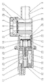
- the drawing shows a section through an electrical switching valve 1 according to the invention, for example for a ventilation device of a fuel tank of an internal combustion engine can be used.
- This consists of a coil housing 2 and one Valve housing 3, the valve housing 3 a connecting piece 4 for the to be controlled Medium, which via a valve seat 5 into an atmospheric ventilated chamber 6 and leads into the atmosphere 9 via a bypass duct 7 with a suction valve 8.
- the coil housing 2 has a coil body 10 with contact lugs 11 and an anchor yoke 12.
- An armature core 14 and a bearing section 15 for a magnet armature 16 are arranged in a central bore 13, the armature core 14 having a through opening 17 which leads into the atmospherically ventilated chamber 6 of the valve housing 3.
- valve seat 5 of the valve housing 3 with a Valve plate 18 cooperates, which is clamped in an intermediate basket 19 and through a spring 20 is loaded against axial stops 21 of the intermediate basket 19, the intermediate basket 19 mounted radially and axially within the chamber 6 and under the force of a Spring 22 is loaded against a magnet armature 16 and by this in magnetization Direction of the valve seat 5 can be adjusted so that the valve plate 18 against the Valve seat 5 comes to rest and from the axial stops 21 of the intermediate basket 19 takes off.
- the intermediate basket 19 is made of a round base plate 23 formed, which has a plurality of ribs 24 on one side, which the axial stops 21st have and the spring 20 loading the valve plate 18, and on the other side has a rod extension 25 which projects through the passage opening 17 and below the force of between a wall 26 of the chamber 6 and the outer edge of the base plate 23 clamped spring 22 is loaded against the magnet armature 16.
- valve seat bushing 28 As can be seen from the drawing, the outlet section of the valve seat bushing 28 is through a cover 31 pushed onto the valve housing 3 is protected against contamination.
- valve plates 18, 29 and springs 20 and 30 are matched in terms of area and force are achieved, that the valve plates at the same predetermined Lift the pressure difference off the valve seats.
- This pressure difference can be achieved by the large valve plates arranged in a space-saving manner very easy to set with little copy scatter.
Landscapes
- Engineering & Computer Science (AREA)
- General Engineering & Computer Science (AREA)
- Mechanical Engineering (AREA)
- Chemical & Material Sciences (AREA)
- Combustion & Propulsion (AREA)
- Magnetically Actuated Valves (AREA)
- Safety Valves (AREA)
Claims (2)
- Électrovanne de commande (1), en particulier pour utilisation sur un moteur à combustion interne, constituée d'une boíte à bobine (2) et d'une boíte à soupapes (3), la boíte à soupapes (3) présentant une tubulure de raccordement (4) pour le fluide à commander, laquelle mène par un siège de soupape (5) dans une chambre (6) communiquant avec l'atmosphère et, par un conduit de dérivation (7) pourvu d'une soupape d'aspiration (8), dans l'atmosphère, le siège de soupape (5) coopérant avec un plateau de soupape (18) qui est monté dans un panier intermédiaire (19), et le panier intermédiaire (19) étant appuyé radialement et axialement à l'intérieur de la chambre (6) et chargé sous la force d'un ressort (22) contre une armature d'aimant (16) et pouvant, en cas d'aimantation, être déplacé par celle-ci en direction du siège de soupape (5), de sorte que le plateau de soupape (18) vient s'appuyer contre le siège de soupape (5), caractérisée par le fait que le plateau de soupape (18) est chargé par un ressort (20) contre des butées axiales (21) du panier intermédiaire (19), et que lors de l'excitation de l'armature d'aimant (16), le plateau de soupape (18) s'écarte des butées axiales (21) du panier intermédiaire (19).
- Électrovanne de commande selon la revendication 1, caractérisée par le fait qu'entre la tubulure de raccordement (4) et le conduit de dérivation (7) existe une chambre à soupape d'aspiration (27) qui est limitée vers l'atmosphère par une douille de siège de soupape (28) qui présente le conduit de dérivation (7), la douille de siège de soupape (28) coopérant avec un plateau de soupape (29) de la soupape d'aspiration (8) qui est chargé par un ressort (30) disposé à l'intérieur de la chambre à soupape (27).
Applications Claiming Priority (2)
| Application Number | Priority Date | Filing Date | Title |
|---|---|---|---|
| DE19619196 | 1996-05-11 | ||
| DE1996119196 DE19619196A1 (de) | 1996-05-11 | 1996-05-11 | Elektromagnetisches Schaltventil |
Publications (2)
| Publication Number | Publication Date |
|---|---|
| EP0806595A1 EP0806595A1 (fr) | 1997-11-12 |
| EP0806595B1 true EP0806595B1 (fr) | 2001-06-13 |
Family
ID=7794149
Family Applications (1)
| Application Number | Title | Priority Date | Filing Date |
|---|---|---|---|
| EP19970101174 Expired - Lifetime EP0806595B1 (fr) | 1996-05-11 | 1997-01-24 | Electrovanne |
Country Status (5)
| Country | Link |
|---|---|
| US (1) | US5853162A (fr) |
| EP (1) | EP0806595B1 (fr) |
| KR (1) | KR100436349B1 (fr) |
| DE (2) | DE19619196A1 (fr) |
| ES (1) | ES2157490T3 (fr) |
Families Citing this family (12)
| Publication number | Priority date | Publication date | Assignee | Title |
|---|---|---|---|---|
| DE19619196A1 (de) * | 1996-05-11 | 1997-11-13 | Pierburg Ag | Elektromagnetisches Schaltventil |
| US6016690A (en) * | 1997-09-05 | 2000-01-25 | Siemens Canada Limited | Automotive evaporative emission leak detection system and method |
| US6053151A (en) * | 1997-09-08 | 2000-04-25 | Siemens Canada Limited | Automotive evaporative emission leak detection system and module |
| USD467871S1 (en) | 2000-06-07 | 2002-12-31 | Sanden Corporation | Electrical connector housing for an electromagnetic control valve |
| DE10213696C1 (de) * | 2002-03-27 | 2003-10-30 | Pierburg Gmbh | Elektromagnetische Stellvorrichtung |
| ITFI20050169A1 (it) * | 2005-07-27 | 2007-01-28 | Saeco Ipr Ltd | Circuito idraulico per macchine da bevande espresso, valvola di scarico e sicurezza per detto circuito e relativo metodo per produzione di bevande espresso |
| AU2009295960A1 (en) | 2008-09-29 | 2010-04-01 | Cardiaq Valve Technologies, Inc. | Heart valve |
| EP2341871B1 (fr) | 2008-10-01 | 2017-03-22 | Edwards Lifesciences CardiAQ LLC | Système de mise en place pour implant vasculaire |
| EP4119098A1 (fr) | 2009-04-15 | 2023-01-18 | Edwards Lifesciences CardiAQ LLC | Implant vasculaire et système de distribution |
| US9730790B2 (en) | 2009-09-29 | 2017-08-15 | Edwards Lifesciences Cardiaq Llc | Replacement valve and method |
| DE102010055316B4 (de) * | 2010-12-21 | 2016-09-08 | Audi Ag | Einrichtung zur Entlüftung und Belüftung eines Kraftstofftanks |
| CN113915031B (zh) * | 2021-10-18 | 2022-06-17 | 苏州恩都法汽车系统有限公司 | 油箱隔离阀控制系统 |
Family Cites Families (13)
| Publication number | Priority date | Publication date | Assignee | Title |
|---|---|---|---|---|
| US1423679A (en) * | 1922-02-04 | 1922-07-25 | Pavitchich Steve | Drain valve |
| US3473780A (en) * | 1967-05-11 | 1969-10-21 | Honeywell Inc | Control apparatus |
| US3800793A (en) * | 1971-12-23 | 1974-04-02 | R Marrese | Anesthesia apparatus having negative pressure relief means |
| DE2740646C2 (de) * | 1977-09-09 | 1982-05-19 | Bürkert GmbH, 7118 Ingelfingen | Elektromagnetisch direkt gesteuertes Sicherheitsabsperrventil |
| DE3008002A1 (de) * | 1980-03-01 | 1981-09-10 | Reutter GmbH Metallwarenfabrik, 7050 Waiblingen | Verschlussdeckel insbesondere fuer einen kraftfahrzeugkuehler |
| CH665264A5 (fr) * | 1985-03-18 | 1988-04-29 | Honeywell Lucifer Sa | Electrovalve a plusieurs debits. |
| US4674529A (en) * | 1986-05-14 | 1987-06-23 | Ferguson Sean M | Check valve |
| JPH01109681U (fr) * | 1988-01-20 | 1989-07-25 | ||
| JPH0814855B2 (ja) * | 1988-10-20 | 1996-02-14 | 富士通株式会社 | 蛋白質表示処理方法 |
| US5048560A (en) * | 1989-12-12 | 1991-09-17 | L&J Engineering Inc. | Sealing valve assembly |
| DE4140255C3 (de) | 1991-12-06 | 1999-05-20 | Bosch Gmbh Robert | Entlüftungsvorrichtung für einen Brennstofftank einer Brennkraftmaschine |
| DE4409033C2 (de) | 1994-03-17 | 1999-05-27 | Pierburg Ag | Elektromagnetisches Schaltventil |
| DE19619196A1 (de) * | 1996-05-11 | 1997-11-13 | Pierburg Ag | Elektromagnetisches Schaltventil |
-
1996
- 1996-05-11 DE DE1996119196 patent/DE19619196A1/de not_active Withdrawn
-
1997
- 1997-01-24 ES ES97101174T patent/ES2157490T3/es not_active Expired - Lifetime
- 1997-01-24 EP EP19970101174 patent/EP0806595B1/fr not_active Expired - Lifetime
- 1997-01-24 DE DE59703757T patent/DE59703757D1/de not_active Expired - Fee Related
- 1997-05-02 KR KR1019970017017A patent/KR100436349B1/ko not_active Expired - Fee Related
- 1997-05-06 US US08/852,267 patent/US5853162A/en not_active Expired - Fee Related
Also Published As
| Publication number | Publication date |
|---|---|
| US5853162A (en) | 1998-12-29 |
| KR970075617A (ko) | 1997-12-10 |
| DE19619196A1 (de) | 1997-11-13 |
| EP0806595A1 (fr) | 1997-11-12 |
| KR100436349B1 (ko) | 2004-09-20 |
| MX9703295A (es) | 1997-11-29 |
| DE59703757D1 (de) | 2001-07-19 |
| ES2157490T3 (es) | 2001-08-16 |
Similar Documents
| Publication | Publication Date | Title |
|---|---|---|
| EP0806595B1 (fr) | Electrovanne | |
| DE60023824T2 (de) | Elektromagnetisches Dosierventil für ein Kraftstoffeinspritzventil | |
| DE102009012688B3 (de) | Ventil zum Einblasen von Gas | |
| EP1062420A1 (fr) | Vanne pour l'admission dosee d'un carburant volatil | |
| EP0816732B1 (fr) | Soupape électromagnétique | |
| DE19751609B4 (de) | Schmalbauender elektromagnetischer Aktuator | |
| DE3312067A1 (de) | Elektromagnetisch betaetigbares ventil | |
| WO2017215842A1 (fr) | Électrovanne à double induit et procédé de fonctionnement | |
| DE112013005438T5 (de) | Solenoid-Ventilplatte | |
| EP0699859B1 (fr) | Electrovanne de commande | |
| DE4439695C2 (de) | Magnetventil und dessen Verwendung | |
| DE19740580C2 (de) | Elektromagnetisches Schaltventil | |
| EP1456570B1 (fr) | Soupape dotee d'un element d'amortissement | |
| WO2001057389A2 (fr) | Soupape d'injection electromagnetique pour reguler une quantite de carburant destinee a alimenter un moteur a combustion interne | |
| DE3810826A1 (de) | Elektromagnetisches einspritzventil fuer brennkraftmaschinen | |
| WO2001007775A1 (fr) | Soupape pour introduire de maniere dosee du carburant volatil dans le canal d'aspiration d'un moteur a combustion interne | |
| DE102007049945A1 (de) | Brennstoffeinspritzventil | |
| DE3444452A1 (de) | Elektromagnetisch betaetigbares kraftstoffeinspritzventil | |
| DE4409033C2 (de) | Elektromagnetisches Schaltventil | |
| DE102021209468A1 (de) | Magnetventil sowie Wasserstofftanksystem mit Magnetventil | |
| EP0314878A2 (fr) | Méthode pour ajuster la longueur du ressort en état comprimé de la soupape de recirculation de gaz d'échappement pour un moteur à combustion interne | |
| DE3876770T2 (de) | Elektromagnetisches brennstoffeinspritzventil. | |
| DE3437162A1 (de) | Elektromagnetisch betaetigbares kraftstoffeinspritzventil | |
| DE69302540T2 (de) | Verbessertes elektromagnetisches Kraftstoffdosier- und Kraftstoffzerstäubungsventil | |
| DE1031073B (de) | Ventil fuer Schaltungen íÀAuf und ZuíÂmit einer elastischen Ventilverschlussscheibe |
Legal Events
| Date | Code | Title | Description |
|---|---|---|---|
| PUAI | Public reference made under article 153(3) epc to a published international application that has entered the european phase |
Free format text: ORIGINAL CODE: 0009012 |
|
| 17P | Request for examination filed |
Effective date: 19970125 |
|
| AK | Designated contracting states |
Kind code of ref document: A1 Designated state(s): DE ES FR GB IT |
|
| 17Q | First examination report despatched |
Effective date: 19990803 |
|
| GRAG | Despatch of communication of intention to grant |
Free format text: ORIGINAL CODE: EPIDOS AGRA |
|
| GRAG | Despatch of communication of intention to grant |
Free format text: ORIGINAL CODE: EPIDOS AGRA |
|
| GRAH | Despatch of communication of intention to grant a patent |
Free format text: ORIGINAL CODE: EPIDOS IGRA |
|
| GRAH | Despatch of communication of intention to grant a patent |
Free format text: ORIGINAL CODE: EPIDOS IGRA |
|
| GRAA | (expected) grant |
Free format text: ORIGINAL CODE: 0009210 |
|
| ITF | It: translation for a ep patent filed | ||
| AK | Designated contracting states |
Kind code of ref document: B1 Designated state(s): DE ES FR GB IT |
|
| REF | Corresponds to: |
Ref document number: 59703757 Country of ref document: DE Date of ref document: 20010719 |
|
| REG | Reference to a national code |
Ref country code: ES Ref legal event code: FG2A Ref document number: 2157490 Country of ref document: ES Kind code of ref document: T3 |
|
| ET | Fr: translation filed | ||
| GBT | Gb: translation of ep patent filed (gb section 77(6)(a)/1977) |
Effective date: 20010906 |
|
| REG | Reference to a national code |
Ref country code: GB Ref legal event code: IF02 |
|
| PLBE | No opposition filed within time limit |
Free format text: ORIGINAL CODE: 0009261 |
|
| STAA | Information on the status of an ep patent application or granted ep patent |
Free format text: STATUS: NO OPPOSITION FILED WITHIN TIME LIMIT |
|
| 26N | No opposition filed | ||
| REG | Reference to a national code |
Ref country code: FR Ref legal event code: CJ |
|
| PGFP | Annual fee paid to national office [announced via postgrant information from national office to epo] |
Ref country code: GB Payment date: 20040105 Year of fee payment: 8 |
|
| PGFP | Annual fee paid to national office [announced via postgrant information from national office to epo] |
Ref country code: DE Payment date: 20040108 Year of fee payment: 8 |
|
| PGFP | Annual fee paid to national office [announced via postgrant information from national office to epo] |
Ref country code: FR Payment date: 20040109 Year of fee payment: 8 |
|
| PGFP | Annual fee paid to national office [announced via postgrant information from national office to epo] |
Ref country code: ES Payment date: 20040122 Year of fee payment: 8 |
|
| PG25 | Lapsed in a contracting state [announced via postgrant information from national office to epo] |
Ref country code: IT Free format text: LAPSE BECAUSE OF NON-PAYMENT OF DUE FEES Effective date: 20050124 Ref country code: GB Free format text: LAPSE BECAUSE OF NON-PAYMENT OF DUE FEES Effective date: 20050124 |
|
| PG25 | Lapsed in a contracting state [announced via postgrant information from national office to epo] |
Ref country code: ES Free format text: LAPSE BECAUSE OF NON-PAYMENT OF DUE FEES Effective date: 20050125 |
|
| PG25 | Lapsed in a contracting state [announced via postgrant information from national office to epo] |
Ref country code: DE Free format text: LAPSE BECAUSE OF NON-PAYMENT OF DUE FEES Effective date: 20050802 |
|
| GBPC | Gb: european patent ceased through non-payment of renewal fee |
Effective date: 20050124 |
|
| PG25 | Lapsed in a contracting state [announced via postgrant information from national office to epo] |
Ref country code: FR Free format text: LAPSE BECAUSE OF NON-PAYMENT OF DUE FEES Effective date: 20050930 |
|
| REG | Reference to a national code |
Ref country code: FR Ref legal event code: ST |
|
| REG | Reference to a national code |
Ref country code: ES Ref legal event code: FD2A Effective date: 20050125 |