EP0806615A2 - Entlüftungsanordnung für Gebäude - Google Patents
Entlüftungsanordnung für Gebäude Download PDFInfo
- Publication number
- EP0806615A2 EP0806615A2 EP97303067A EP97303067A EP0806615A2 EP 0806615 A2 EP0806615 A2 EP 0806615A2 EP 97303067 A EP97303067 A EP 97303067A EP 97303067 A EP97303067 A EP 97303067A EP 0806615 A2 EP0806615 A2 EP 0806615A2
- Authority
- EP
- European Patent Office
- Prior art keywords
- air
- air supply
- air exhaust
- path
- buildings
- Prior art date
- Legal status (The legal status is an assumption and is not a legal conclusion. Google has not performed a legal analysis and makes no representation as to the accuracy of the status listed.)
- Granted
Links
- 238000005273 aeration Methods 0.000 title claims abstract description 36
- XLYOFNOQVPJJNP-UHFFFAOYSA-N water Substances O XLYOFNOQVPJJNP-UHFFFAOYSA-N 0.000 claims description 24
- 238000009423 ventilation Methods 0.000 description 7
- 239000007789 gas Substances 0.000 description 4
- 239000002826 coolant Substances 0.000 description 3
- 239000000779 smoke Substances 0.000 description 2
- 238000000638 solvent extraction Methods 0.000 description 2
- RYGMFSIKBFXOCR-UHFFFAOYSA-N Copper Chemical compound [Cu] RYGMFSIKBFXOCR-UHFFFAOYSA-N 0.000 description 1
- 206010021143 Hypoxia Diseases 0.000 description 1
- 230000036760 body temperature Effects 0.000 description 1
- 238000002485 combustion reaction Methods 0.000 description 1
- 238000010276 construction Methods 0.000 description 1
- 238000001816 cooling Methods 0.000 description 1
- 229910052802 copper Inorganic materials 0.000 description 1
- 239000010949 copper Substances 0.000 description 1
- 230000005611 electricity Effects 0.000 description 1
- 238000005265 energy consumption Methods 0.000 description 1
- 231100001261 hazardous Toxicity 0.000 description 1
- 238000010438 heat treatment Methods 0.000 description 1
- 230000002093 peripheral effect Effects 0.000 description 1
- 238000010792 warming Methods 0.000 description 1
Images


Classifications
-
- E—FIXED CONSTRUCTIONS
- E04—BUILDING
- E04B—GENERAL BUILDING CONSTRUCTIONS; WALLS, e.g. PARTITIONS; ROOFS; FLOORS; CEILINGS; INSULATION OR OTHER PROTECTION OF BUILDINGS
- E04B1/00—Constructions in general; Structures which are not restricted either to walls, e.g. partitions, or floors or ceilings or roofs
- E04B1/62—Insulation or other protection; Elements or use of specified material therefor
- E04B1/70—Drying or keeping dry, e.g. by air vents
- E04B1/7069—Drying or keeping dry, e.g. by air vents by ventilating
- E04B1/7076—Air vents for walls
-
- F—MECHANICAL ENGINEERING; LIGHTING; HEATING; WEAPONS; BLASTING
- F24—HEATING; RANGES; VENTILATING
- F24F—AIR-CONDITIONING; AIR-HUMIDIFICATION; VENTILATION; USE OF AIR CURRENTS FOR SCREENING
- F24F7/00—Ventilation
- F24F7/04—Ventilation with ducting systems, e.g. by double walls; with natural circulation
- F24F7/06—Ventilation with ducting systems, e.g. by double walls; with natural circulation with forced air circulation, e.g. by fan positioning of a ventilator in or against a conduit
Definitions
- the present invention relates to aeration structures in buildings, and more specifically but not exclusively to aeration structures for making use of natural aeration based on heat generated in a living room space.
- the living room 1 shown in Fig. 1 is located in a horizontal section 6 of the U-shaped aeration path shown in Fig. 2 and the air supply hole 2 is opened in the side of the vertical path 4 with the air exhaust hole 3 opened in the side of the vertical path 5.
- heat is generated inside the living chamber 1, so that an air flow is generated by which air in the vertical path 4 flows through the air supply hole 2 into the living room 2 and the heated air is then exhausted through the air exhaust hole 3 into the vertical path 5.
- the inventor of the present invention has paid special attention to generation of natural draft pressure due to generation of heat inside a living room as described above.
- the present invention provides an aeration structure for buildings, wherein an air supply hole is provided in a lower section of a living room and an air exhaust hole is provided in an upper section of the living room
- the present invention provides an aeration structure for plural story buildings having a living room on each floor, wherein an air supply hole for inletting outdoor air is provided in a lower section of each living room and an air exhaust hole is provided in an upper section of each living room, and an air supply path and an air exhaust path communicate with said air supply hole and said air exhaust hole in each living room respectively, said air supply path and said air exhaust path each extending in the vertical direction.
- the aeration structure is for multistorey buildings.
- the air supply path and air exhaust path are formed outside a frame of a building.
- the air supply path and air exhaust path are provided inside a frame of a building and the paths extend through each of the living rooms on each floor.
- an air exhaust fan is provided at an exit section of the air exhaust path.
- the air supply path and the air exhaust path are provided by partitioning a double shaft (for example a double cylinder) comprising an internal shaft and an external shaft.
- a double shaft for example a double cylinder
- a span member is provided between the external shaft and each node of the building frame.
- a structural support shaft (for example a cylinder) is arranged around the external periphery of the external shaft, a span member is provided between the structural support shaft and a node of the building frame, and piping, e.g. for equipment, is accommodated in a space between the external shaft and the structural support shaft.
- a water gathering section for gathering rain water is formed in a roof portion of the building frame with the internal and external shafts projecting into the water gathering section, and a rain water pipe open in the water gathering section is accommodated in the air exhaust path.
- a building 10 comprises concrete construction based on a multi-storied structure with living rooms 11 in each floor.
- An air supply hole 12 is provided in a lower section of each living room, and an air exhaust hole 13 is provided at a height difference H above the air supply hole 12 in an upper section of each living room.
- the air supply hole 12 and air exhaust hole 13 are provided on opposite walls.
- a supply shaft 14, contacting an external surface, and an air exhaust shaft 15, contacting an external surface on the opposite side, are provided outside a frame 10a of the building 10.
- Both the air supply shaft 14 and air exhaust shaft 15 which have a rectangular cross section and are made from concrete have an air supply path 16 and an air exhaust path 17 formed therein.
- the air supply path 16 and air exhaust path 17 are communicated to the air supply hole 12 and the air exhaust hole 13 respectively in each living room 11 on each floor.
- a relation between a cross-sectional area F0 of the air supply path 16 and a cross-sectional area F1 of the air exhaust path 17 is expressed by the expression F1 ⁇ F0 (The relation is applicable in each of the embodiments described below).
- the reference numeral 10b indicates a water drain.
- Fig. 5 shows a second preferred embodiment of the present invention, and in this embodiment, the air supply shaft 14 and air exhaust shaft 15 are provided in parallel to each other on the same external surface of the frame 10a.
- Fig. 6 shows a third preferred embodiment of the present invention, and in this embodiment, the air supply shaft (internal one) 14 and air exhaust shaft (external one) 15 together constituting a double shaft extend through each living room 11 on each floor.
- the air exhaust path 17 is provided between the air supply shaft 14 and air exhaust shaft 15.
- the air exhaust hole 13 is provided in the air exhaust shaft 15 and the air supply hole 12 and air supply path 16 are communicated to each other by a piping 22 which passes through the air exhaust shaft 15.
- the air supply shaft 14 and air exhaust shaft 15 which together constitute a double shaft may be provided outside the frame 10a as in the first embodiment.
- Fig. 7 shows a fourth preferred embodiment of the present invention, and in this embodiment, the air supply shaft 14 and air exhaust shaft 15, each having a rectangular cross section and being made from concrete, extend through the two living rooms adjoining each other, the shafts occupying a portion of each of the living rooms 11, in each floor, and the air supply path 16 and air exhaust path 17 being shared by the two adjoining living rooms.
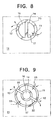
- Fig. 8 shows a fifth preferred embodiment of the present invention, and in this embodiment, an air supply/exhaust shaft in the form of a cylinder 23 having a round cross section extends through the living room 11 in each floor, and the air supply/exhaust cylinder 23 is partitioned by a partitioning body 24 into the air supply path 16 and air exhaust path 17.
- Fig. 9 shows a sixth preferred embodiment of the present invention, and in this embodiment, the air supply cylinder 14 and air exhaust cylinder 15 form a double cylinder having a round cross section, and the air supply cylinder 14 and air exhaust cylinder 15 extend through each living room 11 in each floor.
- a plurality of air supply holes 12 and air exhaust holes 13 are provided in the air exhaust cylinder 15, and the air supply holes 12 and the air supply path are communicated to each other by the piping 22.
- Fig. 10 shows a seventh preferred embodiment of the present invention, and in this embodiment, additional components are added to the sixth embodiment.
- the air supply cylinder 14 and air exhaust cylinder 15 extend through a substantially central portion of the living room, and a span member 28 is provided between the air exhaust cylinder 15 and a node 27 of the frame 10a.
- the span member 28 is made from a turnbuckle, but may be made with concrete.
- the exhaust cylinder 15 and the span member form a monolithic body, and function as a structural support for the building.
- the reference numeral 29 indicates a public corridor and the reference numeral 30 indicates a veranda.
- Fig. 11 indicates an eighth preferred embodiment of the present invention, and in this embodiment, additional components are added to the seventh embodiment. Namely a pipe shaft 31 is provided around the external periphery of the air supply/exhaust cylinders 14,15 having therein the air supply path 16 and air exhaust path 17 so that a triple cylinder is formed as a whole.
- the air supply/exhaust cylinders 14, 15 and the pipe shaft 31 are made from copper.
- the air supply hole 12 and air exhaust hole 13 are provided in the pipe shaft 31, and the air supply hole 12 and the air supply path 16 are communicated to each other by the piping 22.
- a span member 28 is provided between the pipe shaft 31 and a node 27, and the pipe shaft 31 functions as a structural support and also as a space for accommodating therein various types of equipment and piping for the equipment.
- a hot water supplier 34 accommodated in a space 33 formed between the pipe shaft 31 and the air exhaust cylinder 15 are a hot water supplier 34, a cooling medium piping 35 for an air conditioner 35, and piping 37 such as a gas pipe, a water pipe, or a pipe for drainage.
- the hot water supplier 34 is based on a combustion system, the hot water supplier 34 is communicated through a pipe 38 to the air supply path 16.
- Fig. 12 shows a ninth preferred embodiment of the present invention, and in this embodiment, the air supply/exhaust cylinders 14, 15, hot water supplier 34, cooling medium pipe 35, and piping 37 are accommodated in a meter box 42 formed within the living room 11.
- the air supply hole 12 and air supply path 16 are communicated to each other through the pipe 22, and the air exhaust hole 13 and air exhaust path 17 are communicated to each other through the pipe 32.
- the reference numeral 41 indicates an outdoor portion of an air conditioner
- the reference numeral 42 indicates an indoor portion of an air conditioner.
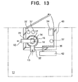
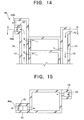
- Fig. 14 and Fig. 15 show a tenth preferred embodiment of the present invention, and in this embodiment, additional components are added to the first embodiment of the present invention.
- An entrance 43 to the air supply path 16 and an exit 44 from the air exhaust path 17 face sidewards, and the exit 44 of the air exhaust path 17 consists of two exits 44a and 44b.
- An air exhaust fan 45 is provided at the exit 44a. Forcible air exhaustion is executed by the air exhaust fan 45, but during a power failure air exhaustion is executed from the other exit 44b.
- Fig. 16 and Fig. 17 show an eleventh preferred embodiment of the present invention, and in this embodiment, a roof surface 50 of the building 10 has a V-shaped form, and a water gathering section 51 is formed at the central portion.
- An aeration cover 53 with aeration openings 52 on the peripheral surface is set at the top of the air supply/exhaust cylinders 14, 15 together constituting a double cylinder.
- the drainage pipe 54 is accommodated in the air exhaust path 17, and an upper edge of this drainage pipe 54 extends through the air exhaust cylinder 15 and is opened in the water gathering section 51. When it rains, rain water is gathered into the water gathering section 51, and flows down through the drainage pipe 54.
- the internal shaft functions as an air supply shaft and the external shaft as an air exhaust shaft, but the internal shaft may function as an air exhaust shaft and the external shaft as an air supply shaft.
- At least the preferred embodiments of the present invention provide: an aeration structure for buildings giving energy savings in relation to aeration and ventilation systems; an aeration structure for buildings in which the aeration or ventilation system does not stop functioning even if the life line goes down in natural disasters; an aeration structure for buildings in which the air paths and components each constituting the same may be used for various purposes; an aeration structure for buildings, allowing the reduction in length of concrete spans, thus simplifying the structure and also allowing an improvement in antiseismic capability of a building.
Landscapes
- Engineering & Computer Science (AREA)
- Chemical & Material Sciences (AREA)
- Combustion & Propulsion (AREA)
- Mechanical Engineering (AREA)
- General Engineering & Computer Science (AREA)
- Architecture (AREA)
- Physics & Mathematics (AREA)
- Electromagnetism (AREA)
- Civil Engineering (AREA)
- Structural Engineering (AREA)
- Building Environments (AREA)
- Ventilation (AREA)
- Duct Arrangements (AREA)
Applications Claiming Priority (3)
| Application Number | Priority Date | Filing Date | Title |
|---|---|---|---|
| JP14063396 | 1996-05-10 | ||
| JP08140633A JP3132807B2 (ja) | 1996-05-10 | 1996-05-10 | 建築物における通気構造 |
| JP140633/96 | 1996-05-10 |
Publications (3)
| Publication Number | Publication Date |
|---|---|
| EP0806615A2 true EP0806615A2 (de) | 1997-11-12 |
| EP0806615A3 EP0806615A3 (de) | 1998-06-03 |
| EP0806615B1 EP0806615B1 (de) | 2002-08-28 |
Family
ID=15273233
Family Applications (1)
| Application Number | Title | Priority Date | Filing Date |
|---|---|---|---|
| EP97303067A Expired - Lifetime EP0806615B1 (de) | 1996-05-10 | 1997-05-06 | Entlüftungsanordnung für Gebäude |
Country Status (10)
| Country | Link |
|---|---|
| US (1) | US5934993A (de) |
| EP (1) | EP0806615B1 (de) |
| JP (1) | JP3132807B2 (de) |
| KR (1) | KR970075141A (de) |
| CN (1) | CN1170123A (de) |
| AU (1) | AU727089B2 (de) |
| BR (1) | BR9703089A (de) |
| CA (1) | CA2204690A1 (de) |
| DE (1) | DE69714904D1 (de) |
| NO (2) | NO308966B1 (de) |
Cited By (5)
| Publication number | Priority date | Publication date | Assignee | Title |
|---|---|---|---|---|
| ES2265200A1 (es) * | 2003-07-11 | 2007-02-01 | Victor Julian Calero Gomez | Sistema de ventilacion y salida de gases conducida. |
| WO2009066189A1 (en) * | 2007-11-23 | 2009-05-28 | Ridas Matonis | Ventilation and air conditioning system for high-rise buildings |
| WO2010052594A1 (en) * | 2008-11-05 | 2010-05-14 | Ridas Matonis | Air ventilation and coditioning system having a function of electric power generation |
| WO2016055995A1 (en) * | 2014-10-07 | 2016-04-14 | Tadiran Group Ltd | Building structure for a multi-story building |
| DE102021105980A1 (de) | 2021-03-11 | 2022-09-15 | Werner Schallenberg | Luftführungseinrichtung zum Lüften und Entlüften eines Raumes gegenüber einer außerhalb des Raumes angeordneten Umgebung sowie Lüftungsanordnung mit einer Luftführungseinrichtung und einer Einrichtung zur kontrollierten Wohnraumlüftung |
Families Citing this family (24)
| Publication number | Priority date | Publication date | Assignee | Title |
|---|---|---|---|---|
| US6675542B1 (en) * | 2002-06-14 | 2004-01-13 | Aaron I. Norton | Housing for an internal combustion engine |
| US7250000B2 (en) * | 2004-09-02 | 2007-07-31 | Daniels Ii William B | Building with improved vent arrangement |
| WO2007038170A1 (en) * | 2005-09-23 | 2007-04-05 | Daniels William B | Passive ventilation control system |
| CN101225988B (zh) * | 2008-01-21 | 2011-04-06 | 西安建筑科技大学 | 竖壁贴附射流空气湖模式通风系统 |
| JP4870124B2 (ja) * | 2008-07-07 | 2012-02-08 | 高砂熱学工業株式会社 | 竪配管施工方法 |
| CN101858629B (zh) * | 2010-06-04 | 2012-08-29 | 杨宗荣 | 室内空气更换器 |
| US8574045B2 (en) * | 2010-12-17 | 2013-11-05 | Dina Warner | Frost-free vent assembly |
| US9163846B2 (en) * | 2011-01-17 | 2015-10-20 | Vkr Holding A/S | Ventilation apparatus arrangements |
| JP5710342B2 (ja) * | 2011-03-31 | 2015-04-30 | 株式会社熊谷組 | 排気装置 |
| CN102505833A (zh) * | 2011-11-21 | 2012-06-20 | 北京建筑工程学院 | 具有显热回收功能的新排风共用建筑通风竖井 |
| JP2013190159A (ja) * | 2012-03-14 | 2013-09-26 | Toda Constr Co Ltd | 建物における自然換気システム |
| AU2015202537B2 (en) * | 2013-04-05 | 2017-08-17 | Siang Teik Teoh | Coaxial ventilator |
| US9739495B2 (en) * | 2013-04-05 | 2017-08-22 | Siang Teik Teoh | Coaxial ventilator |
| MY174077A (en) | 2014-04-04 | 2020-03-09 | Siang Teik Teoh | Coaxial ventilator |
| US10852017B2 (en) * | 2014-11-24 | 2020-12-01 | Sang Ho Shin | Air umbrella device |
| RU2590231C1 (ru) * | 2015-04-24 | 2016-07-10 | Владимир Викторович Дриго | Вентиляционный блок и способ его монтажа |
| US9856631B2 (en) | 2015-09-29 | 2018-01-02 | Tim K. Stanley | Rain catcher with release coupling |
| JP2016178941A (ja) * | 2016-06-16 | 2016-10-13 | ユーテック株式会社 | 水耕栽培装置 |
| CN109529499A (zh) * | 2018-12-28 | 2019-03-29 | 安徽中固建设有限公司 | 一种大型楼宇空气循环系统 |
| CN111023384B (zh) * | 2019-12-28 | 2021-09-10 | 安徽协鼎建设工程有限公司 | 一种用于消防工程的排烟系统 |
| CN111101689A (zh) * | 2020-02-27 | 2020-05-05 | 唐山市正达建筑材料有限公司 | 一种具有进风换气功能的楼房气道及安装使用方法 |
| KR102184739B1 (ko) * | 2020-06-30 | 2020-11-30 | (주)미가존종합건축사사무소 | 건축물 조립식 공동 배기구 |
| KR102650491B1 (ko) * | 2023-03-31 | 2024-03-22 | (주)종합건축사사무소환경건축 | 건축용 조립식 공동 배기구 |
| CN116480098B (zh) * | 2023-04-27 | 2025-08-05 | 中国十七冶集团有限公司 | 沿海建筑人防工程风机房风井隔墙施工方法 |
Family Cites Families (23)
| Publication number | Priority date | Publication date | Assignee | Title |
|---|---|---|---|---|
| US424778A (en) * | 1890-04-01 | William gee | ||
| US20909A (en) * | 1858-07-13 | Territory | ||
| US99722A (en) * | 1870-02-08 | Improved device for ventilating and cooling or warming beds | ||
| US61820A (en) * | 1867-02-05 | Vtwillation | ||
| GB189605014A (en) * | 1896-03-05 | 1897-02-13 | William Heaton | Improvements in Apparatus to be Employed in the Ventilation of Buildings or Enclosed Spaces. |
| US1207855A (en) * | 1916-01-19 | 1916-12-12 | William P Cantwell | Mausoleum. |
| US1689246A (en) * | 1926-01-30 | 1928-10-30 | Knapen Achille | System of vertical differential ventilation |
| US1690905A (en) * | 1926-03-27 | 1928-11-06 | Francis E Mcdevitt | Ventilating system |
| FR725730A (fr) * | 1931-11-05 | 1932-05-17 | Dispositif de ventilation des salles de spectacle ou autres | |
| BE517710A (de) * | 1952-05-19 | |||
| JPS5938538A (ja) * | 1982-08-24 | 1984-03-02 | Matsushita Electric Ind Co Ltd | 換気用壁体 |
| DE3310569A1 (de) * | 1983-03-23 | 1984-09-27 | Robert Dipl.-Ing.(FH) 8000 München Spieldiener | Be- und entlueftungsanlage fuer mehrgeschossige bauwerke |
| JPS6065537U (ja) * | 1984-02-20 | 1985-05-09 | 風巻 秀夫 | 家屋の通気機構 |
| JPS62164523U (de) * | 1986-04-08 | 1987-10-19 | ||
| JPS63165632A (ja) * | 1986-12-25 | 1988-07-08 | ナショナル住宅産業株式会社 | 家屋の通気システム |
| JPS6421142A (en) * | 1987-07-17 | 1989-01-24 | Jgc Corp | Building with natural ventilating device |
| JPH01314833A (ja) * | 1988-06-13 | 1989-12-20 | Shimizu Corp | 中高層ビルにおける室内排気システム |
| FR2691789B1 (fr) * | 1992-05-27 | 1999-04-23 | Michel Zaniewski | Perfectionnements aux dispositifs assurant la repartition et la regulation automatique des debits d'air notamment pour la ventilation des locaux. |
| JP2708679B2 (ja) * | 1992-10-07 | 1998-02-04 | 株式会社奥村組 | 地中建造物 |
| JP2739672B2 (ja) * | 1992-10-28 | 1998-04-15 | 株式会社間組 | 建造物の給排気設備 |
| SE9303002L (sv) * | 1993-09-15 | 1995-03-16 | Otto Andersson | Anordning för montage av ventilationskanaler och filter med filterhållare samt metoder i samband med montage och byte av filter |
| JPH0861727A (ja) * | 1994-08-24 | 1996-03-08 | Fujita Corp | 構造躯体の中空構造部分を利用する換気システム |
| JPH0875210A (ja) * | 1994-08-31 | 1996-03-19 | Keizo Sugiyama | 床下熱利用の冷暖房と換気装置 |
-
1996
- 1996-05-10 JP JP08140633A patent/JP3132807B2/ja not_active Expired - Fee Related
-
1997
- 1997-04-24 KR KR1019970015399A patent/KR970075141A/ko not_active Ceased
- 1997-05-06 EP EP97303067A patent/EP0806615B1/de not_active Expired - Lifetime
- 1997-05-06 DE DE69714904T patent/DE69714904D1/de not_active Expired - Lifetime
- 1997-05-07 US US08/852,398 patent/US5934993A/en not_active Expired - Fee Related
- 1997-05-07 CA CA002204690A patent/CA2204690A1/en not_active Abandoned
- 1997-05-08 BR BR9703089A patent/BR9703089A/pt not_active Application Discontinuation
- 1997-05-09 CN CN97111516A patent/CN1170123A/zh active Pending
- 1997-05-09 NO NO972139A patent/NO308966B1/no not_active IP Right Cessation
- 1997-05-09 AU AU20167/97A patent/AU727089B2/en not_active Ceased
-
2000
- 2000-03-28 NO NO20001591A patent/NO310044B1/no not_active IP Right Cessation
Non-Patent Citations (1)
| Title |
|---|
| None |
Cited By (8)
| Publication number | Priority date | Publication date | Assignee | Title |
|---|---|---|---|---|
| ES2265200A1 (es) * | 2003-07-11 | 2007-02-01 | Victor Julian Calero Gomez | Sistema de ventilacion y salida de gases conducida. |
| ES2265200B1 (es) * | 2003-07-11 | 2008-01-01 | Victor Julian Calero Gomez | Sistema de ventilacion y salida de gases conducida. |
| WO2009066189A1 (en) * | 2007-11-23 | 2009-05-28 | Ridas Matonis | Ventilation and air conditioning system for high-rise buildings |
| WO2010052594A1 (en) * | 2008-11-05 | 2010-05-14 | Ridas Matonis | Air ventilation and coditioning system having a function of electric power generation |
| WO2016055995A1 (en) * | 2014-10-07 | 2016-04-14 | Tadiran Group Ltd | Building structure for a multi-story building |
| CN107109851A (zh) * | 2014-10-07 | 2017-08-29 | 塔迪兰集团有限公司 | 用于多层建筑物的建筑结构 |
| US10551077B2 (en) | 2014-10-07 | 2020-02-04 | Tadiran Group Ltd | Building structure for a multi-story building |
| DE102021105980A1 (de) | 2021-03-11 | 2022-09-15 | Werner Schallenberg | Luftführungseinrichtung zum Lüften und Entlüften eines Raumes gegenüber einer außerhalb des Raumes angeordneten Umgebung sowie Lüftungsanordnung mit einer Luftführungseinrichtung und einer Einrichtung zur kontrollierten Wohnraumlüftung |
Also Published As
| Publication number | Publication date |
|---|---|
| JPH09302792A (ja) | 1997-11-25 |
| NO972139D0 (no) | 1997-05-09 |
| NO308966B1 (no) | 2000-11-20 |
| EP0806615A3 (de) | 1998-06-03 |
| US5934993A (en) | 1999-08-10 |
| NO20001591D0 (no) | 2000-03-28 |
| BR9703089A (pt) | 1998-09-08 |
| JP3132807B2 (ja) | 2001-02-05 |
| AU2016797A (en) | 1997-11-13 |
| CA2204690A1 (en) | 1997-11-10 |
| NO972139L (no) | 1997-11-11 |
| EP0806615B1 (de) | 2002-08-28 |
| KR970075141A (ko) | 1997-12-10 |
| DE69714904D1 (de) | 2002-10-02 |
| AU727089B2 (en) | 2000-11-30 |
| NO310044B1 (no) | 2001-05-07 |
| CN1170123A (zh) | 1998-01-14 |
| NO20001591L (no) | 1997-11-11 |
Similar Documents
| Publication | Publication Date | Title |
|---|---|---|
| EP0806615B1 (de) | Entlüftungsanordnung für Gebäude | |
| Lstiburek et al. | Air pressure and building envelopes | |
| RU2722614C2 (ru) | Система отопления и охлаждения модульного жилого здания | |
| Taylor et al. | Environmental design using dynamic insulation | |
| Ten Wolde et al. | Air pressures in wood frame walls. | |
| JP4026961B2 (ja) | 住宅の換気構造 | |
| WO2013016824A1 (en) | Efficient house: an efficient, healthful and durable building system using differential airflow and heat control across an air permeable heat reflective external envelope assembly | |
| Tooley et al. | Mechanical air distribution and interacting relationships | |
| CN215832095U (zh) | 一种被动式建筑的风口构造 | |
| Field | Breeze blocks. | |
| JP2000355985A (ja) | 建築物における通気構造 | |
| JP3044506B2 (ja) | 逆梁床構造の集合住宅 | |
| CN218292997U (zh) | 一种通过自然排烟减小地下二层层高的地下车库 | |
| CN209874585U (zh) | 一种航改机型分布式能源站分布系统 | |
| JP2013083146A (ja) | ロフト付き建物 | |
| JP2000336890A (ja) | 乾式タイル用下地パネルと乾式タイル用下地パネルの施工方法 | |
| JP3729337B2 (ja) | 建物の自然換気方法とそのための自然換気構造 | |
| RU2078181C1 (ru) | Садовый дом | |
| JP2534512Y2 (ja) | ユニット住宅の屋根ユニット | |
| Handegord | Air leakage, ventilation, and moisture control in buildings | |
| JPH11324351A (ja) | 中廊下式集合住宅 | |
| Tamura et al. | Experimental Fire Tower Studies on Controlling Smoke Movement Caused by | |
| HK40089305A (zh) | 模块化住宅建筑的供暖和冷却系统 | |
| Hunt et al. | Moisture interactions in light-frame housing: a review | |
| JP2025042951A (ja) | 集合住宅 |
Legal Events
| Date | Code | Title | Description |
|---|---|---|---|
| PUAI | Public reference made under article 153(3) epc to a published international application that has entered the european phase |
Free format text: ORIGINAL CODE: 0009012 |
|
| AK | Designated contracting states |
Kind code of ref document: A2 Designated state(s): DE DK FI FR GB NL |
|
| PUAL | Search report despatched |
Free format text: ORIGINAL CODE: 0009013 |
|
| AK | Designated contracting states |
Kind code of ref document: A3 Designated state(s): DE DK FI FR GB NL |
|
| 17P | Request for examination filed |
Effective date: 19980703 |
|
| 17Q | First examination report despatched |
Effective date: 20001212 |
|
| GRAG | Despatch of communication of intention to grant |
Free format text: ORIGINAL CODE: EPIDOS AGRA |
|
| GRAG | Despatch of communication of intention to grant |
Free format text: ORIGINAL CODE: EPIDOS AGRA |
|
| GRAH | Despatch of communication of intention to grant a patent |
Free format text: ORIGINAL CODE: EPIDOS IGRA |
|
| GRAH | Despatch of communication of intention to grant a patent |
Free format text: ORIGINAL CODE: EPIDOS IGRA |
|
| GRAA | (expected) grant |
Free format text: ORIGINAL CODE: 0009210 |
|
| AK | Designated contracting states |
Kind code of ref document: B1 Designated state(s): DE DK FI FR GB NL |
|
| PG25 | Lapsed in a contracting state [announced via postgrant information from national office to epo] |
Ref country code: FR Free format text: LAPSE BECAUSE OF NON-PAYMENT OF DUE FEES Effective date: 20020828 Ref country code: FI Free format text: LAPSE BECAUSE OF FAILURE TO SUBMIT A TRANSLATION OF THE DESCRIPTION OR TO PAY THE FEE WITHIN THE PRESCRIBED TIME-LIMIT Effective date: 20020828 |
|
| REG | Reference to a national code |
Ref country code: GB Ref legal event code: FG4D |
|
| REF | Corresponds to: |
Ref document number: 69714904 Country of ref document: DE Date of ref document: 20021002 |
|
| PG25 | Lapsed in a contracting state [announced via postgrant information from national office to epo] |
Ref country code: DK Free format text: LAPSE BECAUSE OF FAILURE TO SUBMIT A TRANSLATION OF THE DESCRIPTION OR TO PAY THE FEE WITHIN THE PRESCRIBED TIME-LIMIT Effective date: 20021128 |
|
| PG25 | Lapsed in a contracting state [announced via postgrant information from national office to epo] |
Ref country code: DE Free format text: LAPSE BECAUSE OF FAILURE TO SUBMIT A TRANSLATION OF THE DESCRIPTION OR TO PAY THE FEE WITHIN THE PRESCRIBED TIME-LIMIT Effective date: 20021129 |
|
| PG25 | Lapsed in a contracting state [announced via postgrant information from national office to epo] |
Ref country code: GB Free format text: LAPSE BECAUSE OF NON-PAYMENT OF DUE FEES Effective date: 20030506 |
|
| EN | Fr: translation not filed | ||
| PLBE | No opposition filed within time limit |
Free format text: ORIGINAL CODE: 0009261 |
|
| STAA | Information on the status of an ep patent application or granted ep patent |
Free format text: STATUS: NO OPPOSITION FILED WITHIN TIME LIMIT |
|
| 26N | No opposition filed |
Effective date: 20030530 |
|
| PG25 | Lapsed in a contracting state [announced via postgrant information from national office to epo] |
Ref country code: NL Free format text: LAPSE BECAUSE OF NON-PAYMENT OF DUE FEES Effective date: 20031201 |
|
| GBPC | Gb: european patent ceased through non-payment of renewal fee |
Effective date: 20030506 |
|
| NLV4 | Nl: lapsed or anulled due to non-payment of the annual fee |
Effective date: 20031201 |