EP0806641B1 - Elektronisches medizinalthermometer - Google Patents
Elektronisches medizinalthermometer Download PDFInfo
- Publication number
- EP0806641B1 EP0806641B1 EP95935594A EP95935594A EP0806641B1 EP 0806641 B1 EP0806641 B1 EP 0806641B1 EP 95935594 A EP95935594 A EP 95935594A EP 95935594 A EP95935594 A EP 95935594A EP 0806641 B1 EP0806641 B1 EP 0806641B1
- Authority
- EP
- European Patent Office
- Prior art keywords
- temperature
- signal
- circuit
- clinical thermometer
- electronic clinical
- Prior art date
- Legal status (The legal status is an assumption and is not a legal conclusion. Google has not performed a legal analysis and makes no representation as to the accuracy of the status listed.)
- Expired - Lifetime
Links
- 238000005070 sampling Methods 0.000 claims description 32
- 230000000630 rising effect Effects 0.000 claims description 15
- 230000007423 decrease Effects 0.000 claims description 2
- 238000005259 measurement Methods 0.000 description 14
- 230000005236 sound signal Effects 0.000 description 14
- 238000013500 data storage Methods 0.000 description 13
- 238000010586 diagram Methods 0.000 description 8
- 238000009529 body temperature measurement Methods 0.000 description 5
- 238000000034 method Methods 0.000 description 4
- QSHDDOUJBYECFT-UHFFFAOYSA-N mercury Chemical compound [Hg] QSHDDOUJBYECFT-UHFFFAOYSA-N 0.000 description 3
- 229910052753 mercury Inorganic materials 0.000 description 3
- 230000001419 dependent effect Effects 0.000 description 2
- 238000013459 approach Methods 0.000 description 1
- 238000001514 detection method Methods 0.000 description 1
- 238000004519 manufacturing process Methods 0.000 description 1
Images



Classifications
-
- G—PHYSICS
- G01—MEASURING; TESTING
- G01K—MEASURING TEMPERATURE; MEASURING QUANTITY OF HEAT; THERMALLY-SENSITIVE ELEMENTS NOT OTHERWISE PROVIDED FOR
- G01K7/00—Measuring temperature based on the use of electric or magnetic elements directly sensitive to heat ; Power supply therefor, e.g. using thermoelectric elements
- G01K7/42—Circuits effecting compensation of thermal inertia; Circuits for predicting the stationary value of a temperature
Definitions
- the present invention relates to an electronic clinical thermometer, and more particularly to an electronic clinical thermometer which is improved so as to inform that temperature of a user is in process of being measured in a normal state.
- the electronic clinical thermometer mainly has a pencil shaped configuration, similar to the mercury thermometer.
- a measuring place of the human body is either under a tongue or an armpit. In either case, when the temperature is measured, the user can not look at a temperature display. Therefore, when a predetermined measuring time has passed, the electronic clinical thermometer is picked out of the measuring place so as to confirm the display.
- the measurement ends in failure. Therefore, the temperature must repeatedly be measured.
- an electronic clinical thermometer having a temperature calculating circuit, a data holding circuit for holding a present data obtained by the temperature calculating circuit, a comparing circuit for comparing the present data held in the data holding circuit with a newly obtained data by the temperature calculating circuit, and updating means for updating the old data with the new data.
- Displayed temperature data rise detecting means is provided for detecting the rise of the displayed temperature information in accordance with the updating; and for producing a temperature data rise signal.
- sound generating means emits sounds at a constant interval to inform that the displayed temperature information is,rising, and the thermometer is correctly used to the user.
- the rise of displayed temperature information is informed by the constant interval sounds, it is possible to inform to the user that the electronic clinical thermometer is correctly used during measurement.
- the elapsed time of the measurement is not informed.
- the elapsed time is another desirable information, because the user wants to know the present point of time in the measuring period from the beginning to end of the measurement.
- thermometer A further clinical thermometer is described in German Patent Application No. DE 34 20 074 A1.
- the temperature dependent signal is used to drive a speaker to produce a sound signal having a frequency proportional to the temperature sensed by the thermometer so that the frequency of the generated sound indicates when the measured temperature stops rising and the maximum temperature has been reached.
- an object of the present invention is to provide an electronic clinical thermometer in which the user can know an elapsed time of the measurement in addition to information of displayed temperature information rising during measurement and correct use of the electronic clinical thermometer.
- This invention provides an electronic clinical thermometer comprising a temperature sensing portion, and an informing means for informing the rise of temperature during the measuring of temperature by an informing sound based on an output signal of the temperature sensing portion, characterised in that the electronic clinical thermometer further comprises
- the temperature change determining circuit generates the determining signal when a predetermined constant rise of the temperature is detected.
- the electronic clinical thermometer 100 comprises a sensor head 101 at an end portion, a display 102, a buzzer 103, and an electric power switch 104 in a body portion.
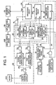
- Fig. 1 shows a block diagram of a system of the electronic clinical thermometer 100.
- a standard oscillator 1 applies a standard signal ⁇ o to a control signal generating circuit 2.
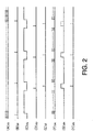
- the control signal generating circuit 2 generates a reset signal ⁇ r, a sampling signal ⁇ s, a lead signal ⁇ p, and a latch signal ⁇ l which are shown by (B), (C), (D), (E) of Fig. 2, respectively.
- a thermo-sensing oscillator 3 has a thermo-sensing element and generates a thermo-sensing signal ⁇ t the oscillating frequency of which changes in accordance with the change of temperature.
- the system has a present maximum temperature data holding device 20 for holding a present maximum value of the measured temperature in a period from the beginning of measurement.
- the holding device 20 comprises a temperature measuring circuit 6, a data storage circuit 7, and a comparing circuit 8.
- the system further has a measured temperature rise detecting device 21 comprising a temperature rise determining circuit 10, a stability detecting circuit 11, and a temperature data change determining circuit 12.
- An AND gate 4 for sampling the thermo-sensing signal ⁇ t is applied with the sampling signal ⁇ s from the control signal generating circuit 2 to one of input terminals, and applied with the thermo-sensing signal ⁇ t from the thermo-sensing oscillator circuit 3 at the other input terminal, thereby to generate a count signal ⁇ c as shown by waveforms (C), (A), (F) of Fig. 2.
- the count signal ⁇ c is applied to the temperature measuring circuit 6 of the present maximum temperature data holding device 20.
- the temperature measuring circuit 6 is initialized by the reset signal ⁇ r from the control signal generating circuit 2.
- the temperature measuring circuit 6 counts the number of count signals ⁇ c applied from the AND gate 4 during one sampling signal ⁇ s and generates a counted data which is applied to the data storage circuit 7 and the comparing circuit 8 as a temperature data signal Dt.
- the data storage circuit 7 stores a present maximum value Dm of the temperature data signal Dt.
- the comparing circuit 8 compares the present maximum value Dm of the temperature data signal which has last been stored in the data storage circuit 7 with a new temperature data signal Dt as a newly measured data of the temperature measuring circuit 6.
- the temperature data signal Dt is data of four digits.
- the temperature rise determining circuit 10 is applied with first and second coincidence signals S3 and S4 from the comparing circuit 8.
- a temperature rising signal ⁇ n is generated as shown by (G) of Fig. 2 so that an AND gate 9 is opened.
- the latch signal ⁇ l from the control signal generating circuit 2 passes through the AND gate 9, and is applied to the data storage circuit 7 as an updating signal ⁇ k shown by (H) of Fig. 2.
- the new temperature data signal Dt from the temperature measuring circuit 6 is written in the data storage circuit 7 as the present maximum value Dm.
- the temperature data change determining circuit 12 is applied with the first coincidence signal S3 from the comparing circuit 8. When the temperature data change determining circuit 12 determines that the temperature rises predetermined degrees (for example, 0.1°C), a temperature data change determining signal ⁇ m is generated.
- the present maximum value Dm of the temperature data signal from the data storage circuit 7 is applied to a decoder circuit 25 to be decoded to a pattern.
- the decoder circuit 25 applies an output signal to a display driving circuit 26 so that the digital display device 102 is driven.
- An AND gate 14 for detecting the stable state passes the latch signal ⁇ l when the stability detecting signal ⁇ e is applied thereto, and applies a stability trigger signal ⁇ e1 to a second sound signal forming circuit 15.
- the sound signal forming circuit 15 generates a stability informing sound signal ⁇ b2.
- An AND gate 16 for detecting the temperature data changing state passes the latch signal ⁇ l when the temperature data change determining signal ⁇ m is applied thereto, and applies a temperature data change trigger signal ⁇ m1 to a first sound signal forming circuit 17.
- the sound signal forming circuit 17 generates a temperature data change informing sound signal ⁇ b1.
- the sound signal forming circuits 15 and 17 are operated by the latch signal ⁇ 1 passed through the respective AND gates 14 and 16, the latch signal is also served as a synchronizing signal.
- An OR gate 18 is applied with the temperature data change informing sound signal ⁇ b1 and the stability informing sound signal ⁇ b2, and generates an informing signal ⁇ b.
- a buzzer driving circuit 19 is applied with the informing signal ⁇ b for driving the buzzer 103 so that an informing sound is generated.
- AND gates 14, 16, sound signal forming circuits 15, 17, OR gate 18, buzzer drivihg circuit 19 compose a buzzer driving device 30.
- Fig. 3 shows a block diagram of the maximum temperature data holding device 20 and the temperature data change determining circuit 12.
- the temperature measuring circuit 6 comprises four 1/10 frequency dividers 6a, 6b, 6c and 6d which are connected in series. Each of the frequency dividers has a counter.
- the frequency divider 6a is operated to count a unit of 10 degrees
- the frequency divider 6b counts a unit of 1 degrees
- the frequency divider 6c counts a unit of 0.1 degrees
- the frequency divider 6d counts a unit of 0.01 degrees.
- the data storage circuit 7 comprises four latch circuits 7a, 7b, 7c and 7d corresponding to the temperature measuring circuit 6.
- the comparing circuit 8 comprises four comparators 8a, 8b, 8c and 8d.
- the comparing circuit 8 generates the first coincidence signal S3 by three comparators 8a, 8b, 8c and the second coincidence signal S4 by the comparator 8d.
- the temperature measuring circuit 6 counts the count signal ⁇ c which is applied to the comparator 8d and transferred to the frequency dividers 6c, 6b and 6a in order, so that the temperature data signal Dt is produced. If the frequency divider 6a counts “3”, frequency divider 6b counts “7", frequency divider 6c counts "0”, and frequency divider 6d counts "0", the temperature information of 37.00°C is informed.
- the data storage circuit 7 stores the temperature information transmitted from the temperature measuring circuit 6 with a method, which will be described hereinafter.
- the latch circuits 7a to 7d of the data storage circuit 7 are formed such that the data of the frequency divider 6a is stored in the latch circuit 7a, the data of the frequency divider 6b is stored in the latch circuit 7b, the data of the frequency divider 6c is stored in the latch circuit 7c, and the data of the frequency divider 6d is stored in the latch circuit 7d.
- the comparing circuit 8 comprises a first comparing section having three comparators 8a to 8c in which the data of frequency dividers 6a to 6c of the temperature measuring circuit 6 representing higher three digits (lower precision) are compared with the data of the latch circuits 7a to 7c of the data storage circuit 7 for generating the first coincidence signal S3, and a second comparing section having the comparator 8d in which the data of frequency divider 6d of the temperature measuring circuit 6 representing the lower digit (higher precision) is compared with the data of the latch circuit 7d of the data storage circuit 7 representing the lower digit for generating the second coincidence signal S4.
- the temperature data change determining device 12 comprises a data type flip-flop 40 (hereinafter abbreviated to D-FF) applied with the sampling signal ⁇ s as a data signal, the first coincidence signal S3 as a clock signal, and the reset signal ⁇ r as a reset signal, an AND gate 41, and an R-S flip-flop 42 (hereinafter abbreviated to RS-FF).
- D-FF data type flip-flop 40
- RS-FF R-S flip-flop
- the temperature measuring circuit 6 counts the count signal ⁇ c applied to the frequency divider 6d and performs the carry to the frequency dividers 6c, 6b, 6a in order for producing the temperature data.
- the comparator 8d since the content of the frequency divider 6d is equal to the content of the latch circuit 7d at every output of the frequency divider 6d of 0.01 degree, the comparator 8d generates the second coincidence signal S4 of the lower digit at every output of the frequency divider 6d.
- the temperature measuring circuit 6 continues the counting operation, and then the content of the frequency divider 6a becomes equal to the content of the latch circuit 7a. Thereafter, the temperature data at the frequency divider 6b becomes equal to the content of the latch circuit 7b. Finally, the temperature data at the frequency divider 6c becomes equal to the content of the latch circuit 7c. Then, the first comparing section having three comparators 8a, 8b, 8c generates the first coincidence signal S3 of the higher digits which is applied to a terminal C of the D-FF 40 of the temperature data change determining circuit 12.
- the coincidence signal S3b is kept at the high level. At the next reset signal ⁇ r, the coincidence signal becomes the low level.
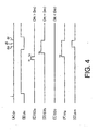
- the coincidence signal S3a shown by (C) of Fig. 4 means the fact that there is a coincidence in the comparator 8c for the unit digit of 0.1 degree, and the coincidence breaks thereafter.
- Dt-Dm>0.1 which continues after the signal. It means that the temperature rises 0.1°C or more.
- the coincidence signal S3a when the coincidence signal S3a is applied to the terminal C of the D-FF 40, the output signal ⁇ g of "H" level is generated from the output terminal Q of the D-FF 40 at the timing t2 of the negative-going.
- the coincidence signal S3b is applied to the terminal C, since the waveform is not negative-going, the output signal ⁇ g is not generated.
- the D-FF 40 generates the output signal ⁇ g to open the AND gate 41, so that the lead signal ⁇ p passed through the AND gate 41 is applied to the RS-FF 42 to set it.
- a temperature data change determining signal ⁇ m shown by (G) of Fig. 4 is generated from an output terminal Q.
- the temperature data change determining circuit 12 generates the temperature data change determining signal ⁇ m when the condition becomes Dt-Dm ⁇ 0.1 in the maximum temperature data holding device 20, namely only when the temperature rises 0.1°C.
- the maximum temperature data holding device 20 measures the temperature data signal Dt and updates the maximum value Dm at every sampling signal ⁇ s shown by (A) of Fig. 5, and produces the first and second coincidence signals S3 and S4 in accordance with respective conditions.
- the temperature on the display largely rises.
- the first coincidence signal S3 is generated at every sampling signal, and the temperature data change determining signal ⁇ m is generated every time from the temperature data change determining circuit 12.
- the AND gate 16 is opened by the temperature data change determining signal ⁇ m and the temperature data change trigger signal ⁇ m1 based on the latch signal ⁇ l passed through the AND gate 16 is applied to the first sound signal forming circuit 17.
- the output of the OR gate 18 is applied to the buzzer 103 through the buzzer driving circuit 19 for producing temperature change informing sound every time.
- the temperature rise determining circuit 10 generates the temperature rise signal ⁇ n since the condition of Dt>Dm exists every time, so that the maximum value Dm is updated every time.
- the stability detecting circuit 11 does not generate the stability detecting signal ⁇ e.
- the first coincidence signal S3 is not generated every time from the maximum temperature data holding device 20.
- the temperature data change informing signal ⁇ b1 generates every two sampling signals.
- the coincidence signal is generated every three time. As the time passes, a generating period of the coincidence signal is elongated.
- the temperature data change trigger signal ⁇ m1 and the temperature data change informing signal ⁇ b1 which synchronize with the temperature data change determining signal ⁇ m are changed to be generated every time in the interval Tl, every two times in the interval T2, and every three times in the interval T3 as shown by (C), (D) of Fig. 5.
- the generating period of the temperature change informing sound from the buzzer 103 becomes long.
- the temperature rise inclination reduces.
- the stability detecting circuit 11 generates the stability detecting signal ⁇ e.
- the AND gate 14 is opened by the stability detecting signal ⁇ e, and the stability trigger signal ⁇ e1 based on the latch signal ⁇ l passing through the AND gate 14 is applied to the second sound signal forming circuit 15.
- the output signal ⁇ b2 of the sound signal forming circuit 15 is applied to the buzzer driving circuit 19 passing through the OR gate 18.
- the buzzer 103 is operated by the output signal of the buzzer driving circuit 19 for producing a stability informing sound which is different from the temperature change informing sound. Thus, the end of the measuring operation is informed.
- the informing sound generating operation in the sequential operation of the temperature measurement as the informing signal ⁇ b shown by (G) of Fig. 5, in the interval T1 from the start of the measurement, the temperature change informing sound is generated by the temperature change informing signal ⁇ b1 every sampling signal ⁇ s which determines the measuring period.
- the generating period of the temperature change informing sound becomes small at a period of integer time as much as the period of the sampling signal ⁇ s.
- the stability informing sound is generated by the stability signal ⁇ b2 so that the end of the temperature measurement is informed.
- Fig. 6 shows characteristics of a temperature rising curve and an informing sound generating state corresponding to the temperature rise.
- the abscissa designates the sampling period ⁇ t and the ordinate designates the temperature rising value ⁇ T measured at every sampling period ⁇ t.
- a constant temperature rising value ⁇ T is 0.1°C as aforementioned.
- the temperature data change determining signal ⁇ m is generated from the temperature data change determining circuit 12.
- the temperature rises the value ⁇ T or more at every sampling as shown by a value ⁇ T1.
- the informing signal ⁇ b the temperature data change informing signal ⁇ b1 is generated at every sampling.
- the temperature does not rise the value ⁇ T at one sampling as shown by a value ⁇ T2.
- the temperature rises in excess of the value ⁇ T in the two periods of sampling.
- the temperature data change informing signal ⁇ b1 is generated every two times of sampling.
- the temperature data change informing signal ⁇ b1 is generated every three times of sampling as shown by a value ⁇ T3.
- the temperature data change informing signal ⁇ b1 is generated every five times of sampling as shown by a value ⁇ T4.
- the temperature data change informing signal ⁇ b1 is generated every seven times of sampling as shown by a value ⁇ T5.
- the stability detecting circuit 11 detects that the first and second coincidence signals S3 and S4 are in a coincident state at the same time and the coincident state continues for five times.
- the detecting signal ⁇ b2 is generated at the timing t6 in which a stability detecting signal ⁇ e is generated.
- the informing period of the buzzer is short so that the sound is produced at every measuring period, and that as the time passes, the informing period of the buzzer is gradually elongated. It is possible for the user to recognize the temperature measuring process and the end of the measurement by the buzzer information.
- An optional temperature rising value can be determined by selecting one of the comparators 8a to 8c which generate the first coincidence signal S3. If the sensing head of the electronic clinical thermometer is deviated from the measuring place, the buzzer is not driven. Thus, the fact that the buzzer does not emit sound informs the user that the deflection of the sensing head is deviated from the measuring place.
- an electronic clinical thermometer which informs not only the end of the measurement, but also the process of the measurement by the informing sound.
- the electronic clinical thermometer is extremely easy for the user to use, and may exactly measure the temperature. Furthermore, the temperature rising value is set by using the higher digit coincidence signal in the comparator, whereby the structure is simplified without increasing the manufacturing cost.
Landscapes
- Physics & Mathematics (AREA)
- General Physics & Mathematics (AREA)
- Measuring Temperature Or Quantity Of Heat (AREA)
- Measuring And Recording Apparatus For Diagnosis (AREA)
Claims (10)
- Elektronisches Medizinalthermometer, enthaltend einen Temperatursensorteil (3), und eine Informationseinrichtung (103) zum Informieren über den Temperaturanstieg während der Temperaturmessung durch einen Informationsschall auf der Grundlage eines Ausgangssignals ( t) des Temperaturerfassungsteils, dadurch gekennzeichnet, daß das elektronische Medizinalthermometer weiterhin enthält:wobeieine Wandlerschaltung (4) zum Umwandeln des Ausgangssignals ( t) des Temperaturerfassungsteils in digitale Signale ( c),einen Temperaturmeßteil (6) zum Messen einer Temperatur auf der Grundlage des digitalen Signals ( c) und zum Erzeugen eines Temperaturdatensignals (Dt),Speicherschaltungen (7) zum Speichern und Aktualisieren eines Maximalwerts des Temperaturdatensignals von dem Temperaturmeßteil,einen Datenvergleichsschaltung (8) zum Vergleichen des augenblicklichen Maximalwerts (Dm), der in den Speicherschaltungen gespeichert ist, mit dem Temperaturdatensignal (Dt), das von dem Temperaturmeßteil zugeführt wird,eine Temperaturanstiegserfassungsschaltung (21) zum Erfassen eines Anstiegsumfangs der Temperatur auf der Grundlage eines Vergleichsergebnisses der Datenvergleichsschaltungen,eine Summertreibervorrichtung (30), die auf der Grundlage von Signalen von der Temperaturanstiegserfassungsschaltung (21) betrieben wird,eine Informationseinrichtung (103), die von der Summertreibervorrichtung betrieben wird, um über den Anstieg der Temperatur durch Erzeugen eines Informationsschalls zu informieren,die Datenvergleichsschaltung dazu eingerichtet ist, ein erstes Übereinstimmungssignal (S3) durch Vergleichen des augenblicklichen Maximalwerts (Dm), der in den Speicherschaltungen gespeichert ist, mit dem Temperaturdatensignal (Dt) einer niedrigeren Genauigkeit zu erzeugen, und weiter dazu eingerichtet ist, ein zweites Übereinstimmungssignal (S4) durch Vergleichen des augenblicklichen Maximalwerts (Dm), der in den Speicherschaltungen gespeichert ist, mit dem Temperaturdatensignal einer höherer Genauigkeit, die genauer als die genannte niedrigere Genauigkeit ist, zu erzeugen,die Temperaturanstiegserfassungsschaltung eine Temperaturänderungsbestimmungsschaltung (12) enthält zum Erzeugen eines Temperaturänderungsbestimmungssignals ( m) d u rch Bestimmen des Anstiegs der Temperatur auf der Grundlage des ersten Übereinstimmungssignals (S3), und eine Stabilitätserfassungsschaltung (11) zum Erzeugen eines Stabilitätserfassungssignals ( e) durch Bestimmen der Stabilität der Temperatur auf der Grundlage sowohl des ersten Übereinstimmungssignals (S3) als auch des zweiten Übereinstimmungssignals (S4),die Summertreibervorrichtung (30) die Informationseinrichtung betreibt, um einen Informationsschall erster Art auf der Grundlage des Temperaturänderungsbestimmungssignals ( m) z u erzeugen und einen Informationsschall zweiter Art auf der Grundlage des Stabilitätserfassungssignals ( e) zu erzeugen.
- Elektronisches Medizinalthermometer nach Anspruch 1, bei dem die Temperaturänderungsbestimmungsschaltung das Bestimmungssignal erzeugt, wenn ein vorbestimmter konstanter Temperaturanstieg erfaßt wird.
- Elektronisches Medizinalthermometer nach Anspruch 1, weiterhin enthaltend eine Steuersignalgeneratorschaltung zum Erzeugen eines Abtastsignals zum Einstellen einer Betriebsperiode eines jeden Bauelements.
- Elektronisches Medizinalthermometer nach Anspruch 1, bei dem der Temperaturmeßteil Zählschaltungen zum Messen der Temperatur durch Zählen des digitalen Signals aufweist.
- Elektronisches Medizinalthermometer nach Anspruch 4, bei dem die Zählschaltungen das Temperaturdatensignal in der vorbestimmten Betriebsperiode erzeugen, die durch das Abtastsignal vorgegeben ist.
- Elektronisches Medizinalthermometer nach Anspruch 5, bei dem die Zählschaltungen weiterhin vierstellige, in Serie geschaltete Frequenzteiler enthalten.
- Elektronisches Medizinalthermometer nach Anspruch 6, bei dem die vierstelligen Frequenzteiler eine Einheit von 10°, eine Einheit von 1°, eine Einheit von 0,10° und eine Einheit von 0,01° von einer höheren zu einer niedrigeren Stelle aufweisen.
- Elektronisches Medizinalthermometer nach Anspruch 7, bei dem die obere Stelle drei Stellen von 10°, 1° und 0,1° und die untere Stelle eine Stelle von 0,01° umfaßt.
- Elektronisches Medizinalthermometer nach Anspruch 3, bei dem die Temperaturänderungsbestimmungsschaltung das Temperaturänderungsbestimmungssignal erzeugt, wenn ein erhöhtes erstes Übereinstimmungssignal während des Meßvorgangs abnimmt.
- Elektronisches Medizinalthermometer nach Anspruch 9, bei dem die Temperaturänderungsbestimmungsschaltung eine Zustandsbestimmungsschaltung (40) enthält, die die Abnahme des ersten Übereinstimmungssignals während des Abtastsignals ermittelt.
Applications Claiming Priority (1)
| Application Number | Priority Date | Filing Date | Title |
|---|---|---|---|
| PCT/JP1995/002228 WO1997016710A1 (en) | 1995-10-31 | 1995-10-31 | Electronic clinical thermometer |
Publications (3)
| Publication Number | Publication Date |
|---|---|
| EP0806641A1 EP0806641A1 (de) | 1997-11-12 |
| EP0806641A4 EP0806641A4 (de) | 1998-12-23 |
| EP0806641B1 true EP0806641B1 (de) | 2003-03-05 |
Family
ID=14126423
Family Applications (1)
| Application Number | Title | Priority Date | Filing Date |
|---|---|---|---|
| EP95935594A Expired - Lifetime EP0806641B1 (de) | 1995-10-31 | 1995-10-31 | Elektronisches medizinalthermometer |
Country Status (4)
| Country | Link |
|---|---|
| US (1) | US5892448A (de) |
| EP (1) | EP0806641B1 (de) |
| DE (1) | DE69529848T2 (de) |
| WO (1) | WO1997016710A1 (de) |
Families Citing this family (13)
| Publication number | Priority date | Publication date | Assignee | Title |
|---|---|---|---|---|
| US6412398B1 (en) | 2000-03-08 | 2002-07-02 | Trucook, Llc | Temperature sensing utensil with detachable head |
| US6591739B2 (en) | 2000-03-08 | 2003-07-15 | Trucook Llc | Temperature sensing utensil with detachable heads |
| US6864802B2 (en) | 2000-09-01 | 2005-03-08 | Ut-Battelle, Llc | Wireless spread-spectrum telesensor chip with synchronous digital architecture |
| US6774653B2 (en) * | 2001-08-22 | 2004-08-10 | Sun Microsystems, Inc. | Two-pin thermal sensor calibration interface |
| USD479807S1 (en) | 2001-12-17 | 2003-09-23 | Trucook Llc | Temperature sensing utensil |
| US20030158683A1 (en) * | 2002-02-19 | 2003-08-21 | Claude Gauthier | Temperature calibration using on-chip electrical fuses |
| US6937958B2 (en) | 2002-02-19 | 2005-08-30 | Sun Microsystems, Inc. | Controller for monitoring temperature |
| US6806698B2 (en) * | 2002-02-19 | 2004-10-19 | Sun Microsystems, Inc. | Quantifying a difference between nodal voltages |
| US6996491B2 (en) * | 2002-02-19 | 2006-02-07 | Sun Microsystems, Inc. | Method and system for monitoring and profiling an integrated circuit die temperature |
| US6893154B2 (en) * | 2002-02-19 | 2005-05-17 | Sun Microsystems, Inc. | Integrated temperature sensor |
| US6809557B2 (en) * | 2002-02-19 | 2004-10-26 | Sun Microsystems, Inc. | Increasing power supply noise rejection using linear voltage regulators in an on-chip temperature sensor |
| US6874933B1 (en) * | 2002-10-15 | 2005-04-05 | National Semiconductor Corporation | Apparatus for digital temperature measurement in an integrated circuit |
| JP4627261B2 (ja) * | 2003-09-30 | 2011-02-09 | シチズンホールディングス株式会社 | 電子体温計 |
Family Cites Families (14)
| Publication number | Priority date | Publication date | Assignee | Title |
|---|---|---|---|---|
| JPS58211610A (ja) * | 1982-06-02 | 1983-12-09 | Seiko Instr & Electronics Ltd | 体温計 |
| US4541734A (en) * | 1982-06-24 | 1985-09-17 | Terumo Kabushiki Kaisha | Electronic clinical thermometer, and method of measuring body temperature |
| US4592000A (en) * | 1982-06-24 | 1986-05-27 | Terumo Corporation | Electronic clinical thermometer, and method of measuring body temperature |
| DE3346285A1 (de) * | 1982-12-21 | 1984-10-11 | Terumo K.K., Tokio/Tokyo | Elektronisches klinisches thermometer und verfahren zur koerpertemperaturmessung |
| US4574359A (en) * | 1982-12-21 | 1986-03-04 | Terumo Kabushiki Kaisha | Electronic clinical thermometer, and method of measuring body temperature |
| JPS59128536A (ja) * | 1983-01-14 | 1984-07-24 | Nippon Shokubai Kagaku Kogyo Co Ltd | 紫外線硬化用組成物 |
| JPS59128536U (ja) * | 1983-02-18 | 1984-08-29 | オムロン株式会社 | 体温計 |
| JPS59135441U (ja) * | 1983-02-28 | 1984-09-10 | オムロン株式会社 | 電子体温計 |
| JPS59135441A (ja) * | 1983-12-14 | 1984-08-03 | Hitachi Ltd | 光導波路スイツチ |
| JPS60220832A (ja) * | 1984-04-18 | 1985-11-05 | Sharp Corp | 電子式体温計 |
| DE3420074A1 (de) * | 1984-05-29 | 1985-12-05 | Karl-Nikolaus 8871 Winterbach Oberschmid | Koerpertemperatur-messsonde speziell fuer die landwirtschaftliche tierhaltung |
| JPS61102836A (ja) * | 1984-10-24 | 1986-05-21 | Toshiba Corp | メツセ−ジ通信方式 |
| JPS61102836U (de) * | 1984-12-10 | 1986-06-30 | ||
| US5626425A (en) * | 1995-02-06 | 1997-05-06 | Becton Dickinson And Company | Electronic thermometer with audible temperature rise indicator |
-
1995
- 1995-10-31 DE DE69529848T patent/DE69529848T2/de not_active Expired - Fee Related
- 1995-10-31 US US08/722,223 patent/US5892448A/en not_active Expired - Fee Related
- 1995-10-31 EP EP95935594A patent/EP0806641B1/de not_active Expired - Lifetime
- 1995-10-31 WO PCT/JP1995/002228 patent/WO1997016710A1/ja not_active Ceased
Also Published As
| Publication number | Publication date |
|---|---|
| EP0806641A1 (de) | 1997-11-12 |
| DE69529848T2 (de) | 2003-09-04 |
| WO1997016710A1 (en) | 1997-05-09 |
| US5892448A (en) | 1999-04-06 |
| DE69529848D1 (de) | 2003-04-10 |
| EP0806641A4 (de) | 1998-12-23 |
Similar Documents
| Publication | Publication Date | Title |
|---|---|---|
| US5892448A (en) | Electronic clinical thermometer | |
| US4551031A (en) | Electronic clinical thermometer | |
| US4461584A (en) | Electronic clinical thermometer | |
| US4762429A (en) | Electronic clinical thermometer with a battery life warning display | |
| US4201087A (en) | Apparatus for measuring temperature | |
| EP0726451B1 (de) | Elektronisches Thermometer mit hörbarem Temperaturanstieg | |
| KR930013677A (ko) | 변위 측정장치 | |
| US6788044B2 (en) | Frequency change measuring device | |
| US6369563B1 (en) | Method for high resolution measurement of a position | |
| US4725150A (en) | Digital thermometer with varying resolution | |
| EP0168640A2 (de) | Elektronisches Thermometer zum Ermitteln und zur Anzeige von steigenden, fallenden und stabilen Temperaturen | |
| JP3160137B2 (ja) | 電波修正時計 | |
| US20030193843A1 (en) | Method for high resolution measurement of a position | |
| CA1130485A (en) | Measurement indicating apparatus and method | |
| US5874949A (en) | Horizontal synchronizing signal frequency measuring instrument for multi-synchronism type display unit | |
| EP0885373B1 (de) | Verfahren zur hochauflösenden messung einer zeitspanne | |
| JPH0511455Y2 (de) | ||
| JP2998314B2 (ja) | アブソリュートスケール装置 | |
| JPWO1997016710A1 (ja) | 電子体温計 | |
| JP2858345B2 (ja) | 電子式水深計 | |
| US4879908A (en) | Suction air measuring device | |
| EP0537144B1 (de) | Methode und Vorrichtung zum Kodieren und Lesen von Daten | |
| JP2532371B2 (ja) | 変位量測定回路 | |
| JPH0124600Y2 (de) | ||
| JPH0313709Y2 (de) |
Legal Events
| Date | Code | Title | Description |
|---|---|---|---|
| PUAI | Public reference made under article 153(3) epc to a published international application that has entered the european phase |
Free format text: ORIGINAL CODE: 0009012 |
|
| AK | Designated contracting states |
Kind code of ref document: A1 Designated state(s): DE FR GB IT |
|
| 17P | Request for examination filed |
Effective date: 19961016 |
|
| A4 | Supplementary search report drawn up and despatched |
Effective date: 19981109 |
|
| AK | Designated contracting states |
Kind code of ref document: A4 Designated state(s): DE FR GB IT |
|
| 17Q | First examination report despatched |
Effective date: 20001019 |
|
| RAP1 | Party data changed (applicant data changed or rights of an application transferred) |
Owner name: CITIZEN WATCH CO. LTD. |
|
| GRAG | Despatch of communication of intention to grant |
Free format text: ORIGINAL CODE: EPIDOS AGRA |
|
| GRAG | Despatch of communication of intention to grant |
Free format text: ORIGINAL CODE: EPIDOS AGRA |
|
| GRAH | Despatch of communication of intention to grant a patent |
Free format text: ORIGINAL CODE: EPIDOS IGRA |
|
| GRAH | Despatch of communication of intention to grant a patent |
Free format text: ORIGINAL CODE: EPIDOS IGRA |
|
| GRAA | (expected) grant |
Free format text: ORIGINAL CODE: 0009210 |
|
| AK | Designated contracting states |
Designated state(s): DE FR GB IT |
|
| REG | Reference to a national code |
Ref country code: GB Ref legal event code: FG4D |
|
| REF | Corresponds to: |
Ref document number: 69529848 Country of ref document: DE Date of ref document: 20030410 Kind code of ref document: P |
|
| ET | Fr: translation filed | ||
| PLBE | No opposition filed within time limit |
Free format text: ORIGINAL CODE: 0009261 |
|
| STAA | Information on the status of an ep patent application or granted ep patent |
Free format text: STATUS: NO OPPOSITION FILED WITHIN TIME LIMIT |
|
| 26N | No opposition filed |
Effective date: 20031208 |
|
| PGFP | Annual fee paid to national office [announced via postgrant information from national office to epo] |
Ref country code: FR Payment date: 20041008 Year of fee payment: 10 |
|
| REG | Reference to a national code |
Ref country code: GB Ref legal event code: 746 Effective date: 20040921 |
|
| PGFP | Annual fee paid to national office [announced via postgrant information from national office to epo] |
Ref country code: GB Payment date: 20041027 Year of fee payment: 10 |
|
| PGFP | Annual fee paid to national office [announced via postgrant information from national office to epo] |
Ref country code: DE Payment date: 20041028 Year of fee payment: 10 |
|
| REG | Reference to a national code |
Ref country code: FR Ref legal event code: D6 |
|
| PG25 | Lapsed in a contracting state [announced via postgrant information from national office to epo] |
Ref country code: IT Free format text: LAPSE BECAUSE OF NON-PAYMENT OF DUE FEES;WARNING: LAPSES OF ITALIAN PATENTS WITH EFFECTIVE DATE BEFORE 2007 MAY HAVE OCCURRED AT ANY TIME BEFORE 2007. THE CORRECT EFFECTIVE DATE MAY BE DIFFERENT FROM THE ONE RECORDED. Effective date: 20051031 Ref country code: GB Free format text: LAPSE BECAUSE OF NON-PAYMENT OF DUE FEES Effective date: 20051031 |
|
| PG25 | Lapsed in a contracting state [announced via postgrant information from national office to epo] |
Ref country code: DE Free format text: LAPSE BECAUSE OF NON-PAYMENT OF DUE FEES Effective date: 20060503 |
|
| GBPC | Gb: european patent ceased through non-payment of renewal fee |
Effective date: 20051031 |
|
| PG25 | Lapsed in a contracting state [announced via postgrant information from national office to epo] |
Ref country code: FR Free format text: LAPSE BECAUSE OF NON-PAYMENT OF DUE FEES Effective date: 20060630 |
|
| REG | Reference to a national code |
Ref country code: FR Ref legal event code: ST Effective date: 20060630 |