EP0807313B1 - Disjoncteur de protection de ligne - Google Patents
Disjoncteur de protection de ligne Download PDFInfo
- Publication number
- EP0807313B1 EP0807313B1 EP96901231A EP96901231A EP0807313B1 EP 0807313 B1 EP0807313 B1 EP 0807313B1 EP 96901231 A EP96901231 A EP 96901231A EP 96901231 A EP96901231 A EP 96901231A EP 0807313 B1 EP0807313 B1 EP 0807313B1
- Authority
- EP
- European Patent Office
- Prior art keywords
- contact
- lever
- neutral conductor
- circuit breaker
- conductor terminal
- Prior art date
- Legal status (The legal status is an assumption and is not a legal conclusion. Google has not performed a legal analysis and makes no representation as to the accuracy of the status listed.)
- Expired - Lifetime
Links
- 239000004020 conductor Substances 0.000 claims abstract description 85
- 230000007935 neutral effect Effects 0.000 claims abstract description 42
- 230000007246 mechanism Effects 0.000 claims abstract description 11
- 238000000034 method Methods 0.000 claims description 6
- 230000008569 process Effects 0.000 claims description 6
- 230000006870 function Effects 0.000 claims description 4
- 230000009471 action Effects 0.000 claims description 2
- 238000006073 displacement reaction Methods 0.000 claims description 2
- 238000013459 approach Methods 0.000 claims 1
- 230000000694 effects Effects 0.000 description 3
- 210000000629 knee joint Anatomy 0.000 description 3
- 238000004804 winding Methods 0.000 description 3
- 230000008901 benefit Effects 0.000 description 2
- 230000003628 erosive effect Effects 0.000 description 2
- 238000010791 quenching Methods 0.000 description 2
- 230000000171 quenching effect Effects 0.000 description 2
- 238000003466 welding Methods 0.000 description 2
- 230000002411 adverse Effects 0.000 description 1
- 230000000712 assembly Effects 0.000 description 1
- 238000000429 assembly Methods 0.000 description 1
- 230000008859 change Effects 0.000 description 1
- 230000006835 compression Effects 0.000 description 1
- 238000007906 compression Methods 0.000 description 1
- 238000010276 construction Methods 0.000 description 1
- 230000003111 delayed effect Effects 0.000 description 1
- 238000011161 development Methods 0.000 description 1
- 230000018109 developmental process Effects 0.000 description 1
- 230000001771 impaired effect Effects 0.000 description 1
- 210000003127 knee Anatomy 0.000 description 1
- 210000000056 organ Anatomy 0.000 description 1
- 230000009993 protective function Effects 0.000 description 1
- 230000002829 reductive effect Effects 0.000 description 1
- 230000000284 resting effect Effects 0.000 description 1
- 230000000717 retained effect Effects 0.000 description 1
- 239000000725 suspension Substances 0.000 description 1
Images
Classifications
-
- H—ELECTRICITY
- H01—ELECTRIC ELEMENTS
- H01H—ELECTRIC SWITCHES; RELAYS; SELECTORS; EMERGENCY PROTECTIVE DEVICES
- H01H71/00—Details of the protective switches or relays covered by groups H01H73/00 - H01H83/00
- H01H71/002—Details of the protective switches or relays covered by groups H01H73/00 - H01H83/00 with provision for switching the neutral conductor
Definitions
- the invention relates to a circuit breaker with a thermal and magnetically protected outer conductor pole and an unprotected neutral conductor pole according to the preamble of claim 1.
- Such a circuit breaker is known from EP 0 599 800 A1.
- a contact device of the outer conductor pole and the Neutral conductor pole within a common housing with the usual pole width arranged side by side in parallel planes.
- Both contact devices are by an angled one arranged in the arc quenching chamber of the outer conductor pole Inner shell separated from each other. Therefore, the room is in front of the Arc quenching device significantly restricted at least on one side.
- Both contact devices are coupled via one in the inner shell guided slide, which in turn on coaxially arranged bearing axes associated jumpers.
- the two switching bridges each supported by a compression spring in the same Direction of rotation swiveled.
- Switch bridges that are directly coupled are particularly affected the switching operations each other considerably. so that the protective function of the Overall conductor pole is adversely affected overall.
- the invention has for its object a circuit breaker at the beginning mentioned type so that the switching function and operation of the Outer conductor pole unchanged compared to a normal circuit breaker the spatial arrangement of the switching mechanism is retained. Release organs and arcing chamber area are only insignificantly impaired, and in particular welding both the outer conductor and the Neutral conductor contact is reliably prevented.
- the invention has the advantage that the protected outer conductor pole as a normal Miniature circuit breaker works and mainly from unchanged parts of one such switch is formed. With the same housing size is also in this Construction of the unprotected neutral conductor pole integrated in a space-saving and functional manner. In addition, it is ensured that only the Neutral conductor contact closes automatically by its own contact spring and only then the outer conductor contact. In the closed position of the neutral conductor contact the frictional connection to the contact device of the outer conductor pole is also complete canceled. Its contact lever can ultimately be free as with a single one Swing the circuit breaker into the closed position.
- phase conductor contact only opens.
- the contact lever itself initially moved in the direction of the magnet system Switch-off phase the degree of freedom between the outer conductor contact and Neutral conductor contact still enlarged and the contact lever of the outer conductor pole can open completely unaffected by the neutral pole. Only after putting one back predetermined contact opening distance, a slide provides the frictional connection Contact lever of the neutral conductor pole and opens this after the foundedleiterpol.
- the contact spring reduces the moving Neutral conductor contact very quickly their counterforce to the contact spring of the External conductor contact, which is hardly delayed.
- the main advantage of the arrangement according to the invention results in the Opening process in the event of a short circuit. After unlatching the Switch lock the blow of the magnetic core for accelerated opening of the External conductor contact directly on the arranged in the same direction Transfer slider, so that this time shifted just as suddenly on the Neutral conductor contact acts in the opening direction. The welding of the The neutral conductor contact is therefore similar to the outer conductor contact the impact of the magnetic trigger is reliably prevented.
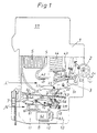
- the circuit breaker shown only partially open has only one with its outer contours indicated switch housing 1, which consists of two half-shells is composed in a known manner and approximately in the drawing level Is 18 mm thick, that is, has a common pole width as a pitch. That with its outer contours the relevant standard dimensions for miniature circuit breakers corresponding switch housing takes one inside Switch mechanism 2, a contact device 3 for the protected Outer conductor pole "L”, a magnetic release 4, a switching and arcing chamber 5 and a thermal trigger 6.
- the aforementioned assemblies 2 to 6 exist largely from existing components of a normal single-pole circuit breaker and are both in their arrangement as well practically unchanged in their function compared to such a switch.
- connection terminals Only in the housing base 1.1 are in the conventional area Connection terminals require significant changes to the inner housing contours, on the one hand, enough space for twice the number of terminals to receive (one input and one output terminal each for the outer conductor pole and the neutral conductor pole) and additionally in the input terminal area 1.2 Arrangement of a contact device 7 for the neutral conductor pole "N" in addition to that to enable necessary mechanical and electrical components.
- this is the core of the Contact device 7 relating to the invention for the neutral conductor pole "N" laterally below the thermal release 6 in the housing base 1.1 in immediate Neighboring the associated input terminal 8 arranged.
- the works Contact device 7 in the same, but slightly height-offset movement plane (corresponds to the drawing level). like the contact device 3 for the outer conductor pole "L".
- the contact device 7 consists essentially of a double-armed contact lever 7.1, which is about a housing-fixed axis 7.2 is pivotable, and at its the actual contact point 7.3 opposite free lever end 7.11 with a to be described in more detail Slider 9 cooperates.
- the contact lever 7.1 works under the effect its contact spring 7.4 on a fixed contact piece 8.1, which as angled extension is connected directly to the input terminal 8, which in turn by means of a terminal box 8.2 and a terminal screw 8.3 the connection of a neutral conductor, not shown.
- contact lever 7.1 leads, on the other hand, a merely indicated, sufficiently insulated electrical Connection 7.6 across the switch housing to the opposite of the Input terminal 8 arranged on the top, not shown Output terminal of the neutral conductor pole.
- the same size Input terminal is arranged for the outer conductor pole and from the latter by means of an insert 1.3 (indicated by dash-dot lines) in the Sectioned base.
- An electrical connection leads from this terminal directly to the foot point 6.1 of the thermal release 6 (indicated schematically by means of a short piece of flexible conductor 6.2) which is sufficiently insulated from the contact device 7 is arranged.
- the triggering of the switching mechanism 2 causes overcurrent, a flexible Line 6.4 to the pivotable contact lever 3.1 as part of the contact device 3 of the protected outer conductor pole.
- the contact lever 3.1 of the outer conductor pole is with its slot on one Axis 3.2 fixed to the housing is pivotally mounted and at the same time by a small amount Value can be moved laterally, for example in addition to the build-up of the contact pressure Compensate for changes due to erosion at the contact end 3.3 can. So that the contact lever works on a fixed contact piece 4.1, which About a so-called contact horn 4.2 in a yoke 4.3 of the Magnetic trigger 4 is included. which in turn has a winding 4.4 frame-like encloses.
- the current path of the outer conductor pole leads directly from the winding an output terminal, not shown, on the top of the switch housing.
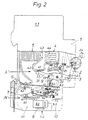
- the winding 4.4 surrounds a magnetic core 4.5, at least in the event of a short circuit a trigger lever 2.1 shown only partially around a housing-fixed axis 2.2 pivoted counterclockwise and the in a known manner Switch mechanism 2 triggers on his knee joint lever 2.3, so that the Contact lever 3.1 from the closed position shown in Figure 2 to the open position can pivot according to Figure 1.
- the contact spring 3.4 of the outer conductor pole which is considerably stronger than the contact spring 7.4 of the neutral conductor pole.
- Latter is also designed as a tension spring and with its longer, slightly angled hook-shaped eyelet in an eye 7.5 of the contact lever approximately in the middle between the axis 7.2 and the contact point 7.3 hooked in, while their shorter Eyelet grips over a fixed bolt 1.5.
- the location of this pin 1.5 is there spatially assigned to the contact lever 7.1 such that the contact spring 7.4 in the Switch-on position (Fig. 2) on an already effective relatively short lever arm pulls while in the off position (Fig. 1) the lever arm almost the value "zero" reached.
- the circuit breaker is manually operated on the manual control unit 2.4 and the knee joint lever 2.3 located in the over-dead center position in the 2, the contact lever 3.1 pivots about its Axis 3.2 and takes the slider 9 clockwise with the pin 9.1.
- the lever end resting on the push surface 9.2 moves in the same direction 7.11 under the action of the contact spring 7.4, the pivoting moment on the Contact lever 7.1 becomes increasingly larger due to the displacement of the eye 7.5.
- the contact point 7.3 has the fixed contact piece 8.1 reached, it arrives there, the contact spring 7.4 now being the largest Unleashes power and alone applies the contact pressure. Only then does the Contact lever 3.1 with its contact-side end 3.3, the fixed contact piece 4.1 and closes the outer conductor pole.
Landscapes
- Breakers (AREA)
- Treatments For Attaching Organic Compounds To Fibrous Goods (AREA)
- Maintenance And Management Of Digital Transmission (AREA)
- Details Of Aerials (AREA)
- Switch Cases, Indication, And Locking (AREA)
- Emergency Protection Circuit Devices (AREA)
- Recrystallisation Techniques (AREA)
- Ignition Installations For Internal Combustion Engines (AREA)
Claims (11)
- Disjoncteur de protection de ligne comportant un pôle de conducteur de phase (L) protégé thermiquement et magnétiquement et un pôle de conducteur neutre (N) non protégé, à chacun desquels est associé un système de contacts (7) formé d'un contact fixe (8.1) et d'un levier de contact (7.1) pivotant, les deux systèmes de contacts étant disposés conjointement dans un boítier de disjoncteur (1) avec seulement une largeur de pôle normale, étant couplés mécaniquement l'un à l'autre et étant commandés par un mécanisme de commutation (2) actionnable manuellement, caractérisé en ce queles deux systèmes de contacts (3, 7), rapporté au plan fonctionnel du mécanisme de commutation (2), sont disposés l'un au-dessus de l'autre dans ledit plan, avec des points d'articulation (3.2 et 7.2) séparés dans l'espace pour leur levier de contact (3.1, 7.1) ;lors du processus de fermeture et de coupure, les leviers de contact (3.1, 7.1) qui sont couplés à l'aide d'une tige coulissante (9), en partie par obstacle, en partie par adhérence, et sont sollicités par un ressort, pivotent chacun dans des sens opposés autour de leur point d'articulation (3.2 et 7.2) ;la tige coulissante (9) est disposée pratiquement sur le prolongement de l'axe du déclencheur magnétique (4) comportant une armature (4.5) ;la direction d'actionnement de la tige coulissante (9) se confond avec la direction de travail de l'armature (4.5), de telle sorte qu'en cas de court-circuit, le levier de contact (7.1) du pôle de conducteur neutre (N) est lui aussi sollicité directement dans la direction d'ouverture par l'armature (4.5), qui agit brusquement sur le levier de contact (3.1) du pôle de conducteur de phase (L).
- Disjoncteur de protection de ligne selon la revendication 1, caractérisé en ce que la tige coulissante (9), d'un côté est montée mobile sur le levier de contact (3.1) du pôle de conducteur de phase (L), entre le point d'articulation (3.2) de celui-ci et le point de contact (3.3) du conducteur de phase et, de l'autre côté, agit par une surface de poussée (9.2) sur le levier de contact (7.1) à deux bras du pôle de conducteur neutre (N), à l'extrémité (7.11) libre du levier éloignée du point de contact (7.3) de conducteur neutre.
- Disjoncteur de protection de ligne selon les revendications 1 et 2, caractérisé en ce que les deux leviers de contact (3.1, 7.1), par des ressorts de contact (3.4, 7.4) qui agissent sur eux dans le même sens de rotation, lors de l'opération de fermeture ou de coupure, sont au moins temporairement en prise mutuelle par adhérence par l'intermédiaire de la tige coulissante (9).
- Disjoncteur de protection de ligne selon une des revendications 1 à 3, caractérisé en ce que le levier de contact (7.1) du pôle de conducteur neutre (N) est sollicité uniquement dans la direction de fermeture du contact par le ressort de traction (7.4), qui agit sur ledit levier entre son point d'articulation (7.2) et son point de contact (7.3).
- Disjoncteur de protection de ligne selon les revendications 1 à 4, caractérisé en ce que le ressort de traction (ressort de contact 7.4) qui agit sur le levier de contact (7.1) du pôle de conducteur neutre (N) est suspendu entre ses deux points de fixation (7.5, 1.5) de telle sorte que, lorsque le levier de contact (7.1) de conducteur neutre s'ouvre, la direction de sa force pivote presque jusqu'à son point d'articulation (7.2) et passe rapidement dans une position de quasi point mort, de sorte que le moment du ressort de traction (7.4) agissant sur le levier de contact (7.1) ouvert, dans la direction de fermeture de celui-ci, tend vers la valeur « zéro »
- Disjoncteur de protection de ligne selon une des revendications 1 à 4, caractérisé en ce que le levier de contact (3.1) de conducteur de phase lors d'une opération de coupure, pendant la première phase d'ouverture du contact n'est retenu par aucune force antagoniste du levier de contact (7.1) de conducteur neutre et travaille comme un disjoncteur de protection de ligne unipolaire courant.
- Disjoncteur de protection de ligne selon une des revendications 1 à 6, caractérisé en ce que les deux leviers de contact (3.1, 7.1) sont disposés en regard l'un de l'autre, entre les contacts fixes (4.1 et 8.1) et, au niveau de leurs extrémités côté contact (3.3, 7.3) respectives sont déplacés dans la même direction, mais dans des sens de rotation opposés, lors de la commutation.
- Disjoncteur de protection de ligne selon une des revendications 1 à 7, caractérisé en ce que les usures des contacts au niveau des systèmes de contacts (3.7) du pôle de conducteur de phase (L) et du pôle de conducteur neutre (N) se compensent mutuellement.
- Disjoncteur de protection de ligne selon une des revendications 1 à 8, caractérisé en ce que le système de contacts (7) pour le pôle de conducteur neutre (N) est disposé dans le socle (1.1) du boítier dans le voisinage immédiat de bornes d'entrée (8).
- Disjoncteur de protection de ligne selon une des revendications 1 à 9, caractérisé en ce que la tige coulissante (9) liée à un tourillon (9.1) du levier de contact (3.1) du pôle de conducteur de phase (L), à son extrémité libre (surface de poussée 9.2) agissant sur le levier de contact (7.1) du pôle de conducteur neutre (N) est seulement guidée latéralement dans le socle de boítier (1.1).
- Disjoncteur de protection de ligne selon une des revendications 1 à 10, caractérisé en ce que le conducteur de phase (L) protégé, avec ses éléments essentiels (2, 3, 4, 5, 6) est construit principalement à partir d'éléments fonctionnels de même type que ceux d'un disjoncteur de protection de ligne normal existant, sans pôle de conducteur neutre (N).
Applications Claiming Priority (3)
| Application Number | Priority Date | Filing Date | Title |
|---|---|---|---|
| DE19503530A DE19503530B4 (de) | 1995-02-03 | 1995-02-03 | Leitungsschutzschalter |
| DE19503530 | 1995-02-03 | ||
| PCT/DE1996/000166 WO1996024150A1 (fr) | 1995-02-03 | 1996-02-02 | Disjoncteur de protection de ligne |
Publications (2)
| Publication Number | Publication Date |
|---|---|
| EP0807313A1 EP0807313A1 (fr) | 1997-11-19 |
| EP0807313B1 true EP0807313B1 (fr) | 2002-05-15 |
Family
ID=7753099
Family Applications (1)
| Application Number | Title | Priority Date | Filing Date |
|---|---|---|---|
| EP96901231A Expired - Lifetime EP0807313B1 (fr) | 1995-02-03 | 1996-02-02 | Disjoncteur de protection de ligne |
Country Status (8)
| Country | Link |
|---|---|
| EP (1) | EP0807313B1 (fr) |
| AT (1) | ATE217731T1 (fr) |
| CZ (1) | CZ286737B6 (fr) |
| DE (2) | DE19503530B4 (fr) |
| HU (1) | HU221487B (fr) |
| PL (1) | PL180036B1 (fr) |
| SI (1) | SI9620029A (fr) |
| WO (1) | WO1996024150A1 (fr) |
Cited By (1)
| Publication number | Priority date | Publication date | Assignee | Title |
|---|---|---|---|---|
| CN102332370A (zh) * | 2011-09-06 | 2012-01-25 | 浙江加西亚电子电器有限公司 | 一种小型漏电断路器 |
Families Citing this family (6)
| Publication number | Priority date | Publication date | Assignee | Title |
|---|---|---|---|---|
| DE19725000A1 (de) * | 1997-06-13 | 1998-12-17 | Abb Patent Gmbh | Installationsschaltgerät |
| DE10102708B4 (de) * | 2001-01-22 | 2004-08-26 | Aeg Niederspannungstechnik Gmbh & Co Kg | Leitungsschutzschalter |
| AT504033B1 (de) * | 2003-07-17 | 2012-03-15 | Moeller Gebaeudeautomation Kg | Schutzschalter |
| DE102006036194B4 (de) * | 2006-08-01 | 2019-09-26 | Siemens Aktiengesellschaft | Schaltvorrichtung mit Schaltstellenpaar |
| DE102006036191A1 (de) * | 2006-08-01 | 2008-02-07 | Siemens Ag | Schaltvorrichtung |
| CN107146745B (zh) * | 2016-03-01 | 2020-02-18 | 浙江正泰电器股份有限公司 | 电子式漏电断路器 |
Family Cites Families (7)
| Publication number | Priority date | Publication date | Assignee | Title |
|---|---|---|---|---|
| DE3038511A1 (de) * | 1980-10-11 | 1982-06-03 | Ellenberger & Poensgen Gmbh, 8503 Altdorf | Ueberstromschutzschalter |
| EP0054499B1 (fr) * | 1980-12-16 | 1984-06-13 | Legrand | Disjoncteur à sectionnement de neutre |
| DE3242062A1 (de) * | 1982-11-13 | 1984-05-17 | Brown, Boveri & Cie Ag, 6800 Mannheim | Elektrischer schalter |
| DE3410157A1 (de) * | 1984-03-20 | 1985-09-26 | Brown, Boveri & Cie Ag, 6800 Mannheim | Elektrischer schalter mit je einer schaltkontaktstelle fuer einen phasenleiter und fuer einen nulleiter |
| DE4329100A1 (de) * | 1992-10-08 | 1994-04-14 | Abb Patent Gmbh | Elektrischer Schalter |
| AT402583B (de) * | 1992-11-25 | 1997-06-25 | Felten & Guilleaume Ag Oester | Leitungsschutzschalter mit einem thermisch und magnetisch geschützten aussenleiterpol und einem ungeschützten nulleiterpol |
| EP0630035B1 (fr) * | 1993-06-15 | 1997-05-21 | Heinrich Kopp Ag | Interrupteur auxiliaire et de signalisation pour appareils interrupteurs de protection |
-
1995
- 1995-02-03 DE DE19503530A patent/DE19503530B4/de not_active Expired - Fee Related
-
1996
- 1996-02-02 DE DE59609216T patent/DE59609216D1/de not_active Expired - Fee Related
- 1996-02-02 SI SI9620029A patent/SI9620029A/sl not_active IP Right Cessation
- 1996-02-02 HU HU9800194A patent/HU221487B/hu not_active IP Right Cessation
- 1996-02-02 PL PL96321260A patent/PL180036B1/pl not_active IP Right Cessation
- 1996-02-02 CZ CZ19972418A patent/CZ286737B6/cs not_active IP Right Cessation
- 1996-02-02 WO PCT/DE1996/000166 patent/WO1996024150A1/fr not_active Ceased
- 1996-02-02 AT AT96901231T patent/ATE217731T1/de not_active IP Right Cessation
- 1996-02-02 EP EP96901231A patent/EP0807313B1/fr not_active Expired - Lifetime
Cited By (1)
| Publication number | Priority date | Publication date | Assignee | Title |
|---|---|---|---|---|
| CN102332370A (zh) * | 2011-09-06 | 2012-01-25 | 浙江加西亚电子电器有限公司 | 一种小型漏电断路器 |
Also Published As
| Publication number | Publication date |
|---|---|
| ATE217731T1 (de) | 2002-06-15 |
| PL180036B1 (en) | 2000-12-29 |
| HUP9800194A3 (en) | 2000-03-28 |
| HUP9800194A2 (hu) | 1998-06-29 |
| EP0807313A1 (fr) | 1997-11-19 |
| HU221487B (en) | 2002-10-28 |
| DE19503530B4 (de) | 2006-07-06 |
| DE19503530A1 (de) | 1996-08-08 |
| CZ241897A3 (cs) | 1999-01-13 |
| DE59609216D1 (de) | 2002-06-20 |
| PL321260A1 (en) | 1997-11-24 |
| CZ286737B6 (en) | 2000-06-14 |
| SI9620029A (sl) | 1998-02-28 |
| WO1996024150A1 (fr) | 1996-08-08 |
Similar Documents
| Publication | Publication Date | Title |
|---|---|---|
| DE69312154T2 (de) | Mechanische Verriegelungsvorrichtung von zwei Schaltern mit Isolierstoff-Formgehäuse | |
| DE19602118C2 (de) | Elektrisches Schaltgerät | |
| DE3540055C2 (de) | Elektrisches Schaltgerät | |
| DE3119482C2 (de) | Stromkreisunterbrecher | |
| EP0272457B1 (fr) | Déclencheur magnétique pour un disjoncteur opérant sélectivement | |
| DE1933576C2 (de) | Strombegrenzungsschalter | |
| EP0807313B1 (fr) | Disjoncteur de protection de ligne | |
| DE3737539C2 (fr) | ||
| EP1760748A2 (fr) | Appareil de commutation électrique | |
| DE2616554C2 (de) | Elektrischer Installationsschalter, insbesondere Leitungsschutzschalter mit Fehlerstromschutzeinrichtung | |
| DE69014741T2 (de) | Betätigungsmechanismus für elektrischen Schalter. | |
| DE102005041232A1 (de) | Elektrisches Schaltgerät | |
| EP0091040B1 (fr) | Disjoncteur de protection à courant excessif | |
| DE2343908C2 (de) | Stromunterbrecher mit Überstrom- und Hilfs-Auslösung | |
| DE102004018275B4 (de) | Schaltgerät | |
| DE1286188B (de) | Installationsselbstschalter mit Hilfskontakt | |
| DE3725860A1 (de) | Mehrpoliger schaltungsunterbrecher | |
| DE10322654A1 (de) | Schaltgerät | |
| DE4339425B4 (de) | Schaltschloß für einen Fehlerstromschutzschalter | |
| EP0592007B1 (fr) | Dispositif de commutation | |
| DE3524813C2 (fr) | ||
| EP0310943B1 (fr) | Appareil de commutation électrique | |
| DE69833637T2 (de) | Selektiver Auslöser für Leistungsschalter | |
| DE9302253U1 (de) | Schaltvorrichtung für Leistungsschaltgeräte | |
| AT404647B (de) | Elektrischer schutzschalter |
Legal Events
| Date | Code | Title | Description |
|---|---|---|---|
| PUAI | Public reference made under article 153(3) epc to a published international application that has entered the european phase |
Free format text: ORIGINAL CODE: 0009012 |
|
| 17P | Request for examination filed |
Effective date: 19970801 |
|
| AK | Designated contracting states |
Kind code of ref document: A1 Designated state(s): AT BE CH DE DK ES FR GB GR IE IT LI LU MC NL PT SE |
|
| GRAG | Despatch of communication of intention to grant |
Free format text: ORIGINAL CODE: EPIDOS AGRA |
|
| 17Q | First examination report despatched |
Effective date: 19980216 |
|
| GRAG | Despatch of communication of intention to grant |
Free format text: ORIGINAL CODE: EPIDOS AGRA |
|
| GRAH | Despatch of communication of intention to grant a patent |
Free format text: ORIGINAL CODE: EPIDOS IGRA |
|
| GRAH | Despatch of communication of intention to grant a patent |
Free format text: ORIGINAL CODE: EPIDOS IGRA |
|
| GRAA | (expected) grant |
Free format text: ORIGINAL CODE: 0009210 |
|
| AK | Designated contracting states |
Kind code of ref document: B1 Designated state(s): AT BE CH DE DK ES FR GB GR IE IT LI LU MC NL PT SE |
|
| PG25 | Lapsed in a contracting state [announced via postgrant information from national office to epo] |
Ref country code: IE Free format text: LAPSE BECAUSE OF FAILURE TO SUBMIT A TRANSLATION OF THE DESCRIPTION OR TO PAY THE FEE WITHIN THE PRESCRIBED TIME-LIMIT Effective date: 20020515 Ref country code: GB Free format text: LAPSE BECAUSE OF FAILURE TO SUBMIT A TRANSLATION OF THE DESCRIPTION OR TO PAY THE FEE WITHIN THE PRESCRIBED TIME-LIMIT Effective date: 20020515 |
|
| REF | Corresponds to: |
Ref document number: 217731 Country of ref document: AT Date of ref document: 20020615 Kind code of ref document: T |
|
| REG | Reference to a national code |
Ref country code: GB Ref legal event code: FG4D Free format text: NOT ENGLISH Ref country code: CH Ref legal event code: EP |
|
| REG | Reference to a national code |
Ref country code: IE Ref legal event code: FG4D Free format text: GERMAN |
|
| REF | Corresponds to: |
Ref document number: 59609216 Country of ref document: DE Date of ref document: 20020620 |
|
| PG25 | Lapsed in a contracting state [announced via postgrant information from national office to epo] |
Ref country code: SE Free format text: LAPSE BECAUSE OF FAILURE TO SUBMIT A TRANSLATION OF THE DESCRIPTION OR TO PAY THE FEE WITHIN THE PRESCRIBED TIME-LIMIT Effective date: 20020815 Ref country code: DK Free format text: LAPSE BECAUSE OF FAILURE TO SUBMIT A TRANSLATION OF THE DESCRIPTION OR TO PAY THE FEE WITHIN THE PRESCRIBED TIME-LIMIT Effective date: 20020815 |
|
| PG25 | Lapsed in a contracting state [announced via postgrant information from national office to epo] |
Ref country code: PT Free format text: LAPSE BECAUSE OF FAILURE TO SUBMIT A TRANSLATION OF THE DESCRIPTION OR TO PAY THE FEE WITHIN THE PRESCRIBED TIME-LIMIT Effective date: 20020816 |
|
| ET | Fr: translation filed | ||
| GBV | Gb: ep patent (uk) treated as always having been void in accordance with gb section 77(7)/1977 [no translation filed] |
Effective date: 20020515 |
|
| PG25 | Lapsed in a contracting state [announced via postgrant information from national office to epo] |
Ref country code: ES Free format text: LAPSE BECAUSE OF FAILURE TO SUBMIT A TRANSLATION OF THE DESCRIPTION OR TO PAY THE FEE WITHIN THE PRESCRIBED TIME-LIMIT Effective date: 20021128 |
|
| REG | Reference to a national code |
Ref country code: IE Ref legal event code: FD4D Ref document number: 0807313E Country of ref document: IE |
|
| PGFP | Annual fee paid to national office [announced via postgrant information from national office to epo] |
Ref country code: MC Payment date: 20030206 Year of fee payment: 8 |
|
| PGFP | Annual fee paid to national office [announced via postgrant information from national office to epo] |
Ref country code: AT Payment date: 20030221 Year of fee payment: 8 |
|
| PGFP | Annual fee paid to national office [announced via postgrant information from national office to epo] |
Ref country code: LU Payment date: 20030227 Year of fee payment: 8 |
|
| PGFP | Annual fee paid to national office [announced via postgrant information from national office to epo] |
Ref country code: CH Payment date: 20030304 Year of fee payment: 8 |
|
| PLBE | No opposition filed within time limit |
Free format text: ORIGINAL CODE: 0009261 |
|
| STAA | Information on the status of an ep patent application or granted ep patent |
Free format text: STATUS: NO OPPOSITION FILED WITHIN TIME LIMIT |
|
| 26N | No opposition filed |
Effective date: 20030218 |
|
| PG25 | Lapsed in a contracting state [announced via postgrant information from national office to epo] |
Ref country code: LU Free format text: LAPSE BECAUSE OF NON-PAYMENT OF DUE FEES Effective date: 20040202 Ref country code: AT Free format text: LAPSE BECAUSE OF NON-PAYMENT OF DUE FEES Effective date: 20040202 |
|
| PG25 | Lapsed in a contracting state [announced via postgrant information from national office to epo] |
Ref country code: MC Free format text: LAPSE BECAUSE OF NON-PAYMENT OF DUE FEES Effective date: 20040228 |
|
| PG25 | Lapsed in a contracting state [announced via postgrant information from national office to epo] |
Ref country code: LI Free format text: LAPSE BECAUSE OF NON-PAYMENT OF DUE FEES Effective date: 20040229 Ref country code: CH Free format text: LAPSE BECAUSE OF NON-PAYMENT OF DUE FEES Effective date: 20040229 |
|
| REG | Reference to a national code |
Ref country code: CH Ref legal event code: PL |
|
| PGFP | Annual fee paid to national office [announced via postgrant information from national office to epo] |
Ref country code: DE Payment date: 20050330 Year of fee payment: 10 |
|
| PG25 | Lapsed in a contracting state [announced via postgrant information from national office to epo] |
Ref country code: DE Free format text: LAPSE BECAUSE OF NON-PAYMENT OF DUE FEES Effective date: 20060901 |
|
| PG25 | Lapsed in a contracting state [announced via postgrant information from national office to epo] |
Ref country code: GR Free format text: LAPSE BECAUSE OF NON-PAYMENT OF DUE FEES Effective date: 20020515 |
|
| PGFP | Annual fee paid to national office [announced via postgrant information from national office to epo] |
Ref country code: NL Payment date: 20090224 Year of fee payment: 14 |
|
| REG | Reference to a national code |
Ref country code: NL Ref legal event code: V1 Effective date: 20100901 |
|
| PG25 | Lapsed in a contracting state [announced via postgrant information from national office to epo] |
Ref country code: NL Free format text: LAPSE BECAUSE OF NON-PAYMENT OF DUE FEES Effective date: 20100901 |
|
| PGFP | Annual fee paid to national office [announced via postgrant information from national office to epo] |
Ref country code: IT Payment date: 20110225 Year of fee payment: 16 Ref country code: FR Payment date: 20110309 Year of fee payment: 16 |
|
| PGFP | Annual fee paid to national office [announced via postgrant information from national office to epo] |
Ref country code: BE Payment date: 20110224 Year of fee payment: 16 |
|
| BERE | Be: lapsed |
Owner name: *AEG NIEDERSPANNUNGSTECHNIK G.M.B.H. Effective date: 20120228 |
|
| REG | Reference to a national code |
Ref country code: FR Ref legal event code: ST Effective date: 20121031 |
|
| PG25 | Lapsed in a contracting state [announced via postgrant information from national office to epo] |
Ref country code: IT Free format text: LAPSE BECAUSE OF NON-PAYMENT OF DUE FEES Effective date: 20120202 |
|
| PG25 | Lapsed in a contracting state [announced via postgrant information from national office to epo] |
Ref country code: BE Free format text: LAPSE BECAUSE OF NON-PAYMENT OF DUE FEES Effective date: 20120228 |
|
| PG25 | Lapsed in a contracting state [announced via postgrant information from national office to epo] |
Ref country code: FR Free format text: LAPSE BECAUSE OF NON-PAYMENT OF DUE FEES Effective date: 20120229 |