EP0807452B1 - Träger für Apparaturen, der sich an der äusseren Fläche eines zylindrischen Behälters abstützen kann - Google Patents
Träger für Apparaturen, der sich an der äusseren Fläche eines zylindrischen Behälters abstützen kann Download PDFInfo
- Publication number
- EP0807452B1 EP0807452B1 EP19970401021 EP97401021A EP0807452B1 EP 0807452 B1 EP0807452 B1 EP 0807452B1 EP 19970401021 EP19970401021 EP 19970401021 EP 97401021 A EP97401021 A EP 97401021A EP 0807452 B1 EP0807452 B1 EP 0807452B1
- Authority
- EP
- European Patent Office
- Prior art keywords
- brackets
- support
- stirrups
- support according
- fastening belt
- Prior art date
- Legal status (The legal status is an assumption and is not a legal conclusion. Google has not performed a legal analysis and makes no representation as to the accuracy of the status listed.)
- Expired - Lifetime
Links
- 125000006850 spacer group Chemical group 0.000 claims description 16
- 239000007788 liquid Substances 0.000 claims description 6
- 229930195733 hydrocarbon Natural products 0.000 claims description 3
- 150000002430 hydrocarbons Chemical class 0.000 claims description 3
- 230000000284 resting effect Effects 0.000 claims description 2
- 238000009434 installation Methods 0.000 description 5
- 230000007797 corrosion Effects 0.000 description 3
- 238000005260 corrosion Methods 0.000 description 3
- 239000006260 foam Substances 0.000 description 3
- XEEYBQQBJWHFJM-UHFFFAOYSA-N Iron Chemical compound [Fe] XEEYBQQBJWHFJM-UHFFFAOYSA-N 0.000 description 2
- 239000003208 petroleum Substances 0.000 description 2
- 230000001681 protective effect Effects 0.000 description 2
- XLYOFNOQVPJJNP-UHFFFAOYSA-N water Substances O XLYOFNOQVPJJNP-UHFFFAOYSA-N 0.000 description 2
- 238000003466 welding Methods 0.000 description 2
- 239000003795 chemical substances by application Substances 0.000 description 1
- 238000002485 combustion reaction Methods 0.000 description 1
- 239000002826 coolant Substances 0.000 description 1
- 238000007872 degassing Methods 0.000 description 1
- 238000006073 displacement reaction Methods 0.000 description 1
- 230000002349 favourable effect Effects 0.000 description 1
- 238000005187 foaming Methods 0.000 description 1
- 230000008595 infiltration Effects 0.000 description 1
- 238000001764 infiltration Methods 0.000 description 1
- 235000000396 iron Nutrition 0.000 description 1
- 229910052742 iron Inorganic materials 0.000 description 1
- 238000012423 maintenance Methods 0.000 description 1
- 238000004519 manufacturing process Methods 0.000 description 1
- 239000000203 mixture Substances 0.000 description 1
- 230000005855 radiation Effects 0.000 description 1
- 239000007921 spray Substances 0.000 description 1
Images



Classifications
-
- A—HUMAN NECESSITIES
- A62—LIFE-SAVING; FIRE-FIGHTING
- A62C—FIRE-FIGHTING
- A62C3/00—Fire prevention, containment or extinguishing specially adapted for particular objects or places
- A62C3/06—Fire prevention, containment or extinguishing specially adapted for particular objects or places of highly inflammable material, e.g. light metals, petroleum products
Definitions
- the present invention relates to a support equipment intended to be mounted on a surface cylindrical. It allows in particular cold mounting, without welds, sprinkler rings for tanks containing flammable liquids, intended to spray water or foam to cool the walls of said tanks by fire and supporting bridges, electrical cables and piping.
- the invention finds its application in all factories where equipment must be supported by rigid walls cylindrical elements including petroleum refineries, production platforms for petroleum and flammable deposits.
- This device includes a fixing belt, designed to at least partially surround a tank of storage, at least one crown support fixed to said belt and extending radially outward.
- the fixing belt is in contact on one of its faces, over its entire length with the tank skirt creating a large area infiltration and water retention.
- This device can be installed without welding on the tank, so without draining and degassing the tank. However in in many cases, this installation mode is only provisional.
- the purpose of the present invention is to remedy these drawbacks. For this it offers a equipment support designed to be easily mounted on a rigid wall of a cylindrical element and creating zones to risk of corrosion as low as possible
- the support of the invention includes a plurality of consoles intended to support the equipment, one fastening belt provided with tensioning means, intended for be tightened to retain the brackets on the rigid wall of the cylindrical element characterized in that the brackets are independent of the fixing belt and in that it further includes spacers which in cooperation with the consoles are suitable for holding the seat belt fixing away from the rigid wall of the element cylindrical, over its entire length.
- the spacers are profiled elements in the form of U, comprising a base and two perpendicular branches, the faces of the ends of the branches resting on the rigid wall of the cylindrical element.
- the brackets are profiles with the same shape as the stirrups spacers extended perpendicular to their bases by equipment support arms.
- the support arms include at least two parts mechanically adjustable.
- the fastening belt has a flat face which rests on the bases of the spacers and brackets.
- the stirrups and consoles are provided on their bases with guides which limit their sliding relative to the seat belt fixation.
- the branches of spacers and brackets have lights for the passage of the fixing belt.
- the invention is also a tank notably of hydrocarbons equipped with support according to the invention, said support being intended for support a sprinkler ring fitted with projection of liquid, placed around the tank and supplied with pressurized liquid.
- the invention includes a support mounting device consisting of hooks which have a long straight part integral with a magnetic suction cup and a short part curved on the side opposite to said suction cup.
- the brackets 2 and the brackets 5, are arranged around the skirt 6 of the reservoir 1 and held in place by pressure against the skirt 6 under the action of the belt 3 which is tightened by means 4 of tension.
- Belt 3, the consoles 2 and the stirrups thus mounted, the belt 3 is moved away from the skirt 6 of the tank, which reduces the contact surface between the skirt 6 and the elements of the support. Areas where corrosion can occur develop are reduced.
- Belt 3 is made in several pieces easy to handle and set up.
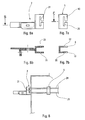
- a spacer 5 in the shape of a U comprising a base 8 and two branches 9 and 10 perpendicular to the base 8, of which the faces 11 and 12 of the ends are supported on the skirt 6 of the tank 1.
- the belt 3 carried out by means of a flat iron rests on the face 8 of the bracket 5 and on the base 14 of the console 2, to maintain these two parts pressed against the skirt 6 of the tank 1.
- the spacer 5 has a guide 19 and the console 2 a guide 18, which limit the sliding of the belt 3.
- the branches of U 9, 10 and 9bis and 10bis, respectively stirrups 5 and spacers consoles 2 have lights 20, 22 and 21 and 23.
- the belt 3 consists of round profile irons, which are arranged in upper and lower parts of the lights, as shown in the figure 8.
- Figures 9 and 10 illustrate the application particular from the inventor's support, to the support of a ring 30 for watering a tank 1 of products flammable.
- the crown 30 provided with microgenerators 31 of foam is fed by a mixture of water and agent foaming under pressure.
- the foam sprayed on the tank skirt constitutes a protective film for the skirt against the thermal radiation emitted by hydrocarbons in combustion around the tank. Thanks to the free space between the belt and the skirt the film can develop without break and play its role of protective screen.
- the crown consists of several sections to facilitate handling.
- the 17 brackets are welded to the crown 30 by the welds 32.
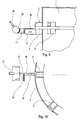
- the subject of the invention is therefore a device for mounting of the support illustrated in FIGS. 11 and 12, constituted by a hook 29 which has a part 27 long integral with a magnetic suction cup 26 and a part 28 short curved on the side opposite to the suction cup 26.
- the belt 3 is put in place, tightened by action on the tensioning means 4.
- the hooks 29 are then withdrawn.
- Another advantage of the invention is the possibility to weld the consoles 2 on the cylindrical surface for a final assembly and to remove the belt 3 and the stirrups 5 of spacing, these elements being reusable on a other installation.
Landscapes
- Chemical & Material Sciences (AREA)
- Engineering & Computer Science (AREA)
- Chemical Kinetics & Catalysis (AREA)
- General Chemical & Material Sciences (AREA)
- Oil, Petroleum & Natural Gas (AREA)
- Health & Medical Sciences (AREA)
- Public Health (AREA)
- Business, Economics & Management (AREA)
- Emergency Management (AREA)
- Details Or Accessories Of Spraying Plant Or Apparatus (AREA)
- Clamps And Clips (AREA)
- Filling Or Discharging Of Gas Storage Vessels (AREA)
Claims (9)
- Träger für eine Vorrichtung, der zur Anbringung auf einer starren Wandung (6) eines zylindrischen Elements (1) vorgesehen ist und eine Vielzahl von Tragstützen (2) aufweist, die zum Abstützen der Vorrichtung bestimmt sind, sowie eine Umfassung (3) zur Befestigung, welche mit Spanneinrichtungen (4) versehen und zum Festklemmen bestimmt ist, um die Tragstützen (2) auf der starren Wandung (6) des zylindrischen Elements zu halten, dadurch gekennzeichnet, dass die Tragstützen (2) von der Umfassung (3) zur Befestigung unabhängig sind, und dass er außerdem Abstandsbügel (5) aufweist, die im Zusammenwirken mit den Tragstützen (2) zum Halten der Umfassung (3) zur Befestigung im Abstand von der starren Wandung (6) des zylindrischen Elements (1) über die ganze Länge ausgebildet sind.
- Träger nach Anspruch 1, dadurch gekennzeichnet, dass die Abstandsbügel (5) Elemente mit U-Profil sind, welche eine Basis (8) und zwei senkrechte Schenkel (9 und 10) aufweisen, wobei sich die Flächen (11 und 12) der Enden der Schenkel (9 und 10) auf der starren Wandung (6) des zylindrischen Elements (1) abstützen.
- Träger nach Anspruch 1 oder 2, dadurch gekennzeichnet, dass die Tragstützen (2) Profilteile mit gleicher Form wie die Abstandsbügel (5) sind, welche senkrecht zu ihrer Basis (14) durch Stützarme (13) zum Abstützen der Vorrichtung verlängert sind.
- Träger nach Anspruch 3, dadurch gekennzeichnet, dass die Stützarme (13) mindestens zwei Teile umfassen, die einstellbar mechanisch verbunden sind.
- Träger nach Anspruch 3 oder 4, dadurch gekennzeichnet, dass die Umfassung (3) zur Befestigung eine ebene Fläche aufweist, die sich auf den Basisteilen (8 und 14) der Abstandsbügel (5) und der Tragstützen (2) abstützt.
- Träger nach Anspruch 5, dadurch gekennzeichnet, dass die Bügel (5) und die Tragstützen (2) an ihrer jeweiligen Basis (8 und 14) mit Führungen (18 und 19) versehen sind, welche deren Gleitbewegung bezüglich der Umfassung (3) zur Befestigung begrenzen.
- Träger nach Anspruch 3 oder 4, dadurch gekennzeichnet, dass die Schenkel (9 und 10) der Abstandsbügel (5) und der Tragstützen (2) Langlöcher (20, 21, 22 und 23) für den Durchtritt der Umfassung (3) zur Befestigung aufweisen.
- Mit einem Träger nach einem der Ansprüche 1 bis 7 ausgerüsteter Behälter, insbesondere für Kohlenwasserstoffe, dadurch gekennzeichnet, dass der Träger zum Abstützen eines Berieselungskranzes (30) bestimmt ist, welcher eine Einrichtung (31) zum Verspritzen von Flüssigkeit aufweist, die um den Behälter (1) angeordnet ist und der eine unter Druck stehende Flüssigkeit zugeführt wird.
- Vorrichtung zum Anbringen des Trägers nach einem der Ansprüche 1 bis 8, dadurch gekennzeichnet, dass er aus Haken (29) besteht, welche einen geradlinigen langgestreckten Abschnitt (27), der fest mit einem Magnetventil (26) verbunden ist, und einen kurzen umgebogenen Abschnitt (28) aufweisen, der sich auf der dem Ventil (26) gegenüber liegenden Seite befindet.
Applications Claiming Priority (2)
| Application Number | Priority Date | Filing Date | Title |
|---|---|---|---|
| FR9605988 | 1996-05-14 | ||
| FR9605988A FR2748786B1 (fr) | 1996-05-14 | 1996-05-14 | Support d'un equipement destine a etre monte sur une paroi d'un element cylindrique |
Publications (2)
| Publication Number | Publication Date |
|---|---|
| EP0807452A1 EP0807452A1 (de) | 1997-11-19 |
| EP0807452B1 true EP0807452B1 (de) | 2001-04-04 |
Family
ID=9492116
Family Applications (1)
| Application Number | Title | Priority Date | Filing Date |
|---|---|---|---|
| EP19970401021 Expired - Lifetime EP0807452B1 (de) | 1996-05-14 | 1997-05-06 | Träger für Apparaturen, der sich an der äusseren Fläche eines zylindrischen Behälters abstützen kann |
Country Status (3)
| Country | Link |
|---|---|
| EP (1) | EP0807452B1 (de) |
| DE (1) | DE69704447D1 (de) |
| FR (1) | FR2748786B1 (de) |
Family Cites Families (3)
| Publication number | Priority date | Publication date | Assignee | Title |
|---|---|---|---|---|
| BR6101373U (pt) * | 1981-10-01 | 1981-12-22 | Ucerpo S A Ideias Pesquisas E | Gola-calha aplicada na borda superior externa dos tanques de combustivel para seu resfriamento |
| FR2638143A1 (en) * | 1988-10-21 | 1990-04-27 | Iglesias Angel | Device for fixing particularly crown rings, for example spraying rings, on tanks containing inflammable products |
| FR2725629A1 (fr) * | 1994-10-12 | 1996-04-19 | Total Raffinage Distribution | Structure de pulverisation d'un liquide, apte a equiper une enceinte de stockage d'un produit combustible, et enceinte equipee de cette structure |
-
1996
- 1996-05-14 FR FR9605988A patent/FR2748786B1/fr not_active Expired - Fee Related
-
1997
- 1997-05-06 DE DE69704447T patent/DE69704447D1/de not_active Expired - Lifetime
- 1997-05-06 EP EP19970401021 patent/EP0807452B1/de not_active Expired - Lifetime
Also Published As
| Publication number | Publication date |
|---|---|
| DE69704447D1 (de) | 2001-05-10 |
| FR2748786B1 (fr) | 1998-07-10 |
| FR2748786A1 (fr) | 1997-11-21 |
| EP0807452A1 (de) | 1997-11-19 |
Similar Documents
| Publication | Publication Date | Title |
|---|---|---|
| WO2013093262A1 (fr) | Cuve etanche et isolante munie d'un dispositif de retenue | |
| EP3495037A1 (de) | System zur verteilung einer flüssigen und/oder gasförmigen phase in einer reaktionskammer | |
| EP0807452B1 (de) | Träger für Apparaturen, der sich an der äusseren Fläche eines zylindrischen Behälters abstützen kann | |
| EP0237770A1 (de) | Aufblasbare Dichtung, bei der die Anpressung durch Druckentlastung erfolgt | |
| FR2600396A1 (fr) | Ensemble de rupture et procede de liberation de pression | |
| FR2564409A1 (fr) | Vehicule d'intervention | |
| EP0428433A1 (de) | Vorrichtung zum Fixieren der Steuerstabsführungsplatte im Kernreaktordruckgefäss | |
| FR2629146A1 (fr) | Dispositif de jonction par " clipsage " de deux panneaux ou profiles | |
| BE1009992A4 (fr) | Structure de pulverisation d'un liquide, apte a equiper une enceinte de stockage d'un produit combustible, et enceinte equipee de cette structure | |
| FR2638143A1 (en) | Device for fixing particularly crown rings, for example spraying rings, on tanks containing inflammable products | |
| FR2739169A1 (fr) | Collier de prise en charge pour le branchement d'un abonne sur une canalisation d'alimentation en eau et procede de percement de la canalisation | |
| EP0604339A1 (de) | Zusammenfügendes Verkeilelement | |
| EP0090097B1 (de) | Feuerfeste Auskleidung für Schmelzofen | |
| FR3027258A1 (fr) | Systeme de protection d'un bouchon d'un reservoir a carburant | |
| EP0578596A1 (de) | Ofen, insbesondere elektrische Ofen für die Behandlung von geschmolzen Metallen | |
| FR3150497A1 (fr) | Dispositif de guidage pour tour de chargement et/ou de déchargement de fluide cryogénique | |
| FR2906006A1 (fr) | Collier de serrage d'un element tubulaire muni d'un sabot d'absorption des vibrations en matiere plastique | |
| FR2695952A1 (fr) | Ancrage notamment pour tuyaux en béton. | |
| FR2659880A1 (fr) | Dispositif de liaison entre un recipient metallurgique contenant un metal liquide et une lingotiere. | |
| FR2864906A1 (fr) | Ensemble et dispositif de protection d'une tete d'aspersion pour la lutte contre l'incendie | |
| FR2615928A1 (fr) | Procede et installation destines a la mise en place d'une cuve de stockage de gaz sous pression, ainsi que la cuve adaptee | |
| FR2707886A1 (fr) | Dispositif pour l'évacuation d'un fluide à l'intérieur d'un conteneur ainsi qu'un tel conteneur. | |
| FR3123106A1 (fr) | Procédé de fermeture d’une membrane d’étanchéité pour cuve étanche et thermiquement isolante | |
| FR2893961A1 (fr) | Abri a troncons mobiles. | |
| FR3165300A1 (fr) | Dispositif de stockage pour un gaz sous pression |
Legal Events
| Date | Code | Title | Description |
|---|---|---|---|
| PUAI | Public reference made under article 153(3) epc to a published international application that has entered the european phase |
Free format text: ORIGINAL CODE: 0009012 |
|
| 17P | Request for examination filed |
Effective date: 19970509 |
|
| AK | Designated contracting states |
Kind code of ref document: A1 Designated state(s): BE DE DK ES FR GB GR IE IT LU NL PT |
|
| GRAG | Despatch of communication of intention to grant |
Free format text: ORIGINAL CODE: EPIDOS AGRA |
|
| GRAG | Despatch of communication of intention to grant |
Free format text: ORIGINAL CODE: EPIDOS AGRA |
|
| GRAH | Despatch of communication of intention to grant a patent |
Free format text: ORIGINAL CODE: EPIDOS IGRA |
|
| 17Q | First examination report despatched |
Effective date: 20000831 |
|
| GRAH | Despatch of communication of intention to grant a patent |
Free format text: ORIGINAL CODE: EPIDOS IGRA |
|
| GRAA | (expected) grant |
Free format text: ORIGINAL CODE: 0009210 |
|
| AK | Designated contracting states |
Kind code of ref document: B1 Designated state(s): BE DE DK ES FR GB GR IE IT LU NL PT |
|
| PG25 | Lapsed in a contracting state [announced via postgrant information from national office to epo] |
Ref country code: NL Free format text: LAPSE BECAUSE OF FAILURE TO SUBMIT A TRANSLATION OF THE DESCRIPTION OR TO PAY THE FEE WITHIN THE PRESCRIBED TIME-LIMIT Effective date: 20010404 Ref country code: IT Free format text: LAPSE BECAUSE OF FAILURE TO SUBMIT A TRANSLATION OF THE DESCRIPTION OR TO PAY THE FEE WITHIN THE PRE;WARNING: LAPSES OF ITALIAN PATENTS WITH EFFECTIVE DATE BEFORE 2007 MAY HAVE OCCURRED AT ANY TIME BEFORE 2007. THE CORRECT EFFECTIVE DATE MAY BE DIFFERENT FROM THE ONE RECORDED.SCRIBED TIME-LIMIT Effective date: 20010404 Ref country code: IE Free format text: LAPSE BECAUSE OF FAILURE TO SUBMIT A TRANSLATION OF THE DESCRIPTION OR TO PAY THE FEE WITHIN THE PRESCRIBED TIME-LIMIT Effective date: 20010404 Ref country code: GB Free format text: LAPSE BECAUSE OF FAILURE TO SUBMIT A TRANSLATION OF THE DESCRIPTION OR TO PAY THE FEE WITHIN THE PRESCRIBED TIME-LIMIT Effective date: 20010404 |
|
| REG | Reference to a national code |
Ref country code: IE Ref legal event code: FG4D Free format text: FRENCH |
|
| PG25 | Lapsed in a contracting state [announced via postgrant information from national office to epo] |
Ref country code: LU Free format text: LAPSE BECAUSE OF NON-PAYMENT OF DUE FEES Effective date: 20010506 |
|
| REF | Corresponds to: |
Ref document number: 69704447 Country of ref document: DE Date of ref document: 20010510 |
|
| PG25 | Lapsed in a contracting state [announced via postgrant information from national office to epo] |
Ref country code: BE Free format text: LAPSE BECAUSE OF NON-PAYMENT OF DUE FEES Effective date: 20010531 |
|
| PG25 | Lapsed in a contracting state [announced via postgrant information from national office to epo] |
Ref country code: PT Free format text: LAPSE BECAUSE OF FAILURE TO SUBMIT A TRANSLATION OF THE DESCRIPTION OR TO PAY THE FEE WITHIN THE PRESCRIBED TIME-LIMIT Effective date: 20010704 |
|
| PG25 | Lapsed in a contracting state [announced via postgrant information from national office to epo] |
Ref country code: DE Free format text: LAPSE BECAUSE OF FAILURE TO SUBMIT A TRANSLATION OF THE DESCRIPTION OR TO PAY THE FEE WITHIN THE PRESCRIBED TIME-LIMIT Effective date: 20010705 |
|
| PG25 | Lapsed in a contracting state [announced via postgrant information from national office to epo] |
Ref country code: GR Free format text: LAPSE BECAUSE OF FAILURE TO SUBMIT A TRANSLATION OF THE DESCRIPTION OR TO PAY THE FEE WITHIN THE PRESCRIBED TIME-LIMIT Effective date: 20010706 |
|
| NLV1 | Nl: lapsed or annulled due to failure to fulfill the requirements of art. 29p and 29m of the patents act | ||
| GBV | Gb: ep patent (uk) treated as always having been void in accordance with gb section 77(7)/1977 [no translation filed] |
Effective date: 20010404 |
|
| PG25 | Lapsed in a contracting state [announced via postgrant information from national office to epo] |
Ref country code: DK Free format text: LAPSE BECAUSE OF FAILURE TO SUBMIT A TRANSLATION OF THE DESCRIPTION OR TO PAY THE FEE WITHIN THE PRESCRIBED TIME-LIMIT Effective date: 20011012 |
|
| PG25 | Lapsed in a contracting state [announced via postgrant information from national office to epo] |
Ref country code: ES Free format text: LAPSE BECAUSE OF FAILURE TO SUBMIT A TRANSLATION OF THE DESCRIPTION OR TO PAY THE FEE WITHIN THE PRESCRIBED TIME-LIMIT Effective date: 20011030 |
|
| BERE | Be: lapsed |
Owner name: ELF ANTAR FRANCE Effective date: 20010531 |
|
| PLBE | No opposition filed within time limit |
Free format text: ORIGINAL CODE: 0009261 |
|
| STAA | Information on the status of an ep patent application or granted ep patent |
Free format text: STATUS: NO OPPOSITION FILED WITHIN TIME LIMIT |
|
| REG | Reference to a national code |
Ref country code: IE Ref legal event code: FD4D |
|
| 26N | No opposition filed | ||
| PG25 | Lapsed in a contracting state [announced via postgrant information from national office to epo] |
Ref country code: FR Free format text: LAPSE BECAUSE OF NON-PAYMENT OF DUE FEES Effective date: 20020329 |
|
| REG | Reference to a national code |
Ref country code: FR Ref legal event code: ST |
|
| PG25 | Lapsed in a contracting state [announced via postgrant information from national office to epo] |
Ref country code: FR Free format text: LAPSE BECAUSE OF NON-PAYMENT OF DUE FEES Effective date: 20010531 |