EP0807497B1 - Méthode de fonctionnement pour un espace de travail comprenant un robot asservi à une presse à cintrer pour traiter des tôles métalliques - Google Patents
Méthode de fonctionnement pour un espace de travail comprenant un robot asservi à une presse à cintrer pour traiter des tôles métalliques Download PDFInfo
- Publication number
- EP0807497B1 EP0807497B1 EP97201416A EP97201416A EP0807497B1 EP 0807497 B1 EP0807497 B1 EP 0807497B1 EP 97201416 A EP97201416 A EP 97201416A EP 97201416 A EP97201416 A EP 97201416A EP 0807497 B1 EP0807497 B1 EP 0807497B1
- Authority
- EP
- European Patent Office
- Prior art keywords
- robot
- press
- metal sheet
- bending
- block
- Prior art date
- Legal status (The legal status is an assumption and is not a legal conclusion. Google has not performed a legal analysis and makes no representation as to the accuracy of the status listed.)
- Expired - Lifetime
Links
Images

Classifications
-
- B—PERFORMING OPERATIONS; TRANSPORTING
- B25—HAND TOOLS; PORTABLE POWER-DRIVEN TOOLS; MANIPULATORS
- B25J—MANIPULATORS; CHAMBERS PROVIDED WITH MANIPULATION DEVICES
- B25J11/00—Manipulators not otherwise provided for
- B25J11/005—Manipulators for mechanical processing tasks
-
- B—PERFORMING OPERATIONS; TRANSPORTING
- B25—HAND TOOLS; PORTABLE POWER-DRIVEN TOOLS; MANIPULATORS
- B25J—MANIPULATORS; CHAMBERS PROVIDED WITH MANIPULATION DEVICES
- B25J9/00—Program-controlled manipulators
- B25J9/16—Program controls
- B25J9/1656—Program controls characterised by programming, planning systems for manipulators
- B25J9/1664—Program controls characterised by programming, planning systems for manipulators characterised by motion, path, trajectory planning
- B25J9/1666—Avoiding collision or forbidden zones
-
- B—PERFORMING OPERATIONS; TRANSPORTING
- B21—MECHANICAL METAL-WORKING WITHOUT ESSENTIALLY REMOVING MATERIAL; PUNCHING METAL
- B21D—WORKING OR PROCESSING OF SHEET METAL OR METAL TUBES, RODS OR PROFILES WITHOUT ESSENTIALLY REMOVING MATERIAL; PUNCHING METAL
- B21D13/00—Corrugating sheet metal, rods or profiles; Bending sheet metal, rods or profiles into wave form
- B21D13/02—Corrugating sheet metal, rods or profiles; Bending sheet metal, rods or profiles into wave form by pressing
-
- B—PERFORMING OPERATIONS; TRANSPORTING
- B21—MECHANICAL METAL-WORKING WITHOUT ESSENTIALLY REMOVING MATERIAL; PUNCHING METAL
- B21D—WORKING OR PROCESSING OF SHEET METAL OR METAL TUBES, RODS OR PROFILES WITHOUT ESSENTIALLY REMOVING MATERIAL; PUNCHING METAL
- B21D5/00—Bending sheet metal along straight lines, e.g. to form simple curves
- B21D5/004—Bending sheet metal along straight lines, e.g. to form simple curves with program control
-
- B—PERFORMING OPERATIONS; TRANSPORTING
- B25—HAND TOOLS; PORTABLE POWER-DRIVEN TOOLS; MANIPULATORS
- B25J—MANIPULATORS; CHAMBERS PROVIDED WITH MANIPULATION DEVICES
- B25J9/00—Program-controlled manipulators
- B25J9/16—Program controls
-
- G—PHYSICS
- G05—CONTROLLING; REGULATING
- G05B—CONTROL OR REGULATING SYSTEMS IN GENERAL; FUNCTIONAL ELEMENTS OF SUCH SYSTEMS; MONITORING OR TESTING ARRANGEMENTS FOR SUCH SYSTEMS OR ELEMENTS
- G05B2219/00—Program-control systems
- G05B2219/30—Nc systems
- G05B2219/40—Robotics, robotics mapping to robotics vision
- G05B2219/40054—Supply sheet to bending machine
-
- G—PHYSICS
- G05—CONTROLLING; REGULATING
- G05B—CONTROL OR REGULATING SYSTEMS IN GENERAL; FUNCTIONAL ELEMENTS OF SUCH SYSTEMS; MONITORING OR TESTING ARRANGEMENTS FOR SUCH SYSTEMS OR ELEMENTS
- G05B2219/00—Program-control systems
- G05B2219/30—Nc systems
- G05B2219/40—Robotics, robotics mapping to robotics vision
- G05B2219/40421—Motion planning for manipulator handling sheet metal profiles
Definitions
- the present invention relates to an operating method for a working area comprising a robot enslaved to a bending press for working metal sheets, and to a device, of the kind disclosed in WO-A-9108869.
- Anthropomorphous robots are programmed with specific instructions that allow the hand to be led through programmable points of space with attributes of speed, acceleration and methods of interpolation that can be defined by the programmer/user.
- Such instructions for part of specific programming languages that also contemplate the definition of variables, of vectors, of control structures of the type "if ... then" and of functions.
- the variables can also be associated with electrical input/output signals to obtain functions of programmable logic.
- One of the more complex operations of these robots is their initialization by means of the definition of variables of position that allow the description of the trajectory in space of the arm and of the grasping member to be made.
- the initialization of the anthropomorphous robots is executed with a method of execution called "self-learning”.
- Self-learning allow the initialization of the variables of position, defined in the programme of the robot's working cycle, by means of the storage of encoder data, associated with the arm and with the hand under the control of an operator, that leads the robot to the selected point.
- robot manufacturers provide a programming language for the sequence of actions to be carried out and a self-learning method for the initialization of the data that can be used for very generic applications.
- the adaptation of the sequences and of the data to a specific work have the disadvantage that, in the case of a work of bending metal sheets, they require times ranging from four hours to eight hours or more. This time of adaptation is certainly negligible in the case of large production lots but it does translate into a highly onerous "down time" in the case of hydraulic bending presses for thin metal sheets used, as is often the case, for the production of small lots.
- the self-learning step also requires specific competences on the part of the operator, but this type of operator is frequently missing in the firms that produce small lots or, in any case, his possible presence involves a further increase in costs.
- the self-learning is often not sufficient to program the working cycle suitable for producing a new bent metal sheet and it has to be integrated with changes in the previously programmed operative sequences.
- WO-A1-91 08869 discloses a device for control a robot manipulator of a metal sheet bending installation, comprising a first key means for inputting a command signal for actuating a first actuator means that is adapted to move a movable element of the metal sheet bending installation through a constant distance or amount; and a second key means for inputting a command signal for actuating a second actuator that is adapted to move another movable element of the metal sheet bending installation through a changeable distance or amount
- teaching operations of said robot manipulator are performed by generating a sequence of control signals using a portable keyboard.
- An operator directly commands the robot manipulator or a simulation thereof for creating the working path which is then retreated to increase the working speed.
- the program is generated by jogging the robot manipulator, which is a quite simple operation, this require a long time and many later checks and modifications.
- the working path is directly programmed by the operator, while it is not deduced from the workpiece parameters.
- WO-A-96 14967 which is part of the prior art in the sense of Article 54(3) EPC, discloses a method for planning motion of a robot within free space, confined by obstacles, from an initial position to a goal position.
- the method comprises i) proposing, for an mth movement within a sequence of movements, a plurality of proposed movements to be made by the robot; ii) modeling at least a portion of the robot and the obstacles that confine the free space; iii) determining whether a collision will occur between the robot and an obstacle for a proposed movement being executed as said mth movement; and iv) generating a plan including said sequence of movements, by choosing, for each movement in said sequence of movements, a proposed movement that will not result in a collision and that will bring the robot closer to the goal position.
- said method for planning motion comprises gross motion planning between a plurality of respective pairs of positions Q i and Qg and fine motion planning between a plurality of respective pairs of positions q i and q g .
- the movement of the robot is determined by combining a gross motion and a fine motion and by modeling a portion of the robot and an obstacle, i.e. by means of CAD techniques.
- the working path of the robot is not deduced from detected positions and shape (dimensions) of the robot, bending press and feeding unit, and neither from the workpiece parameters.
- the object of the present invention is an operating method for a working area comprising a robot enslaved to a bending press that allows the above-mentioned disadvantages to be overcome, totally eliminating the steps of self-learning and of modifying the robot's operative sequences whenever it is necessary to produce a new finished bent metal sheet.
- the operating method for a working area comprises essentially a software algorithm that, starting from fixed and variable input data deduced from the geometries of the sheet to be bent and/or of the finished bent sheet and from the geometries of the anthropomorphous robot, of the press, of the feeding unit, of a possible unloading unit and of a possible tilter, taking into account the programming data of the bending press, is in the position of automatically generating sequences of parametered actions (parametric cycles) and output data capable of producing automatic working sequences (cycles of feeding, bending and unloading of metal sheets) necessary to obtain the desired bends.
- One of the main advantages of the method according to the invention consists in the elimination of the self-learning step and, thus, of the dangerousness deriving from the need to operate in the proximity of the field of action of the components in motion of the working area.
- Other important advantages are represented by the reduction In the machine's down-time required to program a new working cycle (flexibility) and by the accuracy, efficiency and reliability of the complete working cycles generated with the method of the invention.
- the method of the invention allows the generation of the working cycles to be automated by using low-cost methodologies accessible to less-qualified staff, thus avoiding recourse to sophisticated and costly methodologies such as CAD (Computer-Aided Design) methodologies, artificial intelligence methodologies or expert systems.
- CAD Computer-Aided Design
- Fig. 1 shows a functional diagram of an operating method for a working area comprising an anthropomorphous robot enslaved to a bending press for working metal sheets, made according to the invention.
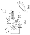
- Robot and press can be like those of Fig. 2 where there is shown a working area (working cell) 100 comprising an anthropomorphous robot 101 and a bending press 102 of a metal sheet 111 to be bent.
- the anthropomorphous robot 101 is provided with an arm 108 and with a grasping member 109 (suction cups, devices for grasping mechanically, pneumatically, magnetically and such like).
- the anthropomorphous robot 101 is capable of moving the metal sheet 111.
- the press 102 is provided with a bending tool 110 and with relevant abutment projections 113.
- the robot 101 and the press 102 are operatively connected to respective control units 103 and 104.
- the cell 100 also comprises a device 105 for feeding the metal sheets to be bent, a tilter 106 of the metal sheet and an unloading unit 107 of finished bent metal sheets 112, that in the particular case are of a rectangular shape, as shown in Fig. 3.
- a processing unit 120 consisting, for example, of a personal computer, the function of which will be illustrated later.
- the processing unit 120 could be incorporated into the control unit of the robot 101.
- the operating method of the present invention is based on a program (software algorithm) written in a preselected programming language and compiled and/or interpreted in a project computer, not shown.
- An executable program is obtained that is loaded into the processing unit 120.
- the method illustrated in Fig. 1, provides for a step of configuration of the working area 100 (block 1) comprising a step wherein parameters are established to identify the geometry of its components in space which, in the case exemplified, are the anthropomorphous robot 101, its grasping member 109, the bending press 102 and temporary accessory items such as the feeding unit 105, the tilter 106 and the unloading unit 107.
- the input data indicated earlier are called fixed because they are independent from the form and the dimensions of the metal sheet 111 to be bent. They are inserted or connected in a permanent manner in the executable program resident in the processing unit 120. The fixed input data are entered by an operator.
- the method also comprises a step of introduction of variable input data (block 2) in the processing unit 120 (Fig. 2).
- variable input data describe the shape of the metal sheet to be bent (111) and/or bent (112) in terms of height, length, angle and orientation of each bend; additional technological data related to the bending tools and to its accessories and the thickness of the metal sheet complete the information necessary for executing the bends.
- Such data consist essentially of
- the first three are geometric data, the last one is a technological data.
- variable input data can be represented indifferently by means of lines of definition, graphic objects, in the form of tables and such like.
- the variable input data are entered by an operator.
- variable input data are structured like a set of lines each of which describes in a very simple manner a characteristic such as, for example,
- variable input data For greater clarity, there is given hereinafter an example of a possible description of variable input data, with reference to the bent sheet with a rectangular shape of Fig. 3:
- the method also comprises a step of interpretation of the data for selecting the side to be bent, consisting of a sequence of analyses of the data (block 3.1), an examination of the direction of the bend with respect to a previous bend (block 3.2) and an examination of the orientation of the bend with respect to the previous bend (block 3.3).
- Two types of information are deduced from the writing/reading of the lines that represent the variable input data: geometry of the sheet to be bent and/or bent and sequence of execution of a working cycle.
- the geometry of the sheet to be bent and/or bent is represented by the values assumed by the codes related to the height of the bends (e.g. P20), to the bend angles (e.g. A90), to the length of the sides (e.g. 1.800) and so on.
- the sequence of execution of the cycle is deduced from the succession in which the lines that make up the variable input data are written.
- the wording "generic data" shown at the third branch of the selection fork (block 3.1) introduces the reading of a generic line of the variable input data.
- the succession of bends to be made proceeds according to the order of reading the lines with the code P.
- the sheet is tipped over (block 4.2) before the bend is executed. If the direction of the bend is the same as the preceding one the orientation of the bend with respect to the preceding one is examined (selection fork of block 3.3). If the orientation is the same the trajectory for the individual bend (block 4.3) is planned. If the orientation is different (a line with the side code L is encountered), a rotation of the sheet is introduced (block 4.4) so as to bend the sheet along a different side.
- the selection criteria (blocks 3.1, 3.2, 3.3) thus illustrated select the five physical components of the working area 100 (feeding unit 105, tilter 106, press 102, anthropomorphous robot 101, unloading unit 107) described in the configuration step by means of the fixed input data (block 1) so as to attribute the initial conditions for the automatic planning of the trajectories.
- the method provides for the automatic planning of the trajectories that join the components involved at the beginning and at the end of a working step (blocks 4.1; 4.2; 4.3; 4.4; 4.5).
- the identified trajectories can be:
- Each of these trajectories has a fixed initial point, a fixed final point and a path joining them defined by a succession of intermediate points.
- Each trajectory is constituted by a series of intermediate points planned so as to constrain the robot to move along pre-established paths.
- the "point”, in this context, is a manner of representing the Cartesian tern oriented in space.
- the automatic planning of the trajectories described takes place through an algorithm that arranges the points of the trajectory so that the mobile components and elements of the working area, such as the robots and the metal sheet, can move from the initial fixed component to the final fixed component without any mechanical interferences; the points forming the trajectory are those that serve so that the motion of the robot between two successive positions is predictable, that is to say that they are sufficient in number so that the joints of the robot move in a predictable manner.
- the fixed components (press, feeding, tilter, unloader) and the mobile components (robot) are in a univocal correspondence with the "points" that appear in the set of fixed input data in the configuration step (block 1).
- a further mobile element is the metal sheet to be bent, represented by the variable input data (block 2).
- the tilter instead of being a fixed component, may be mobile, in the sense that it executes rotations of the metal sheet.
- the method provides that, for every point of a planned trajectory, the following be calculated (block 5):
- the inverse kinematics is a mathematical transformation that place an oriented tern of Euclidean space (X, Y, Z, O, A, T) in relation to a set of vectors Z1, Z2, Z3, ... , Zn.
- Each vector Zi has as many components as there are axes of the robot; each component represents the linear or angular position that each axis can assume so as to reach the point (X, Y, Z, O, A, T).
- the method comprises a step of analysis of the sheet/machine interferences (block 6) for the selection of a suitable solution among those provided in the preceding step. Particularly, interferences sheet/robt, sheet/press, sheet/ feeding unit, sheet/tilter and/or sheet/unloading unit are examined.
- a logical-mathematical algorithm automatically identifies the most suitable solution, among the calculated representations, so as to eliminate the solutions that involve sheet/machine interferences, any out-of-strokes of the robot's axes and of the improper rotations ( ⁇ and ⁇ +/-360°) of the axes in passing from one point to the next.
- a simplified and ergonomic graphic representation is used that is capable of effectively visualising the sheet/machine interferences, the out-of-strokes and the improper rotations of the axes so as to quickly select (a few seconds), for all the points of the trajectory, the most suitable solution among those calculated for each point.
- This second (interactive) procedure can also be used for a quick visual check on the selections executed automatically by the first procedure.
- the method also comprises a step of generation of variable output data in a programming language that is specific to the control unit 103 of the robot (block 7).
- the results of the decisional and calculation algorithms are converted into output data valid for driving the robot 101 according to the syntax rules of the specific programming language.
- the converted data are the position vectors for the axes of the robot and a list with the names and the sequence of the parametric cycles to be executed.
- the names and the sequence of the cycles to be executed are in relation to the number of sides to be bent and to the number of bends for each side of the metal sheet.
- the method lastly comprises a step of generating the final output data in the form of fixed and parametric working cycles (block 8).
- the final output data are constituted by a set of elementary parametric cycles (feeding, rotation, bending, turning over, etc.) written according to the rules of syntax of the programming languages of the robots and specifically designed to receive the variable output data described above (block 7).
- the combination of the parametric cycles and of the variable data allow a complete production cycle, specific for each different type of metal sheet to be bent, to be obtained automatically.
- the bending press is enslaved to the robot and it integrates with it through control (output) signals and state (input) signals directly inserted into the parametric bending cycle. The result is a synchronized movement of the bending tool 110 and of the relevant abutment projections 113.
- the positions of the abutment projections 113 are obtained directly from the variable input data (block 2) and are automatically transferred by the processing unit 120 to the control unit of the press 104 so that the programming step of the metal sheet to be bent becomes completely automatic.
- the positions of the abutment projections 113 can be preset separately on the control unit 104 of the bending press.
- the result is a customised software algorithm, of the executable type, that once installed in the processing unit 120 of the working area, is in a position to receive as input the variable input data described earlier (block 2) and to provide as output the selected working cycle for bending the metal sheet and for moving the robot (block 8).
- the program defined in the processing unit 120 is transferred to the control unit of the robot 103 to drive the robot 101 and the bending press 102 for the immediate start of an automatic complete productive working cycle of a finished bent metal sheet 112 starting from the metal sheet to be bent 111.
- the executable program loaded in the processing unit 120 is changed once again by inserting the new variable input data (block 2) related to the new sheet to be bent and/or bent. In this way the program is updated so that it is then again inserted into the control unit 103of the robot.
- An important advantage of the invention consists in that a single robot interacts with all the components of the working area, i.e. the bending press, the feeding unit, the unloading unit, the tilter.
Landscapes
- Engineering & Computer Science (AREA)
- Mechanical Engineering (AREA)
- Robotics (AREA)
- Bending Of Plates, Rods, And Pipes (AREA)
- Manipulator (AREA)
- Press Drives And Press Lines (AREA)
- Numerical Control (AREA)
- Shaping Of Tube Ends By Bending Or Straightening (AREA)
Claims (36)
- Procédé opératoire pour région de travail (100) comprenant un robot (101) asservi à une cintreuse (102) destinée à usiner des feuilles métalliques (111), les feuilles métalliques (111) étant transmises par une unité d'alimentation (105), l'unité d'alimentation (105), le robot (101) et la cintreuse (102) ayant des positions géométriques préalablement fixées dans l'espace, le robot (101) ayant des bras (108) et un organe de saisie (109) capable de déplacer une feuille métallique (111) et raccordés pendant le fonctionnement à une unité de commande (103), le robot (101) étant anthropomorphe, caractérisé en ce que, pour le cintrage d'une feuille métallique déterminée (111) d'un côté au moins,a) des données fixes d'entrée sont détectées et comprennent des positions géométriques dans l'espace sous forme de données de forme et de termes cartésiens orientés sans recours à des techniques de CAO, des données de forme du robot (101) consistant aux dimensions des bras (108) et de l'organe de saisie (109),b) des données variables d'entrée sont sélectionnées et sont formées parreprésentées par des lignes de définition, des objets graphiques sous forme de tables, sans recours à des techniques de CAO,l'épaisseur de la feuille métallique (111),la hauteur, l'angle et la direction de chaque pli,la longueur et l'orientation de chaque pli,la position d'un outil de cintrage (110), etc) les données précitées sont traitées dans une unité de traitement (120) à l'aide d'un algorithme mettant en oeuvre les solutions du comportement cinématique inverse pour la création automatique de cycles d'alimentation, de cintrage et de déchargement de la feuille métallique (111),d) les cycles sont transférés à l'unité de commande (103) du robot (101) pour le pilotage du robot (101) et de la cintreuse (102) afin qu'ils commencent un cycle automatique complet d'usinage de production d'une feuille métallique cintrée finie (112) depuis la feuille métallique (111).
- Procédé opératoire selon la revendication 1, caractérisé en ce que les données fixes d'entrée comprennent une position préalablement fixée du robot (101).
- Procédé opératoire selon la revendication 1, caractérisé en ce que les données fixes d'entrée comprennent une position préalablement fixée de la cintreuse (102).
- Procédé opératoire selon la revendication 1, caractérisé en ce que les données fixes d'entrée comprennent une position préalablement fixée de l'unité d'alimentation (105) de la feuille métallique (111).
- Procédé opératoire selon la revendication 1, caractérisé en ce que les données fixes d'entrée comprennent une position préalablement fixée d'un organe de basculement (106) de la feuille métallique (111).
- Procédé opératoire selon la revendication 1, caractérisé en ce que les données fixes d'entrée comportent une position préalablement fixée d'une unité de déchargement (107) de la feuille métallique terminée (112).
- Procédé opératoire selon les revendications 1 à 6, caractérisé en ce que le point c) comprend une étape d'interprétation des données fixes variables d'entrée pour la sélection du côté à cintrer, l'interprétation étant constituée d'une séquence d'analyses de données (bloc 3.1) d'un examen de la direction du pli par rapport à un pli précédent (bloc 3.2) et d'un examen de l'orientation du pli par rapport au pli précédent (bloc 3.3) pour la déduction de deux types d'information : la configuration géométrique de la feuille à cintrer, et la séquence d'exécution du cycle d'usinage.
- Procédé opératoire selon la revendication 7, caractérisé en ce que les tables d'interprétation des données d'entrée variables et fixes reposent sur un algorithme de décision qui interprète les données et les divise pour identifier des étapes liées de travail d'un cycle d'usinage et les associer à un élément constituant formé par un élément choisi parmi le robot (101), la cintreuse (102), l'organe de pivotement (106), l'unité d'alimentation (105) et l'unité de déchargement (107).
- Procédé opératoire selon la revendication 8, caractérisé en ce que, pour les étapes d'usinage, les trajectoires qui relient les éléments constituants mis en oeuvre au début et à la fin de l'étape d'usinage (bloc 4.1, 4.2, 4.3, 4.4, 4.5) sont automatiquement planifiées.
- Procédé opératoire selon la revendication 9, caractérisé en ce que les trajectoires planifiées sont constituées parune trajectoire allant de l'unité d'alimentation (105) à la cintreuse (102) (bloc 4.1),une trajectoire allant de la cintreuse (102) à l'organe de pivotement (106) et inversement (bloc 4.2),une trajectoire allant de la cintreuse (102) à la cintreuse (102) pour le cintrage de la feuille métallique (111) (bloc 4.3),une trajectoire allant de la cintreuse (102) à la cintreuse (102) et destinée à faire tourner la feuille métallique (111) (bloc 4.4), etune trajectoire allant de la cintreuse (102) à l'unité de déchargement (107) (bloc 4.5).
- Procédé opératoire selon la revendication 10, caractérisé en ce que, pour chaque point de l'une des trajectoires planifiées, un calcul est réalisé (bloc 5) pour :des solutions du comportement cinématique inverse pour le bras (108) du robot (101), etdes associations entre la feuille métallique et un ou plusieurs éléments parmi le robot (101), la cintreuse (102), l'unité d'alimentation (105), l'organe pivotant (106), et l'unité de déchargement (107) pour chaque solution déterminée.
- Procédé opératoire selon la revendication 11, caractérisé en ce qu'il comprend une étape d'analyse des interférences (bloc 6) entre la feuille métallique (111) et un ou plusieurs éléments parmi le robot (101), la cintreuse (102), l'unité d'alimentation (105), l'organ pivotant (106) et l'unité de déchargement (107) afin qu'une solution convenable soit automatiquement sélectionnée parmi les solutions trouvées.
- Procédé opératoire selon la revendication 11, caractérisé en ce qu'il comprend une étape de représentation graphique capable de visualiser des interférences feuille-machine, les fins de course et les rotations erronées des axes du robot (101) pour la sélection, en tous les points de la trajectoire, de la solution la plus convenable parmi celles qui sont calculées pour chaque point.
- Procédé opératoire selon la revendication 12 ou 13, caractérisé en ce qu'il comprend une étape de création de données variables de sortie (bloc 7) telles que les résultats des algorithmes de décision et de calcul sont transformés en données variables de sortie dans un langage spécifique de programmation de l'unité de commande (103) du robot, les données transformées de sortie étant constituées par des vecteurs de position des axes du robot (101) et par une liste ayant des noms et une séquence de cycles paramétriques à exécuter en fonction du nombre de côtés à cintrer et du nombre de plis de chaque côté de la feuille métallique (111) à cintrer.
- Procédé opératoire selon la revendication 14, caractérisé en ce qu'il comprend une étape de création de données finales de sortie (bloc 8) telles que des données de sortie sont créées sous forme de cycles fixes et paramétriques d'usinage, les données finales de sortie étant formées par un ensemble de cycles élémentaires paramétriques liés à l'alimentation, la rotation, le cintrage, le retournement et le déchargement, les cycles élémentaires étant écrits avec un langage spécifique destinés à l'unité de commande (103) du robot et étant destiné spécifiquement à recevoir les données variables de sortie afin que la combinaison des cycles paramétriques et des données variables de sortie permette l'obtention automatique du cycle complet de production spécifique de la feuille métallique (111) à cintrer.
- Procédé opératoire selon les revendications 1 et 15, caractérisé en ce que la cintreuse (102) est asservie au robot (101) et est intégrée à celui-ci par des signaux de pilotage et des signaux d'état insérés directement dans le cycle de cintrage paramétrique, pour l'obtention d'un déplacement synchronisé d'un outil de cintrage (110) et de saillies correspondantes de butée (113) de la cintreuse (102).
- Procédé opératoire selon les revendications 1 et 16, caractérisé en ce que les positions des saillies de butée (113) sont directement obtenues à partir des données variables d'entrée et transférées automatiquement d'une unité de traitement (120) à une unité de commande (104) de la cintreuse (102).
- Procédé opératoire selon les revendications 1 et 16, caractérisé en ce que les positions des saillies de butée (113) sont préréglées dans une unité de commande (104) de la cintreuse (102).
- Dispositif comprenant un robot (101) asservi à une cintreuse (102) pour l'usinage de feuilles métalliques (111), les feuilles métalliques (111) étant transmises par une unité d'alimentation (105), une unité d'alimentation (105), le robot (101) et la cintreuse (102) ayant des positions géométriques préalablement fixées dans l'espace, le robot (101) ayant des bras (108) et un organe de saisie (109) qui peut déplacer une feuille métallique (111) et qui est raccordé pendant le fonctionnement à une unité de commande (103), le robot (101) étant anthropomorphe, caractérisé en ce que l'unité de commande (103) est chargée d'un programme exécutable sur ordinateur grâce auquel elle peut fonctionner par mise en oeuvre d'un procédé opératoire dans lequel, pour une feuille métallique déterminée (111) à cintrer d'un côté au moins,a) des données fixes d'entrée sont délectées et comprennent des positions géométriques dans l'espace sous forme de données de forme et de termes cartésiens orientés sans recours à des techniques de CAO, des données de forme du robot (101) consistant aux dimensions des bras (108) et de l'organe de saisie (109),b) des données variables d'entrée sont sélectionnées et sont formées parreprésentées par des lignes de définition, des objets graphiques sous forme de tables, sans recours à des techniques de CAO,l'épaisseur de la feuille métallique (111),la hauteur, l'angle et la direction de chaque pli,la longueur et l'orientation de chaque pli,la position d'un outil de cintrage (110), etc) les données précitées sont traitées dans une unité de traitement (120) à l'aide d'un algorithme mettant en oeuvre les solutions du comportement cinématique inverse pour la création automatique de cycles d'alimentation, de cintrage et de déchargement de la feuille métallique (111),d) les cycles sont transférés à l'unité de commande (103) du robot (101) pour le pilotage du robot (101) et de la cintreuse (102) afin qu'ils commencent un cycle automatique complet d'usinage de production d'une feuille métallique cintrée finie (112) depuis la feuille métallique (111).
- Dispositif (101) selon la revendication 19, caractérisé en ce que, dans le procédé, les données fixes d'entrée comprennent une position préalablement fixée du robot (101).
- Dispositif (101) selon la revendication 19, caractérisé en ce que, dans le procédé, les données fixes d'entrée comportent une position préalablement fixée de la cintreuse (102).
- Dispositif (101) selon la revendication 19, caractérisé en ce que, dans le procédé, les données fixes d'entrée comportent une position préalablement fixée de l'unité d'alimentation (105) de la feuille métallique (111).
- Dispositif (101) selon la revendication 19, caractérisé en ce que, dans le procédé, les données fixes d'entrée comportent une position préalablement fixée d'un organe pivotant (106) de la feuille métallique (111).
- Dispositif (101) selon la revendication 19, caractérisé en ce que, dans le procédé, les données fixes d'entrée comportent une position préalablement fixée d'une unité de déchargement (107) de la feuille métallique terminée (112).
- Dispositif (101) selon les revendications 19 à 24, caractérisé en ce que, dans le procédé, le point c) comprend une étape d'interprétation des données fixes variables d'entrée pour la sélection du côté à cintrer, l'interprétation étant constituée d'une séquence d'analyses de données (bloc 3.1) d'un examen de la direction du pli par rapport à un pli précédent (bloc 3.2) et d'un examen de l'orientation du pli par rapport au pli précédent (bloc 3.3) pour la déduction de deux types d'information : la configuration géométrique de la feuille à cintrer, et la séquence d'exécution du cycle d'usinage.
- Dispositif (101) selon la revendication 25, caractérisé en ce que, dans le procédé, les tables d'interprétation des données d'entrée variables et fixes reposent sur un algorithme de décision qui interprète les données et les divise pour identifier des étapes liées de travail d'un cycle d'usinage et les associer à un élément constituant formé par un élément choisi parmi le robot (101), la cintreuse (102), l'organe de pivotement (106), l'unité d'alimentation (105) et l'unité de déchargement (107).
- Dispositif (101) selon la revendication 26, caractérisé en ce que, dans le procédé, pour les étapes d'usinage, les trajectoires qui relient les éléments constituants mis en oeuvre au début et à la fin de l'étape d'usinage (bloc 4.1, 4.2, 4.3, 4.4, 4.5) sont automatiquement planifiées.
- Dispositif (101) selon la revendication 27, caractérisé en ce que, dans le procédé, les trajectoires planifiées sont constituées parune trajectoire allant de l'unité d'alimentation (105) à la cintreuse (102) (bloc 4.1),une trajectoire allant de la cintreuse (102) à l'organe de pivotement (106) et inversement (bloc 4.2),une trajectoire allant de la cintreuse (102) à la cintreuse (102) pour le cintrage de la feuille métallique (111) (bloc 4.3),une trajectoire allant de la cintreuse (102) à la cintreuse (102) et destinée à faire tourner la feuille métallique (111) (bloc 4.4), etune trajectoire allant de la cintreuse (102) à l'unité de déchargement (107) (bloc 4.5).
- Dispositif (101) selon la revendication 28, caractérisé en ce que, dans le procédé, pour chaque point de l'une des trajectoires planifiées, un calcul est réalisé (bloc 5) pour :des solutions du comportement cinématique inverse pour le bras (108) du robot (101), etdes associations entre la feuille métallique et un ou plusieurs éléments parmi le robot (101), la cintreuse (102), l'unité d'alimentation (105), l'organe pivotant (106), et l'unité de déchargement (107) pour chaque solution déterminée.
- Dispositif (101) selon la revendication 29, caractérisé en ce que le procédé comprend une étape d'analyse des interférences (bloc 6) entre la feuille métallique (111) et un ou plusieurs éléments parmi le robot (101), la cintreuse (102), l'unité d'alimentation (105), l'organe pivotant (106) et l'unité de déchargement (107) afin qu'une solution convenable soit automatiquement sélectionnée parmi les solutions trouvées.
- Dispositif (101) selon la revendication 29, caractérisé en ce que le procédé comprend une étape de représentation graphique capable de visualiser des interférences feuille-machine, les fins de course et les rotations erronées des axes du robot (101) pour la sélection, en tous les points de la trajectoire, de la solution la plus convenable parmi celles qui sont calculées pour chaque point.
- Dispositif (101) selon la revendication 30 ou 31, caractérisé en ce que le procédés comprend une étape de création de données variables de sortie (bloc 7) telles que les résultats des algorithmes de décision et de calcul sont transformés en données variables de sortie dans un langage spécifique de programmation de l'unité de commande (103) du robot, les données transformées de sortie étant constituées par des vecteurs de position des axes du robot (101) et par une liste ayant des noms et une séquence de cycles paramétriques à exécuter en fonction du nombre de côtés à cintrer et du nombre de plis de chaque côté de la feuille métallique (111) à cintrer.
- Dispositif (101) selon la revendication 32, caractérisé en ce que le procédé comprend une étape de création de données finales de sortie (bloc 8) telles que des données de sortie sont créées sous forme de cycles fixes et paramétriques d'usinage, les données finales de sortie étant formées par un ensemble de cycles élémentaires paramétriques liés à l'alimentation, la rotation, le cintrage, le retournement et le déchargement, les cycles élémentaires étant écrits avec un langage spécifique destinés à l'unité de commande (103) du robot et étant destiné spécifiquement à recevoir les données variables de sortie afin que la combinaison des cycles paramétriques et des données variables de sortie permette l'obtention automatique du cycle complet de production spécifique de la feuille métallique (111) à cintrer.
- Dispositif (101) selon les revendications 19 et 33, caractérisé en ce que, dans le procédé, la cintreuse (102) est asservie au robot (101) et est intégrée à celui-ci par des signaux de pilotage et des signaux d'état insérés directement dans le cycle de cintrage paramétrique, pour l'obtention d'un déplacement synchronisé d'un outil de cintrage (110) et de saillies correspondantes de butée (113) de la cintreuse (102).
- Dispositif (101) selon les revendications 19 et 34, caractérisé en ce que, dans le procédé, les positions des saillies de butée (113) sont directement obtenues à partir des données variables d'entrée et transférées automatiquement d'une unité de traitement (120) à une unité de commande (104) de la cintreuse (102).
- Dispositif (101) selon les revendications 19 et 34, caractérisé en ce que, dans le procédé, les positions des saillies de butée (113) sont préréglées dans une unité de commande (104) de la cintreuse (102).
Applications Claiming Priority (2)
| Application Number | Priority Date | Filing Date | Title |
|---|---|---|---|
| IT96MI000982A IT1283019B1 (it) | 1996-05-16 | 1996-05-16 | Metodo di gestione di un'isola di lavoro comprendente un robot asser- vito ad una pressa piegatrice per lavorazione di fogli di lamiera. |
| ITMI960982 | 1996-05-16 |
Publications (2)
| Publication Number | Publication Date |
|---|---|
| EP0807497A1 EP0807497A1 (fr) | 1997-11-19 |
| EP0807497B1 true EP0807497B1 (fr) | 2002-09-18 |
Family
ID=11374271
Family Applications (1)
| Application Number | Title | Priority Date | Filing Date |
|---|---|---|---|
| EP97201416A Expired - Lifetime EP0807497B1 (fr) | 1996-05-16 | 1997-05-10 | Méthode de fonctionnement pour un espace de travail comprenant un robot asservi à une presse à cintrer pour traiter des tôles métalliques |
Country Status (11)
| Country | Link |
|---|---|
| US (1) | US5988855A (fr) |
| EP (1) | EP0807497B1 (fr) |
| JP (1) | JP4130703B2 (fr) |
| KR (1) | KR970073892A (fr) |
| AT (1) | ATE224261T1 (fr) |
| CA (1) | CA2205162C (fr) |
| DE (1) | DE69715508T2 (fr) |
| DK (1) | DK0807497T3 (fr) |
| ES (1) | ES2181982T3 (fr) |
| IT (1) | IT1283019B1 (fr) |
| PT (1) | PT807497E (fr) |
Cited By (1)
| Publication number | Priority date | Publication date | Assignee | Title |
|---|---|---|---|---|
| DE10338170A1 (de) * | 2003-08-20 | 2005-03-17 | Edag Engineering + Design Ag | Rollfalzvorrichtung |
Families Citing this family (30)
| Publication number | Priority date | Publication date | Assignee | Title |
|---|---|---|---|---|
| US6968375B1 (en) * | 1997-03-28 | 2005-11-22 | Health Hero Network, Inc. | Networked system for interactive communication and remote monitoring of individuals |
| US7624028B1 (en) | 1992-11-17 | 2009-11-24 | Health Hero Network, Inc. | Remote health monitoring and maintenance system |
| IT1284548B1 (it) * | 1996-09-18 | 1998-05-21 | Salvagnini Italia Spa | Metodo per trasporto di fogli di lamiera in un'isola di lavoro comprendente una macchina utensile e un robot |
| IT1294998B1 (it) * | 1997-09-09 | 1999-04-27 | Salvagnini Italia Spa | Procedimento per la generazione automatica di una sequenza di comandi per macchina piegatrice di fogli di lamiera |
| NL1010359C2 (nl) * | 1998-10-20 | 1999-10-11 | Delem B V | Werkwijze voor het bepalen van een gereedschapconfiguratie. |
| IT1313346B1 (it) * | 1999-09-06 | 2002-07-23 | Abb Ricerca Spa | Metodo per eseguire la programmazione fuori linea di un robotindustriale. |
| US6269677B1 (en) | 1999-12-28 | 2001-08-07 | Abb T&D Technology Ltd. | Press brake back gauge finger |
| EP1763421A1 (fr) * | 2004-03-16 | 2007-03-21 | Abb Ab | Systeme de manipulateurs et sa methode de commande |
| DE602005017301D1 (de) * | 2004-10-25 | 2009-12-03 | Alcoa Inc | Virtuelle programmierung von formteilbahnen |
| SE0402891D0 (sv) * | 2004-11-26 | 2004-11-26 | Abb Ab | A system and a method for controlling movements of an industrial robot |
| US20070299556A1 (en) * | 2005-11-10 | 2007-12-27 | Hugo Salamanca | Robot system and method for scrap bundling in metal smelting and refining processes |
| US7746018B2 (en) | 2005-11-10 | 2010-06-29 | MI Robotic Solutions | Robot system and method for reposition and/or removal of base plates from cathode stripping machines in electrometallurgical processes |
| JP4271232B2 (ja) | 2006-12-20 | 2009-06-03 | ファナック株式会社 | ロボットのオフラインプログラミングを実行するための装置、方法、プログラム及び記録媒体 |
| CN101572029B (zh) * | 2008-04-28 | 2012-01-25 | 鸿富锦精密工业(深圳)有限公司 | 机器人板材折弯模拟系统及方法 |
| US8285413B1 (en) * | 2009-03-29 | 2012-10-09 | International Training Institute for the Sheet Metal and Air Conditioning Industry | Sheet metal fabrication system |
| ITMO20090154A1 (it) * | 2009-06-12 | 2010-12-13 | Piercarlo Bonomi | Attrezzatura per la lavorazione meccanica su pezzi fusi o stampati, particolarmente per la sbavatura, la molatura e il taglio dei canali di colata di pezzi in ghisa, acciaio o simili |
| JP4910097B2 (ja) | 2011-07-25 | 2012-04-04 | コージ産業株式会社 | 棚装置 |
| JP5160700B1 (ja) * | 2011-08-24 | 2013-03-13 | ヤマザキマザック株式会社 | Nc工作機械システム |
| CN104369128A (zh) * | 2013-08-17 | 2015-02-25 | 江苏卡威汽车工业集团有限公司 | 一种汽车左右侧外板总成夹具 |
| CN104625992B (zh) * | 2013-11-06 | 2017-12-05 | 富泰华工业(深圳)有限公司 | 定位装置 |
| JP6019149B2 (ja) * | 2015-02-19 | 2016-11-02 | 株式会社アマダホールディングス | ベンディングロボット及びワーク検出方法 |
| CN106141954B (zh) * | 2016-07-26 | 2017-11-24 | 北京工业大学 | 一种基于振动的能量采集对边简支结构发电装置的夹具 |
| CN106272166B (zh) * | 2016-09-26 | 2018-05-29 | 南昌航空大学 | 一种飞机长梁多工位自动夹具 |
| CN106514511B (zh) * | 2016-11-29 | 2018-03-27 | 延锋伟世通电子科技(南京)有限公司 | 一种汽车导航屏模组装配用定位工装 |
| JP6932380B2 (ja) * | 2018-09-05 | 2021-09-08 | 株式会社ウエーブ | 箔押し機用給排紙方法および装置 |
| DE102018124671B4 (de) * | 2018-10-06 | 2020-11-26 | Bystronic Laser Ag | Verfahren und Vorrichtung zur Erstellung eines Robotersteuerprogramms |
| WO2021028011A1 (fr) * | 2019-08-09 | 2021-02-18 | Quintus Technologies Ab | Système et procédé de manipulation et de traitement par pression isostatique d'une charge |
| CN110548783B (zh) * | 2019-09-14 | 2020-08-11 | 江苏省健尔康医用敷料有限公司 | 医用纱布纺织机翻转滑拨板的自动化生产装置 |
| KR102432978B1 (ko) * | 2020-11-25 | 2022-08-18 | 에코캡 주식회사 | 메탈피시비 성형장치 및 방법 |
| CN116174536A (zh) * | 2022-11-24 | 2023-05-30 | 江苏亚威机床股份有限公司 | 一种用于折弯窄件的前推后挡机器人折弯单元 |
Family Cites Families (16)
| Publication number | Priority date | Publication date | Assignee | Title |
|---|---|---|---|---|
| US4430879A (en) * | 1981-06-12 | 1984-02-14 | Hurco Manufacturing Company, Inc. | Apparatus for controlling a press brake |
| JPS59189415A (ja) * | 1983-04-13 | 1984-10-27 | Hitachi Ltd | 工業用ロボツトの動作教示方法および装置 |
| DE3407445A1 (de) * | 1984-02-29 | 1985-09-12 | Siemens AG, 1000 Berlin und 8000 München | Positioniervorrichtung fuer automatisch bestueckbare biegepresse |
| US4998206A (en) * | 1988-07-29 | 1991-03-05 | The Boeing Company | Automated method and apparatus for fabricating sheet metal parts and the like using multiple manufacturing stations |
| DE3902149C2 (de) * | 1988-01-29 | 2000-05-18 | Amada Co | Biegeeinrichtung und Verfahren zum Positionieren von Werkstücken in einer Blechbiegeeinrichtung |
| US5307282A (en) * | 1989-09-22 | 1994-04-26 | Hewlett-Packard Company | Method of computer-aided prediction of collisions between objects including fabrication tools and parts to be fabricated |
| KR0160452B1 (ko) * | 1989-12-18 | 1999-01-15 | 아마다 미쯔아끼 | 금속시트 굽힘설비용 로보트 매니플레이터의 제어장치 |
| US5642291A (en) * | 1989-12-22 | 1997-06-24 | Amada Company, Limited Of Japan | System for creating command and control signals for a complete operating cycle of a robot manipulator device of a sheet metal bending installation by simulating the operating environment |
| IT1237740B (it) * | 1989-12-22 | 1993-06-15 | Prima Ind Spa | Sistema per la creazione di segnali di comando e di controllo per un ciclo operativo completo di un dispositivo manipolatore robotizzato di un impianto di piegatura di lamiere, tramite la simulazione dello ambiente operativo. |
| US5345806A (en) * | 1989-12-29 | 1994-09-13 | Amada Company, Limited | Device for manipulating sheet metal pieces |
| IT1237750B (it) * | 1989-12-29 | 1993-06-15 | Prima Ind Spa | Procedimento di piegatura di una lamiera |
| US5347616A (en) * | 1991-01-28 | 1994-09-13 | Tsubakimoto Chain Co. | Method of controlling position and attitude of working robot and its manipulator and apparatus thereof |
| JP3515137B2 (ja) * | 1992-11-17 | 2004-04-05 | 株式会社アマダ | 曲げロボットの制御方法 |
| US5835684A (en) * | 1994-11-09 | 1998-11-10 | Amada Company, Ltd. | Method for planning/controlling robot motion |
| JP4221061B2 (ja) * | 1994-11-09 | 2009-02-12 | 株式会社アマダ | 板金曲げ計画の作成・実行用知能システム |
| JP3334400B2 (ja) * | 1995-02-02 | 2002-10-15 | トヨタ自動車株式会社 | 仕掛計画立案装置 |
-
1996
- 1996-05-16 IT IT96MI000982A patent/IT1283019B1/it active IP Right Grant
-
1997
- 1997-05-10 DK DK97201416T patent/DK0807497T3/da active
- 1997-05-10 PT PT97201416T patent/PT807497E/pt unknown
- 1997-05-10 DE DE69715508T patent/DE69715508T2/de not_active Expired - Lifetime
- 1997-05-10 ES ES97201416T patent/ES2181982T3/es not_active Expired - Lifetime
- 1997-05-10 EP EP97201416A patent/EP0807497B1/fr not_active Expired - Lifetime
- 1997-05-10 AT AT97201416T patent/ATE224261T1/de active
- 1997-05-12 CA CA002205162A patent/CA2205162C/fr not_active Expired - Fee Related
- 1997-05-15 US US08/856,683 patent/US5988855A/en not_active Expired - Lifetime
- 1997-05-16 KR KR1019970018862A patent/KR970073892A/ko not_active Ceased
- 1997-05-16 JP JP12693197A patent/JP4130703B2/ja not_active Expired - Fee Related
Cited By (2)
| Publication number | Priority date | Publication date | Assignee | Title |
|---|---|---|---|---|
| DE10338170A1 (de) * | 2003-08-20 | 2005-03-17 | Edag Engineering + Design Ag | Rollfalzvorrichtung |
| DE10338170B4 (de) * | 2003-08-20 | 2005-12-29 | Edag Engineering + Design Ag | Rollfalzvorrichtung und deren Verwendung |
Also Published As
| Publication number | Publication date |
|---|---|
| EP0807497A1 (fr) | 1997-11-19 |
| DE69715508T2 (de) | 2003-05-28 |
| DK0807497T3 (da) | 2003-01-06 |
| JP4130703B2 (ja) | 2008-08-06 |
| IT1283019B1 (it) | 1998-04-03 |
| US5988855A (en) | 1999-11-23 |
| ES2181982T3 (es) | 2003-03-01 |
| PT807497E (pt) | 2003-02-28 |
| ITMI960982A0 (fr) | 1996-05-16 |
| JPH10111707A (ja) | 1998-04-28 |
| KR970073892A (ko) | 1997-12-10 |
| ITMI960982A1 (it) | 1997-11-16 |
| DE69715508D1 (de) | 2002-10-24 |
| CA2205162C (fr) | 2006-08-15 |
| ATE224261T1 (de) | 2002-10-15 |
| CA2205162A1 (fr) | 1997-11-16 |
Similar Documents
| Publication | Publication Date | Title |
|---|---|---|
| EP0807497B1 (fr) | Méthode de fonctionnement pour un espace de travail comprenant un robot asservi à une presse à cintrer pour traiter des tôles métalliques | |
| US5511147A (en) | Graphical interface for robot | |
| US9207668B2 (en) | Method of and apparatus for automated path learning | |
| JPH09509513A (ja) | ロボットの運動を計画し制御する方法 | |
| EP0830921B1 (fr) | Méthode de manipulation de feuilles de métal dans une aire de travail comprenant une machine-outil et un robot | |
| FI112922B (fi) | Menetelmä työstökonesolun ohjauksessa | |
| EP2666064B1 (fr) | Méthode d'apprentissage d'un mouvement de robot | |
| JPH10124130A (ja) | 組立装置 | |
| Carvalho et al. | Off-line programming of flexible welding manufacturing cells | |
| EP0086848A1 (fr) | Methode d'enseignement d'operations a un robot | |
| Lee et al. | ROBOSIM: a CAD-based off-line programming and analysis system for robotic manipulators | |
| Lindberget | Automatic generation of robot targets: A first step towards a flexible robotic solution for cutting customized mesh tray | |
| Neto et al. | 3D CAD-based robot programming for the SME shop-floor | |
| Stobart | Geometric tools for the off-line programming of robots | |
| US20030093165A1 (en) | Programming method for creating a control program of an industrial machine | |
| da Rosa et al. | Design and Implementation of a Platform for Controlling the Mentor Robotic Arm | |
| Angermüller et al. | Off‐line programming and simultation of flexible assembly | |
| Bennaton | Integrated systems for off‐line programming | |
| Wloka | Graphical Simulation of the Factory of the Future | |
| Earl et al. | Sheet Metal Enclosure Manufacture—A Flexible System | |
| Hassan | Designing and Implementation of a New Programming Technique for the Control of Industrial Robot | |
| Paul | The early stages of robotics | |
| Choi et al. | Performance Evaluation of An Intuitive Robot Teach Method Using a Force/moment Direction Sensor | |
| JPH03118921A (ja) | プレスブレーキシステムのロボットプログラム作成装置 | |
| Hill et al. | Kinematic Simulation of Robotic Systems |
Legal Events
| Date | Code | Title | Description |
|---|---|---|---|
| PUAI | Public reference made under article 153(3) epc to a published international application that has entered the european phase |
Free format text: ORIGINAL CODE: 0009012 |
|
| AK | Designated contracting states |
Kind code of ref document: A1 Designated state(s): AT BE CH DE DK ES FI FR GB GR IE IT LI LU NL PT SE |
|
| 17P | Request for examination filed |
Effective date: 19980508 |
|
| 17Q | First examination report despatched |
Effective date: 19990430 |
|
| GRAG | Despatch of communication of intention to grant |
Free format text: ORIGINAL CODE: EPIDOS AGRA |
|
| GRAG | Despatch of communication of intention to grant |
Free format text: ORIGINAL CODE: EPIDOS AGRA |
|
| GRAH | Despatch of communication of intention to grant a patent |
Free format text: ORIGINAL CODE: EPIDOS IGRA |
|
| GRAH | Despatch of communication of intention to grant a patent |
Free format text: ORIGINAL CODE: EPIDOS IGRA |
|
| GRAH | Despatch of communication of intention to grant a patent |
Free format text: ORIGINAL CODE: EPIDOS IGRA |
|
| GRAA | (expected) grant |
Free format text: ORIGINAL CODE: 0009210 |
|
| AK | Designated contracting states |
Kind code of ref document: B1 Designated state(s): AT BE CH DE DK ES FI FR GB GR IE IT LI LU NL PT SE |
|
| PG25 | Lapsed in a contracting state [announced via postgrant information from national office to epo] |
Ref country code: GR Free format text: LAPSE BECAUSE OF FAILURE TO SUBMIT A TRANSLATION OF THE DESCRIPTION OR TO PAY THE FEE WITHIN THE PRESCRIBED TIME-LIMIT Effective date: 20020918 |
|
| REF | Corresponds to: |
Ref document number: 224261 Country of ref document: AT Date of ref document: 20021015 Kind code of ref document: T |
|
| REG | Reference to a national code |
Ref country code: GB Ref legal event code: FG4D |
|
| REG | Reference to a national code |
Ref country code: CH Ref legal event code: EP |
|
| REG | Reference to a national code |
Ref country code: IE Ref legal event code: FG4D |
|
| REF | Corresponds to: |
Ref document number: 69715508 Country of ref document: DE Date of ref document: 20021024 |
|
| REG | Reference to a national code |
Ref country code: DK Ref legal event code: T3 |
|
| REG | Reference to a national code |
Ref country code: CH Ref legal event code: NV Representative=s name: E. BLUM & CO. PATENTANWAELTE |
|
| REG | Reference to a national code |
Ref country code: PT Ref legal event code: SC4A Free format text: AVAILABILITY OF NATIONAL TRANSLATION Effective date: 20021217 |
|
| REG | Reference to a national code |
Ref country code: ES Ref legal event code: FG2A Ref document number: 2181982 Country of ref document: ES Kind code of ref document: T3 |
|
| ET | Fr: translation filed | ||
| PG25 | Lapsed in a contracting state [announced via postgrant information from national office to epo] |
Ref country code: LU Free format text: LAPSE BECAUSE OF NON-PAYMENT OF DUE FEES Effective date: 20030510 |
|
| PG25 | Lapsed in a contracting state [announced via postgrant information from national office to epo] |
Ref country code: IE Free format text: LAPSE BECAUSE OF NON-PAYMENT OF DUE FEES Effective date: 20030512 |
|
| PLBE | No opposition filed within time limit |
Free format text: ORIGINAL CODE: 0009261 |
|
| STAA | Information on the status of an ep patent application or granted ep patent |
Free format text: STATUS: NO OPPOSITION FILED WITHIN TIME LIMIT |
|
| 26N | No opposition filed |
Effective date: 20030619 |
|
| REG | Reference to a national code |
Ref country code: IE Ref legal event code: MM4A |
|
| REG | Reference to a national code |
Ref country code: CH Ref legal event code: PFA Owner name: SALVAGNINI ITALIA S.P.A. Free format text: SALVAGNINI ITALIA S.P.A.#VIA MONTICELLO DI FARA, 42#I-36040 SAREGO (VICENZA) (IT) -TRANSFER TO- SALVAGNINI ITALIA S.P.A.#VIA MONTICELLO DI FARA, 42#I-36040 SAREGO (VICENZA) (IT) |
|
| PGFP | Annual fee paid to national office [announced via postgrant information from national office to epo] |
Ref country code: ES Payment date: 20120508 Year of fee payment: 16 |
|
| PGFP | Annual fee paid to national office [announced via postgrant information from national office to epo] |
Ref country code: AT Payment date: 20120420 Year of fee payment: 16 |
|
| PGFP | Annual fee paid to national office [announced via postgrant information from national office to epo] |
Ref country code: SE Payment date: 20130425 Year of fee payment: 17 Ref country code: CH Payment date: 20130424 Year of fee payment: 17 Ref country code: GB Payment date: 20130424 Year of fee payment: 17 Ref country code: DE Payment date: 20130423 Year of fee payment: 17 Ref country code: BE Payment date: 20130424 Year of fee payment: 17 Ref country code: DK Payment date: 20130424 Year of fee payment: 17 |
|
| PGFP | Annual fee paid to national office [announced via postgrant information from national office to epo] |
Ref country code: NL Payment date: 20130424 Year of fee payment: 17 Ref country code: FI Payment date: 20130423 Year of fee payment: 17 Ref country code: IT Payment date: 20130423 Year of fee payment: 17 Ref country code: PT Payment date: 20130503 Year of fee payment: 17 Ref country code: FR Payment date: 20130626 Year of fee payment: 17 |
|
| REG | Reference to a national code |
Ref country code: PT Ref legal event code: MM4A Free format text: LAPSE DUE TO NON-PAYMENT OF FEES Effective date: 20141110 |
|
| REG | Reference to a national code |
Ref country code: DE Ref legal event code: R119 Ref document number: 69715508 Country of ref document: DE |
|
| REG | Reference to a national code |
Ref country code: NL Ref legal event code: V1 Effective date: 20141201 |
|
| REG | Reference to a national code |
Ref country code: CH Ref legal event code: PL |
|
| REG | Reference to a national code |
Ref country code: DK Ref legal event code: EBP Effective date: 20140531 |
|
| REG | Reference to a national code |
Ref country code: AT Ref legal event code: MM01 Ref document number: 224261 Country of ref document: AT Kind code of ref document: T Effective date: 20140510 |
|
| GBPC | Gb: european patent ceased through non-payment of renewal fee |
Effective date: 20140510 |
|
| PG25 | Lapsed in a contracting state [announced via postgrant information from national office to epo] |
Ref country code: FI Free format text: LAPSE BECAUSE OF NON-PAYMENT OF DUE FEES Effective date: 20140510 Ref country code: LI Free format text: LAPSE BECAUSE OF NON-PAYMENT OF DUE FEES Effective date: 20140531 Ref country code: PT Free format text: LAPSE BECAUSE OF NON-PAYMENT OF DUE FEES Effective date: 20141110 Ref country code: CH Free format text: LAPSE BECAUSE OF NON-PAYMENT OF DUE FEES Effective date: 20140531 Ref country code: SE Free format text: LAPSE BECAUSE OF NON-PAYMENT OF DUE FEES Effective date: 20140511 |
|
| REG | Reference to a national code |
Ref country code: SE Ref legal event code: EUG |
|
| PG25 | Lapsed in a contracting state [announced via postgrant information from national office to epo] |
Ref country code: NL Free format text: LAPSE BECAUSE OF NON-PAYMENT OF DUE FEES Effective date: 20141201 Ref country code: AT Free format text: LAPSE BECAUSE OF NON-PAYMENT OF DUE FEES Effective date: 20140510 |
|
| REG | Reference to a national code |
Ref country code: FR Ref legal event code: ST Effective date: 20150130 |
|
| REG | Reference to a national code |
Ref country code: DE Ref legal event code: R119 Ref document number: 69715508 Country of ref document: DE Effective date: 20141202 |
|
| PG25 | Lapsed in a contracting state [announced via postgrant information from national office to epo] |
Ref country code: IT Free format text: LAPSE BECAUSE OF NON-PAYMENT OF DUE FEES Effective date: 20140510 Ref country code: DK Free format text: LAPSE BECAUSE OF NON-PAYMENT OF DUE FEES Effective date: 20140531 Ref country code: DE Free format text: LAPSE BECAUSE OF NON-PAYMENT OF DUE FEES Effective date: 20141202 |
|
| PG25 | Lapsed in a contracting state [announced via postgrant information from national office to epo] |
Ref country code: FR Free format text: LAPSE BECAUSE OF NON-PAYMENT OF DUE FEES Effective date: 20140602 Ref country code: GB Free format text: LAPSE BECAUSE OF NON-PAYMENT OF DUE FEES Effective date: 20140510 |
|
| REG | Reference to a national code |
Ref country code: ES Ref legal event code: FD2A Effective date: 20150629 |
|
| PG25 | Lapsed in a contracting state [announced via postgrant information from national office to epo] |
Ref country code: ES Free format text: LAPSE BECAUSE OF NON-PAYMENT OF DUE FEES Effective date: 20140511 |
|
| PG25 | Lapsed in a contracting state [announced via postgrant information from national office to epo] |
Ref country code: BE Free format text: LAPSE BECAUSE OF NON-PAYMENT OF DUE FEES Effective date: 20140531 |