EP0807513B1 - Appareil pour la fixation d'une bande de déchirage sur un film - Google Patents
Appareil pour la fixation d'une bande de déchirage sur un film Download PDFInfo
- Publication number
- EP0807513B1 EP0807513B1 EP97107430A EP97107430A EP0807513B1 EP 0807513 B1 EP0807513 B1 EP 0807513B1 EP 97107430 A EP97107430 A EP 97107430A EP 97107430 A EP97107430 A EP 97107430A EP 0807513 B1 EP0807513 B1 EP 0807513B1
- Authority
- EP
- European Patent Office
- Prior art keywords
- sealing
- rollers
- web
- housing
- webs
- Prior art date
- Legal status (The legal status is an assumption and is not a legal conclusion. Google has not performed a legal analysis and makes no representation as to the accuracy of the status listed.)
- Expired - Lifetime
Links
- 238000007789 sealing Methods 0.000 claims description 70
- 239000000463 material Substances 0.000 claims description 36
- 238000010438 heat treatment Methods 0.000 claims description 6
- 229920001296 polysiloxane Polymers 0.000 claims description 2
- 239000004020 conductor Substances 0.000 claims 2
- 239000011888 foil Substances 0.000 description 4
- 238000004806 packaging method and process Methods 0.000 description 4
- 229920000298 Cellophane Polymers 0.000 description 2
- 235000019504 cigarettes Nutrition 0.000 description 2
- 210000000056 organ Anatomy 0.000 description 2
- 239000002985 plastic film Substances 0.000 description 2
- 229920006255 plastic film Polymers 0.000 description 2
- 238000003892 spreading Methods 0.000 description 2
- 239000000853 adhesive Substances 0.000 description 1
- 238000004026 adhesive bonding Methods 0.000 description 1
- 230000001070 adhesive effect Effects 0.000 description 1
- 239000011248 coating agent Substances 0.000 description 1
- 238000000576 coating method Methods 0.000 description 1
- 238000005520 cutting process Methods 0.000 description 1
- 239000013013 elastic material Substances 0.000 description 1
- 238000009413 insulation Methods 0.000 description 1
- 238000004519 manufacturing process Methods 0.000 description 1
- 238000000034 method Methods 0.000 description 1
- 230000002093 peripheral effect Effects 0.000 description 1
- 230000005855 radiation Effects 0.000 description 1
- 238000005096 rolling process Methods 0.000 description 1
- 238000000926 separation method Methods 0.000 description 1
- 238000003860 storage Methods 0.000 description 1
- 238000003466 welding Methods 0.000 description 1
Images

Classifications
-
- B—PERFORMING OPERATIONS; TRANSPORTING
- B29—WORKING OF PLASTICS; WORKING OF SUBSTANCES IN A PLASTIC STATE IN GENERAL
- B29C—SHAPING OR JOINING OF PLASTICS; SHAPING OF MATERIAL IN A PLASTIC STATE, NOT OTHERWISE PROVIDED FOR; AFTER-TREATMENT OF THE SHAPED PRODUCTS, e.g. REPAIRING
- B29C65/00—Joining or sealing of preformed parts, e.g. welding of plastics materials; Apparatus therefor
- B29C65/02—Joining or sealing of preformed parts, e.g. welding of plastics materials; Apparatus therefor by heating, with or without pressure
- B29C65/18—Joining or sealing of preformed parts, e.g. welding of plastics materials; Apparatus therefor by heating, with or without pressure using heated tools
- B29C65/24—Joining or sealing of preformed parts, e.g. welding of plastics materials; Apparatus therefor by heating, with or without pressure using heated tools characterised by the means for heating the tool
- B29C65/30—Electrical means
- B29C65/305—Electrical means involving the use of cartridge heaters
-
- B—PERFORMING OPERATIONS; TRANSPORTING
- B29—WORKING OF PLASTICS; WORKING OF SUBSTANCES IN A PLASTIC STATE IN GENERAL
- B29C—SHAPING OR JOINING OF PLASTICS; SHAPING OF MATERIAL IN A PLASTIC STATE, NOT OTHERWISE PROVIDED FOR; AFTER-TREATMENT OF THE SHAPED PRODUCTS, e.g. REPAIRING
- B29C66/00—General aspects of processes or apparatus for joining preformed parts
- B29C66/01—General aspects dealing with the joint area or with the area to be joined
- B29C66/05—Particular design of joint configurations
- B29C66/10—Particular design of joint configurations particular design of the joint cross-sections
- B29C66/11—Joint cross-sections comprising a single joint-segment, i.e. one of the parts to be joined comprising a single joint-segment in the joint cross-section
- B29C66/112—Single lapped joints
- B29C66/1122—Single lap to lap joints, i.e. overlap joints
-
- B—PERFORMING OPERATIONS; TRANSPORTING
- B29—WORKING OF PLASTICS; WORKING OF SUBSTANCES IN A PLASTIC STATE IN GENERAL
- B29C—SHAPING OR JOINING OF PLASTICS; SHAPING OF MATERIAL IN A PLASTIC STATE, NOT OTHERWISE PROVIDED FOR; AFTER-TREATMENT OF THE SHAPED PRODUCTS, e.g. REPAIRING
- B29C66/00—General aspects of processes or apparatus for joining preformed parts
- B29C66/40—General aspects of joining substantially flat articles, e.g. plates, sheets or web-like materials; Making flat seams in tubular or hollow articles; Joining single elements to substantially flat surfaces
- B29C66/47—Joining single elements to sheets, plates or other substantially flat surfaces
- B29C66/472—Joining single elements to sheets, plates or other substantially flat surfaces said single elements being substantially flat
- B29C66/4722—Fixing strips to surfaces other than edge faces
-
- B—PERFORMING OPERATIONS; TRANSPORTING
- B29—WORKING OF PLASTICS; WORKING OF SUBSTANCES IN A PLASTIC STATE IN GENERAL
- B29C—SHAPING OR JOINING OF PLASTICS; SHAPING OF MATERIAL IN A PLASTIC STATE, NOT OTHERWISE PROVIDED FOR; AFTER-TREATMENT OF THE SHAPED PRODUCTS, e.g. REPAIRING
- B29C66/00—General aspects of processes or apparatus for joining preformed parts
- B29C66/80—General aspects of machine operations or constructions and parts thereof
- B29C66/82—Pressure application arrangements, e.g. transmission or actuating mechanisms for joining tools or clamps
- B29C66/822—Transmission mechanisms
- B29C66/8221—Scissor or lever mechanisms, i.e. involving a pivot point
-
- B—PERFORMING OPERATIONS; TRANSPORTING
- B29—WORKING OF PLASTICS; WORKING OF SUBSTANCES IN A PLASTIC STATE IN GENERAL
- B29C—SHAPING OR JOINING OF PLASTICS; SHAPING OF MATERIAL IN A PLASTIC STATE, NOT OTHERWISE PROVIDED FOR; AFTER-TREATMENT OF THE SHAPED PRODUCTS, e.g. REPAIRING
- B29C66/00—General aspects of processes or apparatus for joining preformed parts
- B29C66/80—General aspects of machine operations or constructions and parts thereof
- B29C66/83—General aspects of machine operations or constructions and parts thereof characterised by the movement of the joining or pressing tools
- B29C66/834—General aspects of machine operations or constructions and parts thereof characterised by the movement of the joining or pressing tools moving with the parts to be joined
- B29C66/8341—Roller, cylinder or drum types; Band or belt types; Ball types
- B29C66/83411—Roller, cylinder or drum types
- B29C66/83413—Roller, cylinder or drum types cooperating rollers, cylinders or drums
-
- B—PERFORMING OPERATIONS; TRANSPORTING
- B29—WORKING OF PLASTICS; WORKING OF SUBSTANCES IN A PLASTIC STATE IN GENERAL
- B29C—SHAPING OR JOINING OF PLASTICS; SHAPING OF MATERIAL IN A PLASTIC STATE, NOT OTHERWISE PROVIDED FOR; AFTER-TREATMENT OF THE SHAPED PRODUCTS, e.g. REPAIRING
- B29C66/00—General aspects of processes or apparatus for joining preformed parts
- B29C66/80—General aspects of machine operations or constructions and parts thereof
- B29C66/83—General aspects of machine operations or constructions and parts thereof characterised by the movement of the joining or pressing tools
- B29C66/834—General aspects of machine operations or constructions and parts thereof characterised by the movement of the joining or pressing tools moving with the parts to be joined
- B29C66/8341—Roller, cylinder or drum types; Band or belt types; Ball types
- B29C66/83411—Roller, cylinder or drum types
- B29C66/83417—Roller, cylinder or drum types said rollers, cylinders or drums being hollow
-
- B—PERFORMING OPERATIONS; TRANSPORTING
- B29—WORKING OF PLASTICS; WORKING OF SUBSTANCES IN A PLASTIC STATE IN GENERAL
- B29C—SHAPING OR JOINING OF PLASTICS; SHAPING OF MATERIAL IN A PLASTIC STATE, NOT OTHERWISE PROVIDED FOR; AFTER-TREATMENT OF THE SHAPED PRODUCTS, e.g. REPAIRING
- B29C66/00—General aspects of processes or apparatus for joining preformed parts
- B29C66/80—General aspects of machine operations or constructions and parts thereof
- B29C66/87—Auxiliary operations or devices
- B29C66/874—Safety measures or devices
- B29C66/8744—Preventing overheating of the parts to be joined, e.g. if the machine stops or slows down
- B29C66/87443—Preventing overheating of the parts to be joined, e.g. if the machine stops or slows down by withdrawing the heating tools
-
- B—PERFORMING OPERATIONS; TRANSPORTING
- B29—WORKING OF PLASTICS; WORKING OF SUBSTANCES IN A PLASTIC STATE IN GENERAL
- B29C—SHAPING OR JOINING OF PLASTICS; SHAPING OF MATERIAL IN A PLASTIC STATE, NOT OTHERWISE PROVIDED FOR; AFTER-TREATMENT OF THE SHAPED PRODUCTS, e.g. REPAIRING
- B29C66/00—General aspects of processes or apparatus for joining preformed parts
- B29C66/80—General aspects of machine operations or constructions and parts thereof
- B29C66/87—Auxiliary operations or devices
- B29C66/876—Maintenance or cleaning
-
- B—PERFORMING OPERATIONS; TRANSPORTING
- B29—WORKING OF PLASTICS; WORKING OF SUBSTANCES IN A PLASTIC STATE IN GENERAL
- B29C—SHAPING OR JOINING OF PLASTICS; SHAPING OF MATERIAL IN A PLASTIC STATE, NOT OTHERWISE PROVIDED FOR; AFTER-TREATMENT OF THE SHAPED PRODUCTS, e.g. REPAIRING
- B29C65/00—Joining or sealing of preformed parts, e.g. welding of plastics materials; Apparatus therefor
- B29C65/02—Joining or sealing of preformed parts, e.g. welding of plastics materials; Apparatus therefor by heating, with or without pressure
- B29C65/18—Joining or sealing of preformed parts, e.g. welding of plastics materials; Apparatus therefor by heating, with or without pressure using heated tools
- B29C65/24—Joining or sealing of preformed parts, e.g. welding of plastics materials; Apparatus therefor by heating, with or without pressure using heated tools characterised by the means for heating the tool
- B29C65/245—Joining or sealing of preformed parts, e.g. welding of plastics materials; Apparatus therefor by heating, with or without pressure using heated tools characterised by the means for heating the tool the heat transfer being achieved contactless, e.g. by radiation
-
- B—PERFORMING OPERATIONS; TRANSPORTING
- B29—WORKING OF PLASTICS; WORKING OF SUBSTANCES IN A PLASTIC STATE IN GENERAL
- B29C—SHAPING OR JOINING OF PLASTICS; SHAPING OF MATERIAL IN A PLASTIC STATE, NOT OTHERWISE PROVIDED FOR; AFTER-TREATMENT OF THE SHAPED PRODUCTS, e.g. REPAIRING
- B29C66/00—General aspects of processes or apparatus for joining preformed parts
- B29C66/70—General aspects of processes or apparatus for joining preformed parts characterised by the composition, physical properties or the structure of the material of the parts to be joined; Joining with non-plastics material
- B29C66/71—General aspects of processes or apparatus for joining preformed parts characterised by the composition, physical properties or the structure of the material of the parts to be joined; Joining with non-plastics material characterised by the composition of the plastics material of the parts to be joined
-
- B—PERFORMING OPERATIONS; TRANSPORTING
- B29—WORKING OF PLASTICS; WORKING OF SUBSTANCES IN A PLASTIC STATE IN GENERAL
- B29C—SHAPING OR JOINING OF PLASTICS; SHAPING OF MATERIAL IN A PLASTIC STATE, NOT OTHERWISE PROVIDED FOR; AFTER-TREATMENT OF THE SHAPED PRODUCTS, e.g. REPAIRING
- B29C66/00—General aspects of processes or apparatus for joining preformed parts
- B29C66/80—General aspects of machine operations or constructions and parts thereof
- B29C66/81—General aspects of the pressing elements, i.e. the elements applying pressure on the parts to be joined in the area to be joined, e.g. the welding jaws or clamps
- B29C66/814—General aspects of the pressing elements, i.e. the elements applying pressure on the parts to be joined in the area to be joined, e.g. the welding jaws or clamps characterised by the design of the pressing elements, e.g. of the welding jaws or clamps
- B29C66/8145—General aspects of the pressing elements, i.e. the elements applying pressure on the parts to be joined in the area to be joined, e.g. the welding jaws or clamps characterised by the design of the pressing elements, e.g. of the welding jaws or clamps characterised by the constructional aspects of the pressing elements, e.g. of the welding jaws or clamps
- B29C66/81463—General aspects of the pressing elements, i.e. the elements applying pressure on the parts to be joined in the area to be joined, e.g. the welding jaws or clamps characterised by the design of the pressing elements, e.g. of the welding jaws or clamps characterised by the constructional aspects of the pressing elements, e.g. of the welding jaws or clamps comprising a plurality of single pressing elements, e.g. a plurality of sonotrodes, or comprising a plurality of single counter-pressing elements, e.g. a plurality of anvils, said plurality of said single elements being suitable for making a single joint
- B29C66/81465—General aspects of the pressing elements, i.e. the elements applying pressure on the parts to be joined in the area to be joined, e.g. the welding jaws or clamps characterised by the design of the pressing elements, e.g. of the welding jaws or clamps characterised by the constructional aspects of the pressing elements, e.g. of the welding jaws or clamps comprising a plurality of single pressing elements, e.g. a plurality of sonotrodes, or comprising a plurality of single counter-pressing elements, e.g. a plurality of anvils, said plurality of said single elements being suitable for making a single joint one placed behind the other in a single row in the feed direction
-
- B—PERFORMING OPERATIONS; TRANSPORTING
- B29—WORKING OF PLASTICS; WORKING OF SUBSTANCES IN A PLASTIC STATE IN GENERAL
- B29L—INDEXING SCHEME ASSOCIATED WITH SUBCLASS B29C, RELATING TO PARTICULAR ARTICLES
- B29L2031/00—Other particular articles
- B29L2031/712—Containers; Packaging elements or accessories, Packages
- B29L2031/7162—Boxes, cartons, cases
-
- B—PERFORMING OPERATIONS; TRANSPORTING
- B29—WORKING OF PLASTICS; WORKING OF SUBSTANCES IN A PLASTIC STATE IN GENERAL
- B29L—INDEXING SCHEME ASSOCIATED WITH SUBCLASS B29C, RELATING TO PARTICULAR ARTICLES
- B29L2031/00—Other particular articles
- B29L2031/7414—Smokers'' requisites, e.g. pipe cleaners
- B29L2031/7416—Smokers'' requisites, e.g. pipe cleaners for cigars or cigarettes
-
- Y—GENERAL TAGGING OF NEW TECHNOLOGICAL DEVELOPMENTS; GENERAL TAGGING OF CROSS-SECTIONAL TECHNOLOGIES SPANNING OVER SEVERAL SECTIONS OF THE IPC; TECHNICAL SUBJECTS COVERED BY FORMER USPC CROSS-REFERENCE ART COLLECTIONS [XRACs] AND DIGESTS
- Y10—TECHNICAL SUBJECTS COVERED BY FORMER USPC
- Y10T—TECHNICAL SUBJECTS COVERED BY FORMER US CLASSIFICATION
- Y10T156/00—Adhesive bonding and miscellaneous chemical manufacture
- Y10T156/17—Surface bonding means and/or assemblymeans with work feeding or handling means
- Y10T156/1702—For plural parts or plural areas of single part
- Y10T156/1712—Indefinite or running length work
- Y10T156/1739—Webs of different width, longitudinally aligned
-
- Y—GENERAL TAGGING OF NEW TECHNOLOGICAL DEVELOPMENTS; GENERAL TAGGING OF CROSS-SECTIONAL TECHNOLOGIES SPANNING OVER SEVERAL SECTIONS OF THE IPC; TECHNICAL SUBJECTS COVERED BY FORMER USPC CROSS-REFERENCE ART COLLECTIONS [XRACs] AND DIGESTS
- Y10—TECHNICAL SUBJECTS COVERED BY FORMER USPC
- Y10T—TECHNICAL SUBJECTS COVERED BY FORMER US CLASSIFICATION
- Y10T156/00—Adhesive bonding and miscellaneous chemical manufacture
- Y10T156/17—Surface bonding means and/or assemblymeans with work feeding or handling means
- Y10T156/1702—For plural parts or plural areas of single part
- Y10T156/1712—Indefinite or running length work
- Y10T156/1741—Progressive continuous bonding press [e.g., roll couples]
Definitions
- the invention relates to a device for connecting a continuously supplied Material strip, in particular a tear strip, with a continuously conveyed Material web, in particular a film web, for producing blanks for Pack wrappings with tear strips, the material strip being heated by according to the conveying movement of the material web and the material strip rotating pressure and sealing elements can be pressed onto the material web and with it is connectable and a heated sealing roller is provided as the pressure and sealing element is.
- Packaging is often with an outer wrapping made of thin plastic film or Provide cellophane film. This is checked when using the packaging with the help of a Tear strip removed.
- cigarette packs are one by one Provide destructible wrapping all around.
- the tear strip is usually continuous on the also continuous Foil sheet applied and with this by gluing or thermal sealing connected. In the latter method, the tear strip is through with one Provide heat and pressure activatable adhesive. The connection of the tear strip with the film web is therefore time-consuming and requires special equipment Institutions.
- DE-A-38 21 266 discloses a device for attaching a tear strip an endless band of wrapping material known, the welding of the Strip and the tape while running the same around a deflection roller, which is heated by means of heating devices. Due to the deflection of tear strips and belt around said guide roller, material shifts occur during of sticking.
- GB 961 805 shows a device for heat sealing the corresponding film or coated paper. The application of a strip of material is not shown. recognizable are four pairs of rollers, between which a material web is passed and there is sealed. The roller pairs are held on sealing jaws, so that the rollers with their diameters through an interrupted surface of sealing strips pass.
- the invention has for its object the application of a strip of material, in particular a tear strip, on a film web using heat and to improve pressure in that connection even at higher Working speeds are reliable, and in particular that additional heat is transferred to the sealing rolls and to the material to be connected.
- the device according to the invention is thereby characterized that several sealing rolls in the conveying direction successively arranged and predominantly or exclusively indirectly heated that in the area between the successive sealing rolls and at a short distance from the Material web or to the material strip heat transfer elements, namely heated Are arranged that the webs are thin-walled and in the longitudinal direction of the Stretch material strip, and that the webs at a distance from the contour of the Follow the direction of conveyance of successively arranged sealing rolls.
- the device according to the invention are accordingly materials to be joined, namely the film web and the tear strip arranged on it in the correct position conveyed continuously between pressure rollers and counter pressure rollers, at least the pressure rollers are heated.
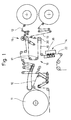
- Fig. 1 shows a film unit as part of a Packaging machine.
- a film web 10 is continuously pulled off a bobbin 11 and guided over a variety of deflection and control rollers.
- a tear strip 12, 13 is in continuous Transport of the film web 10 applied to this and in the area a sealing station 14 also during continuous transport connected to the film web 10 by the application of heat and pressure.
- the unit consisting of film web 10 and tear strip 12, 13 is fed to the packaging machine or a separating unit for cutting off blanks for the outer wrapping.
- a special feature of the device shown in Fig. 1 exists in that it is designed for two-lane operation.
- the film web 10 drawn off from the bobbin 11 has double Width.
- the film web 10 in two side-by-side film webs half width split a middle longitudinal section.
- the two running side by side Foil webs 10 are in the area of a spreading station 16 deflected by spreading rollers 17 so that the two Foil webs 10 are transported parallel at a distance from each other become.
- Each of the film webs 10 is assigned a tear strip 12, 13. These are deducted from separate bobbins. In the area of a union roller 20, the deflecting roller at the same time is 10 for the two film webs, the tear strips 12 and 13 to the assigned, running side by side Foil sheets 10 created.
- Both film webs 10 with tear strips that fit the pack 12, 13 are then the sealing station 14 running side by side fed. There is each film web 10 with tear strips 12, 13 assigned a sealing unit 21. Each of the co-rotating, continuously conveyed film webs 10 is by a sealing unit 21 with the tear strip attached 12, 13 connected. Following the sealing station 14 are therefore two film webs 10 each with a sealed Tear strips 12, 13 transported in parallel and the other Processing fed.
- the tear strips 12, 13 are designed or with a Coating provided that a durable connection with the film web 10 guaranteed when applying heat and pressure.
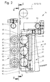
- the sealing unit 21 is designed so that heat and pressure during the continuous transport of the film webs 10 continuously applied to this or to the tear strips 12, 13 become.
- the sealing unit 21 is in the present embodiment in the area of an upright strand 22 of the film webs 10 and tear strips 12, 13 effective.
- the film web act several in the longitudinal direction of the film web 10 successive sealing rolls 23, 24, 25 on film web 10 and tear strips 12, 13 a.
- three sealing rollers 23, 24, 25 on a common, upright Carrier 26 positioned one above the other.
- the sealing rolls 23, 24, 25 are below in the area of the tear strips 12, 13 Transfer of pressure to the tear strips 12, 13 and thus indirectly on the film webs 10.
- Film web 10 are positioned counter pressure elements, namely (Three) counter rollers 27, 28, 29. Also the counter rollers 27..29 are mounted on a common holder 30. The counter rolls 27..29 are positioned exactly opposite the sealing rollers 23..25. Through this film web 10 and tear strips 12, 13th during the conveying movement to the circumference of the counter rollers 27..29 pressed. Sealing rolls 23..25 and counter rolls 27..29 are driven according to the conveying speed of the film web 10, are rotated by this as a result of the conveying movement.
- the sealing rollers 23..25 are heated, so that the Heat is transferred through the sealing rollers 23..25.
- the present exemplary embodiment is indirect heating the sealing rolls 23.25 provided, in particular via Radiant heat.
- the carrier 26 is designed as a housing 31 which holds the sealing rollers 23..25 almost completely surrounds, namely up to small areas or openings 32 for the passage of sealing surfaces the sealing rolls 23..25 in the area of the film web 10.
- the housing 31 is heated directly, in the present case Fall through a longitudinally extending heating cartridge 33. This is positioned in a bore 34 which is on the side opposite the film web 10 in the housing 31 directly next to the peripheral surfaces of the sealing rolls 23..25 extends.
- the housing 31 thus heated transmits the Heat on the sealing rolls 23..25.
- the heating element is at the upper end 33 with a connection 35 for electrical lines Mistake.
- the housing 31 for the sealing rollers 23.25 is special Formed such that (radiant) heat from the housing 31 directly onto the film web 10 or the tear strips 12, 13 is transmitted.
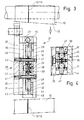
- the housing 31 is in the present Case from two parallel longitudinal walls 36, 37 in which the sealing rollers 23..25 with bolts Axes of rotation 38 are mounted.
- a slewing ring 39 of the sealing rollers 23..25 with a Rolling bearing 40 is rotatably supported on the axis of rotation 38.
- the two longitudinal walls 36, 37 are by transverse connecting bolts 41 connected together. These extend in the area of transverse walls 42 of the housing 31. At the ends, that is above and below, the housing 31 is closed by end walls 43.
- the sealing rolls 23..25 are therefore in each case in chambers 44 stored, only to the side, i.e. towards the film web 10, are open (openings 32).
- the housing 31 designed in this way is on the outside of insulating plates 45 surrounded, reduce the heat loss to the outside.
- the insulation panels 45 extend in the region of the longitudinal walls 36, 37 and of the end walls 43.
- the connecting bolts 41 extend through the insulating plates 45 through, so that the unit from the housing 31 and insulating plates 45 held together by the connecting bolts 41 becomes. These also serve to connect the described Unit with the one-arm lever Carrier 26. Accordingly, the housing 31 is attached laterally.
- additional organs for transferring (radiation) heat to the tear strips 12, 13 are arranged.
- the webs 46 are designed so that they are at a distance from the contour of the sealing rollers 23..25 follow and extend a small distance of, for example 1/5 to 1 ⁇ 2 mm distance from the tear strip 12,. 13 This means that additional heat is transferred without contact.
- the sealing rollers 23..25 are designed in a special way. In the area of the outer sealing surface there is an all-round one Siegelsteg 47 formed. This corresponds approximately to the width of the Tear strips 12, 13 or is slightly wider. By this sealing bar 47 receives the slewing ring 39 as an outer area the sealing rollers 23..25 have a T-shaped cross section. This part of the sealing rollers 23..25 consists of a metallic one Material with high thermal conductivity.
- the counter rollers 27..29 only have the task in the present case to generate the required back pressure when sealing.
- the counter rollers 27..29 are also on roller bearings 48 Axle journal 49 mounted. These are laterally with the one-armed Lever trained holder 30 attached.
- the counter rolls 27..29 have one in relation to the sealing rolls 23..25 wider outer contact or outer surface. at the exemplary embodiment shown is the outer circumference of the counter rollers 27..29 elastic. 5, is for this purpose on the counter rollers 27..29 Jacket 50 made of elastic material attached, in particular Silicone.
- the film web 10 is accordingly by the sealing rolls 23, 24 pressed against the elastic jacket 50. This one has as shown, a spherical outer contact surface 51 here.
- the sealing rolls 23..25 and / or the counter rolls 27..29 are adjustable.
- the carrier is 26 on the one hand and the holder 30 on the other hand movably arranged.
- the angularly shaped support 26 is on a fixed Support pin 52 rotatably mounted.
- the holder 30 for the counter rollers 27..29 is on one side a holding pin 53 rotatably mounted. Through this storage can the relative position of the holder 30 with the counter rollers 27..29 can be set.
Landscapes
- Engineering & Computer Science (AREA)
- Mechanical Engineering (AREA)
- Physics & Mathematics (AREA)
- Thermal Sciences (AREA)
- Auxiliary Devices For And Details Of Packaging Control (AREA)
- Containers And Plastic Fillers For Packaging (AREA)
- Package Closures (AREA)
Claims (11)
- Appareil pour la jonction d'une bandelette de matériau (12, 13) amenée de façon continue, en particulier d'une bandelette de déchirage, à une bande de matériau (10) transportée de façon continue, en particulier une bande de feuille, pour la production de découpes pour des enveloppes de paquets à bandelette de déchirage, la bandelette de matériau (12, 13) pouvant être pressée sur la bande de matériau (10) et jointe à celle-ci par des organes de pression et de soudage chauffés et tournant suivant le mouvement de transport de la bande de matériau (10) et de la bandelette de matériau, comme organe de pression et de soudage étant prévu un rouleau de soudage chauffé, caractérisé par le fait que plusieurs rouleaux de soudage (23, 24, 25) sont placés à la suite les uns des autres dans la direction de transport et sont chauffés principalement ou exclusivement indirectement, que dans la zone entre les rouleaux de soudage successifs (23, 24, 25) et à faible distance de la bande de matériau (10) ou de la bandelette de matériau (12, 13) sont placés des organes de transmission de chaleur, à savoir des entretoises chauffées (46), que ces entretoises (46) sont à paroi mince et s'étendent dans la direction longitudinale de la bandelette de matériau (12, 13), et que les entretoises (46) suivent à distance le contour des rouleaux de soudage (23, 24, 25) placés à la suite les uns des autres dans la direction de transport.
- Appareil selon la revendication 1, caractérisé par le fait que les entretoises (46) sont en matière conductrice de la chaleur.
- Appareil selon l'une des revendications 1 et 2, caractérisé par le fait que les rouleaux de soudage (23, 24, 25) sont montés dans une boíte (31) faite d'une matière à haute conductivité thermique, la boíte étant chauffée, de préférence par au moins une cartouche chauffante (33) placée dans la boíte (31).
- Appareil selon la revendication 1 ou une des autres revendications, caractérisé par le fait que les entretoises (46) sont placées sur une boíte (31) et chauffées par celle-ci ou par une cartouche chauffante (33) placée dans la boíte (31).
- Appareil selon la revendication 1 ou une des autres revendications, caractérisé par le fait que dans la direction de transport de la bande de matériau (10) et de la bandelette de matériau (12, 13) sont placées plusieurs paires de rouleaux de soudage (23, 24, 25) et contre-rouleaux (27, 28, 29) se faisant face, en particulier trois paires de rouleaux de soudage (23, 24, 25) et contre-rouleaux (27, 28, 29) de préférence approximativement de même grandeur.
- Appareil selon la revendication 1 ou une des autres revendications, caractérisé par le fait que les rouleaux de soudage (23, 24, 25) présentent un profil (en forme de T) avec une nervure de soudage extérieure étroite faisant tout le tour (47) pour l'appui sur la bandelette de matériau (12, 13), la nervure de soudage (47) faisant en particulier partie d'une couronne tournante extérieure (39) des rouleaux de soudage (23, 24, 25) et étant en matière conductrice de la chaleur.
- Appareil selon la revendication 1 ou une des autres revendications, caractérisé par le fait que les contre-rouleaux (27, 28, 29) sont constitués en totalité ou en partie, à savoir au moins dans la zone d'une enveloppe extérieure (50), d'un matériau compressible élastiquement, de préférence de silicone.
- Appareil selon la revendication 7 ou une des autres revendications, caractérisé par le fait que les contre-rouleaux (27, 28, 29) présentent une surface d'appui extérieure pour la bande de matériau (10) qui a une plus grande largeur que les surfaces de soudage des rouleaux de soudage (23, 24, 25), en particulier que la nervure de soudage (47).
- Appareil selon la revendication 1 ou une des autres revendications, caractérisé par le fait que les rouleaux de soudage (23, 24, 25) ou la boíte (31) sont placés sur un support (26) qui est monté mobile, en particulier comme levier basculant à un bras.
- Appareil selon la revendication 1 ou une des autres revendications, caractérisé par le fait que les contre-rouleaux (27, 28, 29) sont montés sur un support (30) qui est mobile par rapport aux rouleaux de soudage (23, 24, 25).
- Appareil selon la revendication 1 ou une des autres revendications, caractérisé par le fait que les rouleaux de soudage (23, 24, 25) et les contre-rouleaux (27, 28, 29) agissent dans la zone d'un tronçon de transport vertical, à savoir d'un brin vertical (22) de la bande de matériau (10).
Applications Claiming Priority (2)
| Application Number | Priority Date | Filing Date | Title |
|---|---|---|---|
| DE19619558 | 1996-05-14 | ||
| DE19619558A DE19619558A1 (de) | 1996-05-14 | 1996-05-14 | Vorrichtung zum Verbinden eines Aufreißstreifens mit einer Folienbahn |
Publications (2)
| Publication Number | Publication Date |
|---|---|
| EP0807513A1 EP0807513A1 (fr) | 1997-11-19 |
| EP0807513B1 true EP0807513B1 (fr) | 2002-07-24 |
Family
ID=7794370
Family Applications (1)
| Application Number | Title | Priority Date | Filing Date |
|---|---|---|---|
| EP97107430A Expired - Lifetime EP0807513B1 (fr) | 1996-05-14 | 1997-05-06 | Appareil pour la fixation d'une bande de déchirage sur un film |
Country Status (5)
| Country | Link |
|---|---|
| US (1) | US5858167A (fr) |
| EP (1) | EP0807513B1 (fr) |
| JP (1) | JP3790012B2 (fr) |
| CN (1) | CN1105064C (fr) |
| DE (2) | DE19619558A1 (fr) |
Families Citing this family (7)
| Publication number | Priority date | Publication date | Assignee | Title |
|---|---|---|---|---|
| DE19702473A1 (de) * | 1997-01-24 | 1998-07-30 | Kraemer & Grebe Kg | Verfahren und Vorrichtung zum Siegeln von Folienbahnen |
| DE10034910C2 (de) * | 2000-07-18 | 2002-08-14 | Windmoeller & Hoelscher | Vorrichtung zum Heißsiegeln |
| EP1209083B1 (fr) | 2000-11-24 | 2004-08-18 | Focke & Co. (GmbH & Co.) | Procédé et dispositif pour la production des emballages enveloppes et bobine |
| US6889483B2 (en) * | 2002-10-31 | 2005-05-10 | Cryovac, Inc. | Easy-opening feature for flexible packages and process and apparatus for forming same |
| US7591294B2 (en) * | 2007-11-29 | 2009-09-22 | Spirit Aerosystems, Inc. | Material placement method and apparatus |
| CN105000229B (zh) * | 2015-07-08 | 2017-07-04 | 北京洋航科贸有限公司 | 用于将易撕条封焊于包装体上的装置 |
| IT202300013311A1 (it) * | 2023-06-27 | 2024-12-27 | Pfm S P A | Dispositivo di saldatura per macchina confezionatrice e metodo di saldatura |
Family Cites Families (28)
| Publication number | Priority date | Publication date | Assignee | Title |
|---|---|---|---|---|
| DE7340444U (de) * | 1975-07-31 | Windmoeller & Hoelscher | Vorrichtung zum Aufschweißen von Verstärkungszetteln auf eine Kunststoffolienbahn | |
| DE819497C (de) * | 1941-12-23 | 1951-10-31 | Fischer & Krecke G M B H | Vorrichtung zum Heissverkleben der Laengsnaehte von Zellglasfolien- oder Kunststoff-Folien-Werkstuecken |
| US2451728A (en) * | 1945-04-17 | 1948-10-19 | Breslee Mfg Company | Heat-sealing apparatus |
| US2660219A (en) * | 1950-03-15 | 1953-11-24 | Interstate Folding Box Co | Heat-sealing machine |
| US2845213A (en) * | 1953-06-10 | 1958-07-29 | Bernard J Tamarin | Package with tear tab opening means |
| DE1157765B (de) * | 1959-09-24 | 1963-11-21 | Darex A G | Siegelrolle mit elektrischen Heizdraehten zum Versiegeln von thermoplastischen Kunststoff-Folien |
| US3218961A (en) * | 1961-02-10 | 1965-11-23 | Phillips Petroleum Co | Thermoplastic bag sealer |
| US3059690A (en) * | 1961-07-05 | 1962-10-23 | Ralph A Nyborg | Heat sealing apparatus |
| GB961805A (en) * | 1963-01-26 | 1964-06-24 | Holstein & Kappert Maschf | An apparatus for heat sealing papers or the like coated with plastics material |
| AT245492B (de) * | 1963-08-17 | 1966-02-25 | Hamac Hansella Ag | Vorrichtung zum Anbringen der Längsschweißnaht oder -nähte an der oder den Hüllstoffbahnen in Schlauchbeutelverpackungsmaschinen |
| DE1511626A1 (de) * | 1965-07-19 | 1969-09-11 | Hauni Werke Koerber & Co Kg | Vorrichtung in Packmaschinen zum Verbinden von Teilen des Einschlages von Zigarettenpackungen oder anderen blockfoermigen Gegenstaenden |
| US3484325A (en) * | 1966-07-13 | 1969-12-16 | John M Pendleton | Apparatus for sealing thermoplastic films |
| US3804697A (en) * | 1969-11-24 | 1974-04-16 | Schjeldahl Co G T | Moveable heat sealing apparatus |
| DE2237877C3 (de) * | 1972-08-02 | 1979-01-11 | Packautomatic Gmbh & Co Kg, 5828 Ennepetal | Vorrichtung zum Verschweißen der seitlich überragenden Enden einer ein Packstück enthaltenden schlauchf örmigen Folienhülle |
| US4270965A (en) * | 1976-10-06 | 1981-06-02 | Torterotot Roland | Production of sterile packages |
| US4067761A (en) * | 1976-12-20 | 1978-01-10 | The Kartridg Pak Co. | Plastic web sealing apparatus using hot air heated sealing roller |
| JPS55123411U (fr) * | 1979-02-23 | 1980-09-02 | ||
| US4288967A (en) * | 1979-11-30 | 1981-09-15 | Fuji Machinery Co. Ltd. | Center sealing device for a plastic film in a packaging apparatus |
| DE3542256A1 (de) * | 1985-11-29 | 1987-06-04 | Hoechst Ag | Vorrichtung zum kontinuierlichen schweissen bzw. siegeln von naehten von kunststoff-folien |
| US4666550A (en) * | 1986-02-24 | 1987-05-19 | Philip Morris Incorporated | Apparatus for producing a strip of laminated sheet material |
| US4721501A (en) * | 1986-09-08 | 1988-01-26 | Mobil Oil Corporation | Apparatus for producing a machine-direction heat seal |
| US4717372A (en) * | 1986-12-08 | 1988-01-05 | Mobil Oil Corporation | Apparatus for producing a machine-direction intermittent heat seal |
| IT1207736B (it) * | 1987-06-25 | 1989-05-25 | Gd Spa | Dispositivo per l'applicazione di un nastrino a strappo su un nastro continuo di materiale d'incarto |
| US4808150A (en) * | 1987-09-25 | 1989-02-28 | Mobil Oil Corporation | Oven-heated hot wheel sealing apparatus |
| JPH02258509A (ja) * | 1989-03-28 | 1990-10-19 | Chuo Housouki Kk | 充填包装機に於る包装袋閉じ合せ縁の余剰部切落装置 |
| DE9012482U1 (de) * | 1990-08-31 | 1990-11-08 | Rovema - Verpackungsmaschinen GmbH, 6301 Fernwald | Längssiegelvorrichtung, insbesondere für eine Schlauchbeutelmaschine |
| DE4215690A1 (de) * | 1992-05-14 | 1993-11-18 | Focke & Co | Vorrichtung zum Verbinden eines Aufreißstreifens mit einer Materialbahn |
| JPH0891330A (ja) * | 1994-09-21 | 1996-04-09 | Shikoku Kakoki Co Ltd | シールテープの張付け装置 |
-
1996
- 1996-05-14 DE DE19619558A patent/DE19619558A1/de not_active Withdrawn
-
1997
- 1997-05-06 EP EP97107430A patent/EP0807513B1/fr not_active Expired - Lifetime
- 1997-05-06 DE DE59707766T patent/DE59707766D1/de not_active Expired - Lifetime
- 1997-05-13 US US08/855,541 patent/US5858167A/en not_active Expired - Fee Related
- 1997-05-14 JP JP12441497A patent/JP3790012B2/ja not_active Expired - Fee Related
- 1997-05-14 CN CN97111549A patent/CN1105064C/zh not_active Expired - Fee Related
Also Published As
| Publication number | Publication date |
|---|---|
| EP0807513A1 (fr) | 1997-11-19 |
| JPH1086916A (ja) | 1998-04-07 |
| CN1105064C (zh) | 2003-04-09 |
| US5858167A (en) | 1999-01-12 |
| CN1169388A (zh) | 1998-01-07 |
| DE19619558A1 (de) | 1997-11-20 |
| DE59707766D1 (de) | 2002-08-29 |
| JP3790012B2 (ja) | 2006-06-28 |
Similar Documents
| Publication | Publication Date | Title |
|---|---|---|
| DE3142202C2 (fr) | ||
| DE3416721C2 (de) | Vorrichtung zum Wickeln einer Bahn | |
| DE3502608C2 (fr) | ||
| DE69018164T2 (de) | Maschine und Verfahren zum Anbringen zusätzlicher Umhüllungen an zylindrischen Gegenständen. | |
| DE3039293A1 (de) | Vorrichtung zum zufuehren eines einwickelbogens zu einer grossen papierrolle o.dgl. | |
| EP1751005B1 (fr) | Procede et dispositif d'emballage d'objets plats | |
| DE4215690A1 (de) | Vorrichtung zum Verbinden eines Aufreißstreifens mit einer Materialbahn | |
| EP1044882A1 (fr) | Dispositif pour emballer un rouleau d'une bande de matériau | |
| EP0807513B1 (fr) | Appareil pour la fixation d'une bande de déchirage sur un film | |
| DE1586093A1 (de) | Einrichtung zum Aufbringen von Aufreissstreifen auf ein Einschlagmaterialband | |
| DE4340039C2 (de) | Beschichtungseinrichtung für laufende Bahnen aus Papier oder Karton | |
| EP0812257B1 (fr) | Procede et dispositif de chauffage d'une bande en mouvement, notamment d'une bande de carton ondule | |
| DE3002092C2 (de) | Vorrichtung zum Zuführen von bandförmigem Verpackungsmaterial | |
| DE2914696C2 (de) | Vorrichtung zum Aufbringen von mit einem Kleber versehenen Reiterbändern auf die flachliegenden Stirnkanten von Schlauchabschnitten oder Säcken | |
| DE914598C (de) | Verfahren und Vorrichtung zum Etikettieren von runden Gegenstaenden, wie Glasroehrchen, Papproehrchen od. dgl. | |
| EP0014858B1 (fr) | Procédé et dispositif pour appliquer des rubans d'ouverture ou analogues sur une feuille de matériau d'empaquetage | |
| DE3821266A1 (de) | Vorrichtung fuer die anbringung eines aufreissstreifens | |
| DE19983258B4 (de) | Vorrichtung und Verfahren zum Kaschieren von Papier | |
| EP0972707A1 (fr) | Procédé et dispositif pour emballer un rouleau de matériau en bande | |
| DE19546697A1 (de) | Fördereinrichtung für zu beleimende Zuschnitte aus Verpackungsmaterial zu einer Zigarettenverpackungsmaschine | |
| EP0719228A1 (fr) | Methode et dispositif pour l'emballage de profiles | |
| EP0406988B1 (fr) | Rouleaux de gaufrage | |
| DE2166300C3 (de) | Ein wickelmaschine | |
| DE1586093C3 (de) | Vorrichtung zum Aufbringen von Aufreißstreifen auf ein Einschlagmaterialband | |
| DE2013063C (de) | Verfahren zum Oberflachenverguten von Holzwerkstoffplatten |
Legal Events
| Date | Code | Title | Description |
|---|---|---|---|
| PUAI | Public reference made under article 153(3) epc to a published international application that has entered the european phase |
Free format text: ORIGINAL CODE: 0009012 |
|
| AK | Designated contracting states |
Kind code of ref document: A1 Designated state(s): CH DE GB IT LI |
|
| 17P | Request for examination filed |
Effective date: 19971227 |
|
| 17Q | First examination report despatched |
Effective date: 19990526 |
|
| GRAG | Despatch of communication of intention to grant |
Free format text: ORIGINAL CODE: EPIDOS AGRA |
|
| GRAG | Despatch of communication of intention to grant |
Free format text: ORIGINAL CODE: EPIDOS AGRA |
|
| GRAH | Despatch of communication of intention to grant a patent |
Free format text: ORIGINAL CODE: EPIDOS IGRA |
|
| GRAH | Despatch of communication of intention to grant a patent |
Free format text: ORIGINAL CODE: EPIDOS IGRA |
|
| GRAA | (expected) grant |
Free format text: ORIGINAL CODE: 0009210 |
|
| AK | Designated contracting states |
Kind code of ref document: B1 Designated state(s): CH DE GB IT LI |
|
| REG | Reference to a national code |
Ref country code: GB Ref legal event code: FG4D Free format text: NOT ENGLISH |
|
| REG | Reference to a national code |
Ref country code: CH Ref legal event code: EP |
|
| GBT | Gb: translation of ep patent filed (gb section 77(6)(a)/1977) |
Effective date: 20020724 |
|
| REG | Reference to a national code |
Ref country code: CH Ref legal event code: NV Representative=s name: DIPL.-ING. ETH H. R. WERFFELI PATENTANWALT |
|
| REF | Corresponds to: |
Ref document number: 59707766 Country of ref document: DE Date of ref document: 20020829 |
|
| PLBE | No opposition filed within time limit |
Free format text: ORIGINAL CODE: 0009261 |
|
| STAA | Information on the status of an ep patent application or granted ep patent |
Free format text: STATUS: NO OPPOSITION FILED WITHIN TIME LIMIT |
|
| 26N | No opposition filed |
Effective date: 20030425 |
|
| PGFP | Annual fee paid to national office [announced via postgrant information from national office to epo] |
Ref country code: CH Payment date: 20060515 Year of fee payment: 10 |
|
| REG | Reference to a national code |
Ref country code: CH Ref legal event code: PL |
|
| PG25 | Lapsed in a contracting state [announced via postgrant information from national office to epo] |
Ref country code: CH Free format text: LAPSE BECAUSE OF NON-PAYMENT OF DUE FEES Effective date: 20070531 Ref country code: LI Free format text: LAPSE BECAUSE OF NON-PAYMENT OF DUE FEES Effective date: 20070531 |
|
| PGFP | Annual fee paid to national office [announced via postgrant information from national office to epo] |
Ref country code: IT Payment date: 20090516 Year of fee payment: 13 |
|
| PGFP | Annual fee paid to national office [announced via postgrant information from national office to epo] |
Ref country code: GB Payment date: 20090506 Year of fee payment: 13 |
|
| GBPC | Gb: european patent ceased through non-payment of renewal fee |
Effective date: 20100506 |
|
| PG25 | Lapsed in a contracting state [announced via postgrant information from national office to epo] |
Ref country code: IT Free format text: LAPSE BECAUSE OF NON-PAYMENT OF DUE FEES Effective date: 20100506 |
|
| PG25 | Lapsed in a contracting state [announced via postgrant information from national office to epo] |
Ref country code: GB Free format text: LAPSE BECAUSE OF NON-PAYMENT OF DUE FEES Effective date: 20100506 |
|
| PGFP | Annual fee paid to national office [announced via postgrant information from national office to epo] |
Ref country code: DE Payment date: 20130527 Year of fee payment: 17 |
|
| REG | Reference to a national code |
Ref country code: DE Ref legal event code: R119 Ref document number: 59707766 Country of ref document: DE |
|
| REG | Reference to a national code |
Ref country code: DE Ref legal event code: R119 Ref document number: 59707766 Country of ref document: DE Effective date: 20141202 |
|
| PG25 | Lapsed in a contracting state [announced via postgrant information from national office to epo] |
Ref country code: DE Free format text: LAPSE BECAUSE OF NON-PAYMENT OF DUE FEES Effective date: 20141202 |