EP0807521A1 - Procédée et dispositif d'accrochage d'un blanchet pour une machine rotative - Google Patents
Procédée et dispositif d'accrochage d'un blanchet pour une machine rotative Download PDFInfo
- Publication number
- EP0807521A1 EP0807521A1 EP97401085A EP97401085A EP0807521A1 EP 0807521 A1 EP0807521 A1 EP 0807521A1 EP 97401085 A EP97401085 A EP 97401085A EP 97401085 A EP97401085 A EP 97401085A EP 0807521 A1 EP0807521 A1 EP 0807521A1
- Authority
- EP
- European Patent Office
- Prior art keywords
- blanket
- cylinder
- leading edge
- gap
- flat bar
- Prior art date
- Legal status (The legal status is an assumption and is not a legal conclusion. Google has not performed a legal analysis and makes no representation as to the accuracy of the status listed.)
- Granted
Links
- 238000000034 method Methods 0.000 title claims description 15
- 238000007639 printing Methods 0.000 abstract description 34
- 230000003247 decreasing effect Effects 0.000 abstract description 12
- 239000000945 filler Substances 0.000 description 7
- 230000000694 effects Effects 0.000 description 4
- 230000013011 mating Effects 0.000 description 4
- 239000000463 material Substances 0.000 description 2
- 238000007645 offset printing Methods 0.000 description 2
- 229910000831 Steel Inorganic materials 0.000 description 1
- XAGFODPZIPBFFR-UHFFFAOYSA-N aluminium Chemical compound [Al] XAGFODPZIPBFFR-UHFFFAOYSA-N 0.000 description 1
- 229910052782 aluminium Inorganic materials 0.000 description 1
- 238000003780 insertion Methods 0.000 description 1
- 230000037431 insertion Effects 0.000 description 1
- 238000012856 packing Methods 0.000 description 1
- 239000010959 steel Substances 0.000 description 1
Images

Classifications
-
- B—PERFORMING OPERATIONS; TRANSPORTING
- B41—PRINTING; LINING MACHINES; TYPEWRITERS; STAMPS
- B41F—PRINTING MACHINES OR PRESSES
- B41F13/00—Common details of rotary presses or machines
- B41F13/08—Cylinders
- B41F13/193—Transfer cylinders; Offset cylinders
-
- B—PERFORMING OPERATIONS; TRANSPORTING
- B41—PRINTING; LINING MACHINES; TYPEWRITERS; STAMPS
- B41F—PRINTING MACHINES OR PRESSES
- B41F30/00—Devices for attaching coverings or make-ready devices; Guiding devices for coverings
- B41F30/04—Devices for attaching coverings or make-ready devices; Guiding devices for coverings attaching to transfer cylinders
Definitions
- the present invention relates to a method and an apparatus for mounting a blanket for a rotary press and, more particularly, a method and an apparatus for mounting a blanket, which can reduce the vibration caused by a cylinder gap on a blanket cylinder and the length of an unprinted portion (hereinafter referred to as a non printing length).
- a blanket cylinder of a printing machine comes in contact with a plate cylinder, a blanket cylinder or an impression cylinder, and rotates on the mating cylinder while cooperating with each other.
- FIG. 6 shows a most basic cylinder arrangement for a printing unit on an offset printing machine.
- paper is made to pass between an outer blanket cylinder 61 and an inner blanket cylinder 62 to make printing on both faces of the paper at the same time.
- reference numerals 64 and 65 denote an outer plate cylinder and an inner plate cylinder, respectively.
- a blanket-mounting cylinder gap 3 for stretching a blanket 2 around the blanket cylinder is formed in parallel with the cylinder axis.
- the lower part of this cylinder gap 3 communicates with a through hole 67 for providing a blanket reel bar 54.
- FIG. 7 shows a blanket mounting apparatus 50 which has so far been used generally.
- a blanket having aluminum pieces 59, 59 pressed onto both ends thereof is used.
- the pieces 59, 59 at both ends of the blanket are inserted in a gap in two reel bars 54, 54 provided in the blanket cylinders respectively, and the blanket 2 is stretched around the blanket cylinder 1 by the double reel method by turning the reel bars 54, 54.
- the cylinder gap 3 on the blanket cylinder 61 (62) of the printing machine meets the cylinder gap 3 of the rotating mating blanket cylinder 61 (62) every one rotation, and also meets a plate mounting gap 66 on the plate cylinder 64 (65). Therefore, when these cylinder gaps 3, 3 meet each other during rotation, a printing pressure is released in a moment, which creates a large disturbing force acting on the printing machine, resulting in a printing trouble such as a lateral stripe called shock-streak on the print surface.
- FIG. 8 shows a publicly known double reel type blanket mounting apparatus 4 which has been developed to prevent the shock-streaks.
- an elastic filler 48 is installed at the opening between a leading edge 2a and a tail edge 2b of the blanket 2 at the cylinder gap 3.
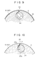
- FIG. 9 shows a publicly known blanket mounting apparatus which has recently been developed to prevent the shock-streaks and to shorten the non printing length.
- a blanket 2 is affixed to the surface of a base plate 32 using a form plate material, and a mechanism 34 of a plate lock up device for plate cylinder, which can decrease the cylinder gap width, is applied.
- FIG. 10 shows a single reel type blanket mounting apparatus 20 which has recently been developed and widely used now to prevent the shock-streaks and to shorten the non printing length.
- a blanket 2 having thin flat bars 25a, 25b affixed on one side at both ends thereof is used so as to decrease the width of a cylinder gap 3 on a blanket cylinder 1 to the limit point such that there is no difficulty in mounting the blanket 2.
- an object of the present invention is to solve the above remaining problems and to provide an economical and highly operable blanket mounting method and apparatus in which the width of a cylinder gap on a blanket cylinder is further decreased to eliminate a printing trouble such as shock-streak and to shorten the non printing length.
- the present invention provides a blanket mounting method characterized in that on a blanket mounting apparatus of a type such that the tail edge of a blanket having a flat bar fixed at each end is reeled by a blanket reel bar provided at the lower part of a cylinder gap on a blanket cylinder, a notch with the same size as that of the leading edge flat bar of the blanket is provided along the leading edge opening of the cylinder gap, and the leading edge flat bar of the blanket is inserted in the notch to mount the blanket around the cylinder.
- the present invention provides, as an apparatus for using the above method, a blanket mounting apparatus characterized in that on a blanket mounting apparatus of a type such that the tail edge of a blanket having a flat bar fixed at each end is reeled by a blanket reel bar provided at the lower part of a cylinder gap on a blanket cylinder, a notch with the same size as that of the leading edge flat bar of the blanket is formed along the leading edge opening of the cylinder gap so that the leading edge flat bar of the blanket is inserted therein.
- the tail edge of the blanket is first inserted in the gap of the reel bar in the blanket cylinder. Then, the leading edge is inserted in the notch formed at the opening of the cylinder gap on the blanket cylinder.
- the leading edge is pushed into the notch until the tip end of the leading edge flat bar of the blanket comes in contact with the lower face of the notch.
- the blanket reel bar is turned to stretch the blanket around the blanket cylinder.
- the notch formed at the opening of the cylinder gap on the blanket cylinder is blocked by the leading edge flat bar of the blanket, so that the width of the gap on the blanket cylinder is decreased by the thickness of the flat bar as if a filler with a thickness of flat bar is inserted.
- the gap width of the blanket cylinder excluding the width of the notch at the opening of the cylinder gap is formed into a dimension equivalent to the maximum thickness of two blankets, the leading edge and the tail edge of the blanket come in contact with each other at the entrance of the gap on the blanket cylinder, so that the non printing length caused by the gap width of the blanket cylinder can be decreased to a dimension equivalent to the maximum thickness of two blankets.
- the disturbing force during operation and the non printing length can be reduced significantly by the decrease in gap width.
- FIGS. 1 to 3 are sectional views of the principal portion of a blanket mounting apparatus in accordance with one embodiment of the present invention.
- FIG. 1 shows a state of a blanket cylinder before a blanket is mounted
- FIG. 2 shows a state when the blanket is being mounted
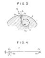
- FIG. 3 shows a state when the blanket has been mounted.
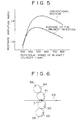
- FIG. 4 is a side view of a blanket used in this embodiment
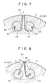
- FIG. 5 is a graph showing an effect achieved by this embodiment.
- reference numeral 10 denotes a blanket mounting apparatus in accordance with this embodiment
- 1 denotes a blanket cylinder thereof
- 2 denotes a blanket stretched around the blanket cylinder
- 3 denotes a blanket mounting cylinder gap formed in parallel with the axis of the blanket cylinder
- 14 denotes a blanket reel bar provided at the bottom part of the cylinder gap 3.
- steel flat bars 15a on the leading edge side and 15b on the tail edge side are affixed to the leading edge 2a and the tail edge 2b at both ends, respectively.
- a notch 16 whose depth and width are equal to the width w and thickness t of the flat bar on the leading edge side of the blanket, respectively, is formed on the surface parallel with the radius r passing the center of the cylinder gap 3 along a leading edge opening 3a of the cylinder gap 3.
- the cylinder gap 3 is so formed that the apparent width B thereof on the blanket cylinder 1 including the width of the notch 16 at the leading edge opening 3a is equal to the maximum thickness of two blankets plus the thickness t of the flat bar 15a on the leading edge side.
- a gap 17 is formed to insert the tail edge 2b of the blanket, and this reel bar is configured so as to be turned via a worm gear mechanism, not shown.
- the tail edge 2b of the blanket 2 is first inserted in the gap 17 of the blanket reel bar 14. Then, the leading edge 2a of the blanket 2 is inserted in the notch 16 formed at the leading edge opening 3a of the cylinder gap 3 on the blanket cylinder.
- the leading edge 2b is pushed into the notch 16 until the tip end of the leading edge flat bar 15a of the blanket 2 comes in contact with the lower face of the notch 16.
- the blanket reel bar 14 is turned in the arrow-marked direction via a worm gear, not shown, for tightening, so that the blanket 2 is stretched around the blanket cylinder 1.
- the notch 16 formed at the leading edge opening 3a of the cylinder gap 3 on the blanket cylinder 1 is blocked by the leading edge flat bar 15a of the blanket 2, so that as shown in FIG. 3, the leading edge 2a and the tail edge 2b of the blanket 2 come in contact with each other at the portion where the blanket 2 enters the cylinder gap 3.
- the substantial width of gap on the blanket cylinder 1 is decreased by the thickness t of the leading edge flat bar 15a, becoming a dimension equivalent to the maximum thickness of two blankets, so that a state as if a filler with the thickness t of the flat bar 15a is inserted is established.
- the non printing length L produced by the gap width of the blanket cylinder can be decreased to a dimension equivalent to the maximum thickness of two blankets.
- a disturbing force generated when the cylinder. gap 3 on the blanket cylinder 1 meets the cylinder gap 3 of the mating cylinder cooperating with each other can be reduced significantly.
- FIG. 5 shows the relationship between the rotational speed of the blanket cylinder 1 and the response amplitude ratio.
- ⁇ mark indicates the case of the above-described advanced type conventional blanket mounting apparatus 20
- O mark indicates the case of the blanket mounting apparatus 10 of the present invention.
- the response amplitude ratio can be reduced by about 20% over the whole range of normal speed as compared with the conventional apparatus 20. Therefore, as the operating speed increases, the effect of decreased vibration increases.
- the substantial gap width of the blanket cylinder 1 is decreased to shorten the non printing length L, and the vibration during operation is reduced significantly, by which high-quality printed matters without a printing trouble such as shock-streak can be obtained over the whole range of the used rotational speed of rotary press.
- the present invention achieves the following effects because the leading edge flat bar is inserted in the notch formed at the leading edge opening of the cylinder gap on the blanket cylinder.
- the present invention provides a blanket mounting apparatus in which the non printing length is shortened by further decreasing the width of the cylinder gap on the blanket cylinder, and high-grade printing without a printing trouble such as shock-streak can be performed by decreasing the change in printing pressure, and moreover the operability is excellent.
Landscapes
- Engineering & Computer Science (AREA)
- Mechanical Engineering (AREA)
- Supply, Installation And Extraction Of Printed Sheets Or Plates (AREA)
- Printing Plates And Materials Therefor (AREA)
Applications Claiming Priority (3)
| Application Number | Priority Date | Filing Date | Title |
|---|---|---|---|
| JP123236/96 | 1996-05-17 | ||
| JP12323696 | 1996-05-17 | ||
| JP8123236A JPH09300588A (ja) | 1996-05-17 | 1996-05-17 | 輪転機のブランケット装着方法および装着装置 |
Publications (2)
| Publication Number | Publication Date |
|---|---|
| EP0807521A1 true EP0807521A1 (fr) | 1997-11-19 |
| EP0807521B1 EP0807521B1 (fr) | 2000-04-26 |
Family
ID=14855578
Family Applications (1)
| Application Number | Title | Priority Date | Filing Date |
|---|---|---|---|
| EP97401085A Expired - Lifetime EP0807521B1 (fr) | 1996-05-17 | 1997-05-15 | Procédé d'accrochage d'un blanchet pour une machine rotative |
Country Status (4)
| Country | Link |
|---|---|
| US (1) | US5787812A (fr) |
| EP (1) | EP0807521B1 (fr) |
| JP (1) | JPH09300588A (fr) |
| DE (1) | DE69701764T2 (fr) |
Cited By (1)
| Publication number | Priority date | Publication date | Assignee | Title |
|---|---|---|---|---|
| EP1607219A1 (fr) * | 1999-09-22 | 2005-12-21 | Tokyo Kikai Seisakusho Ltd. | Blanchet pour machine d'impression |
Families Citing this family (4)
| Publication number | Priority date | Publication date | Assignee | Title |
|---|---|---|---|---|
| US7036429B2 (en) * | 1999-10-20 | 2006-05-02 | Man Roland Druckmaschinen Ag | Rubber blanket cylinder sleeve for web fed rotary printing machines |
| EP1334825B1 (fr) * | 1999-12-02 | 2011-06-01 | Koenig & Bauer Aktiengesellschaft | Groupe d'impression d'une machine d'impression |
| US7225737B2 (en) * | 2003-12-09 | 2007-06-05 | Kodak Graphic Communications Canada Company | Method for automated platemaking |
| US9821547B2 (en) * | 2013-12-13 | 2017-11-21 | Day International, Inc. | Printing blanket with non-extensible backing mountable in a single reel rod lock-up |
Citations (8)
| Publication number | Priority date | Publication date | Assignee | Title |
|---|---|---|---|---|
| DE451539C (de) * | 1925-01-26 | 1927-10-28 | Robert John | Drucktuch mit Metallruecken und zusammendrueckbarer Auflage, Befestigung und Druckverfahren unter Verwendung des Drucktuchs |
| GB756867A (en) * | 1953-09-02 | 1956-09-12 | Crabtree & Sons Ltd R | A new or improved means for securing blankets to the impression cylinders of printing machines |
| US2986085A (en) * | 1959-04-13 | 1961-05-30 | Cottrell Company | Printing cylinders for rotary web presses |
| DE2163417A1 (de) * | 1971-12-21 | 1973-07-05 | Maschf Augsburg Nuernberg Ag | Einrichtung zum befestigen des gummituches bzw. einer druckplatte auf dem gummi- oder plattenzylinder einer rotationsoffsetdruckmaschine |
| US4090302A (en) * | 1977-03-17 | 1978-05-23 | Dayco Corporation | Printing blanket holding bar gage |
| EP0132532A1 (fr) * | 1983-07-21 | 1985-02-13 | M.A.N.-ROLAND Druckmaschinen Aktiengesellschaft | Cylindre pour une machine rotative d'impression |
| DE3338450C1 (de) * | 1983-10-22 | 1985-06-05 | M.A.N.- Roland Druckmaschinen AG, 6050 Offenbach | Einrichtung zum Einfuehren der Endabschnitte eines flexiblen Aufzuges in eine Grube eines Zylinders einer Druckmaschine |
| WO1989001866A1 (fr) * | 1987-09-04 | 1989-03-09 | Drg (Uk) Limited | Plaque d'impression |
Family Cites Families (11)
| Publication number | Priority date | Publication date | Assignee | Title |
|---|---|---|---|---|
| US1578736A (en) * | 1925-01-26 | 1926-03-30 | John Robert | Blanket for printing presses, process for forming the same, and process of printing employing same |
| US3166012A (en) * | 1962-08-22 | 1965-01-19 | Hantscho Co George | Coacting cylinders having skewed gaps to maintain balanced pressure contact |
| US3296673A (en) * | 1964-05-04 | 1967-01-10 | Alven D Kirkpatrick | Printing blanket edging and anchoring means |
| US3844214A (en) * | 1971-11-01 | 1974-10-29 | Dayco Corp | Printing blanket bar assembly with edging strip locking means |
| DE3364104D1 (en) * | 1983-01-18 | 1986-07-17 | De La Rue Giori Sa | Flexible sheet attaching device for a printing cylinder of a rotary printing machine |
| US4635550A (en) * | 1985-03-11 | 1987-01-13 | American Roller Company | Gap filler blanket for printing cylinder |
| DE3540581A1 (de) * | 1985-11-15 | 1987-05-21 | Roland Man Druckmasch | Druckwerkzylinder mit einem in dessen zylindergrube angeordneten fuellstueck |
| DE4034767A1 (de) * | 1989-12-01 | 1991-06-06 | Heidelberger Druckmasch Ag | Druckwerkszylinder fuer rotationsdruckmaschinen |
| DE4102858A1 (de) * | 1990-03-08 | 1991-09-12 | Heidelberger Druckmasch Ag | Druckwerkszylinder fuer rotationsdruckmaschinen |
| JPH07285214A (ja) * | 1994-04-18 | 1995-10-31 | Mitsubishi Heavy Ind Ltd | ブランケット装着方法及び装置 |
| JPH08118603A (ja) * | 1994-10-24 | 1996-05-14 | Mitsubishi Heavy Ind Ltd | 印刷胴の緩衝装置 |
-
1996
- 1996-05-17 JP JP8123236A patent/JPH09300588A/ja not_active Withdrawn
-
1997
- 1997-01-07 US US08/779,443 patent/US5787812A/en not_active Expired - Fee Related
- 1997-05-15 EP EP97401085A patent/EP0807521B1/fr not_active Expired - Lifetime
- 1997-05-15 DE DE69701764T patent/DE69701764T2/de not_active Expired - Fee Related
Patent Citations (8)
| Publication number | Priority date | Publication date | Assignee | Title |
|---|---|---|---|---|
| DE451539C (de) * | 1925-01-26 | 1927-10-28 | Robert John | Drucktuch mit Metallruecken und zusammendrueckbarer Auflage, Befestigung und Druckverfahren unter Verwendung des Drucktuchs |
| GB756867A (en) * | 1953-09-02 | 1956-09-12 | Crabtree & Sons Ltd R | A new or improved means for securing blankets to the impression cylinders of printing machines |
| US2986085A (en) * | 1959-04-13 | 1961-05-30 | Cottrell Company | Printing cylinders for rotary web presses |
| DE2163417A1 (de) * | 1971-12-21 | 1973-07-05 | Maschf Augsburg Nuernberg Ag | Einrichtung zum befestigen des gummituches bzw. einer druckplatte auf dem gummi- oder plattenzylinder einer rotationsoffsetdruckmaschine |
| US4090302A (en) * | 1977-03-17 | 1978-05-23 | Dayco Corporation | Printing blanket holding bar gage |
| EP0132532A1 (fr) * | 1983-07-21 | 1985-02-13 | M.A.N.-ROLAND Druckmaschinen Aktiengesellschaft | Cylindre pour une machine rotative d'impression |
| DE3338450C1 (de) * | 1983-10-22 | 1985-06-05 | M.A.N.- Roland Druckmaschinen AG, 6050 Offenbach | Einrichtung zum Einfuehren der Endabschnitte eines flexiblen Aufzuges in eine Grube eines Zylinders einer Druckmaschine |
| WO1989001866A1 (fr) * | 1987-09-04 | 1989-03-09 | Drg (Uk) Limited | Plaque d'impression |
Cited By (1)
| Publication number | Priority date | Publication date | Assignee | Title |
|---|---|---|---|---|
| EP1607219A1 (fr) * | 1999-09-22 | 2005-12-21 | Tokyo Kikai Seisakusho Ltd. | Blanchet pour machine d'impression |
Also Published As
| Publication number | Publication date |
|---|---|
| EP0807521B1 (fr) | 2000-04-26 |
| DE69701764T2 (de) | 2000-11-16 |
| DE69701764D1 (de) | 2000-05-31 |
| US5787812A (en) | 1998-08-04 |
| JPH09300588A (ja) | 1997-11-25 |
Similar Documents
| Publication | Publication Date | Title |
|---|---|---|
| RU2170177C2 (ru) | Прижимной цилиндр листовой печатной машины | |
| US3533355A (en) | Printing plate saddle | |
| US3926118A (en) | Rotary printing press impression cylinder having clamping and sheet gripping devices | |
| US4508033A (en) | Traveling paper web capturing apparatus for use with a rotary printing machine | |
| US7681499B2 (en) | Gap filling member for blanket cylinder | |
| US6439117B1 (en) | Printing press with multi-plate plate cylinder | |
| JPH0430910B2 (fr) | ||
| US3425348A (en) | Clamping arrangement for blanket in printing press | |
| EP0807521B1 (fr) | Procédé d'accrochage d'un blanchet pour une machine rotative | |
| US4688483A (en) | Clamping device for a printing plate of an offset printing machine | |
| US4648318A (en) | Rubber blanket attachment arrangement for an offset rotary printing machine | |
| US3583318A (en) | Printing plate clamping means | |
| US5123353A (en) | Plate lock-up apparatus | |
| JPH0790635B2 (ja) | 輪転印刷機の印刷胴のための2層の胴被覆部材のうちの下層を保持するための装置 | |
| US3453955A (en) | Shock absorber with movement limiting stop for rotary printing press cylinders | |
| US5778786A (en) | Plate clamping device for reducing the non-printing region | |
| US6101941A (en) | Printing unit cylinder of a rotary printing press and bent printing form fastenable on a printing form cylinder of a rotary printing press | |
| GB2167011A (en) | Rubber blanket cylinder for a rotary printing press | |
| JPH02196658A (ja) | 印刷機の版胴とブランケット胴におけるギャップ形状およびブランケット金具 | |
| US5245924A (en) | Locking and adjusting device for a printing press | |
| US3453956A (en) | Shock absorber for rotary printing press cylinders | |
| US20040099164A1 (en) | Magnetic tucker bar for a printing press | |
| US6655283B2 (en) | Method and device for fastening a printing plate to a plate cylinder of a rotary printing machine | |
| GB2137141A (en) | Blanket Cylinder for Web Printing Presses | |
| JP4021856B2 (ja) | 輪転印刷機の印刷胴構造 |
Legal Events
| Date | Code | Title | Description |
|---|---|---|---|
| PUAI | Public reference made under article 153(3) epc to a published international application that has entered the european phase |
Free format text: ORIGINAL CODE: 0009012 |
|
| AK | Designated contracting states |
Kind code of ref document: A1 Designated state(s): DE FR |
|
| 17P | Request for examination filed |
Effective date: 19980323 |
|
| 17Q | First examination report despatched |
Effective date: 19980714 |
|
| GRAG | Despatch of communication of intention to grant |
Free format text: ORIGINAL CODE: EPIDOS AGRA |
|
| RTI1 | Title (correction) |
Free format text: METHOD FOR MOUNTING A BLANKET FOR A ROTARY PRESS |
|
| GRAG | Despatch of communication of intention to grant |
Free format text: ORIGINAL CODE: EPIDOS AGRA |
|
| GRAH | Despatch of communication of intention to grant a patent |
Free format text: ORIGINAL CODE: EPIDOS IGRA |
|
| GRAH | Despatch of communication of intention to grant a patent |
Free format text: ORIGINAL CODE: EPIDOS IGRA |
|
| GRAA | (expected) grant |
Free format text: ORIGINAL CODE: 0009210 |
|
| AK | Designated contracting states |
Kind code of ref document: B1 Designated state(s): DE FR |
|
| PG25 | Lapsed in a contracting state [announced via postgrant information from national office to epo] |
Ref country code: FR Free format text: LAPSE BECAUSE OF FAILURE TO SUBMIT A TRANSLATION OF THE DESCRIPTION OR TO PAY THE FEE WITHIN THE PRESCRIBED TIME-LIMIT Effective date: 20000426 |
|
| REF | Corresponds to: |
Ref document number: 69701764 Country of ref document: DE Date of ref document: 20000531 |
|
| EN | Fr: translation not filed | ||
| PLBE | No opposition filed within time limit |
Free format text: ORIGINAL CODE: 0009261 |
|
| STAA | Information on the status of an ep patent application or granted ep patent |
Free format text: STATUS: NO OPPOSITION FILED WITHIN TIME LIMIT |
|
| 26N | No opposition filed | ||
| PGFP | Annual fee paid to national office [announced via postgrant information from national office to epo] |
Ref country code: DE Payment date: 20010508 Year of fee payment: 5 |
|
| PG25 | Lapsed in a contracting state [announced via postgrant information from national office to epo] |
Ref country code: DE Free format text: LAPSE BECAUSE OF NON-PAYMENT OF DUE FEES Effective date: 20021203 |