EP0807532A1 - Dispositif de tampon - Google Patents
Dispositif de tampon Download PDFInfo
- Publication number
- EP0807532A1 EP0807532A1 EP97303234A EP97303234A EP0807532A1 EP 0807532 A1 EP0807532 A1 EP 0807532A1 EP 97303234 A EP97303234 A EP 97303234A EP 97303234 A EP97303234 A EP 97303234A EP 0807532 A1 EP0807532 A1 EP 0807532A1
- Authority
- EP
- European Patent Office
- Prior art keywords
- seal plate
- supporter
- pinching
- face
- pivoting
- Prior art date
- Legal status (The legal status is an assumption and is not a legal conclusion. Google has not performed a legal analysis and makes no representation as to the accuracy of the status listed.)
- Withdrawn
Links
- 210000000078 claw Anatomy 0.000 claims abstract description 22
- 239000012790 adhesive layer Substances 0.000 claims abstract description 5
- 239000012466 permeate Substances 0.000 claims description 28
- 239000006260 foam Substances 0.000 claims description 15
- 229920003023 plastic Polymers 0.000 claims description 14
- 239000004033 plastic Substances 0.000 claims description 14
- 239000000758 substrate Substances 0.000 claims description 11
- 239000000853 adhesive Substances 0.000 description 4
- 229920005989 resin Polymers 0.000 description 4
- 239000011347 resin Substances 0.000 description 4
- 238000005187 foaming Methods 0.000 description 2
- 238000000034 method Methods 0.000 description 2
- 238000012986 modification Methods 0.000 description 2
- 230000004048 modification Effects 0.000 description 2
- 239000010409 thin film Substances 0.000 description 2
- BZHJMEDXRYGGRV-UHFFFAOYSA-N Vinyl chloride Chemical compound ClC=C BZHJMEDXRYGGRV-UHFFFAOYSA-N 0.000 description 1
- 229920000122 acrylonitrile butadiene styrene Polymers 0.000 description 1
- 230000001070 adhesive effect Effects 0.000 description 1
- 230000007812 deficiency Effects 0.000 description 1
- 229920001971 elastomer Polymers 0.000 description 1
- 239000005038 ethylene vinyl acetate Substances 0.000 description 1
- 238000010438 heat treatment Methods 0.000 description 1
- 239000010410 layer Substances 0.000 description 1
- 239000000463 material Substances 0.000 description 1
- 230000000149 penetrating effect Effects 0.000 description 1
- 229920001200 poly(ethylene-vinyl acetate) Polymers 0.000 description 1
- 229920000098 polyolefin Polymers 0.000 description 1
- 229920002635 polyurethane Polymers 0.000 description 1
- 238000007789 sealing Methods 0.000 description 1
Images


Classifications
-
- B—PERFORMING OPERATIONS; TRANSPORTING
- B41—PRINTING; LINING MACHINES; TYPEWRITERS; STAMPS
- B41K—STAMPS; STAMPING OR NUMBERING APPARATUS OR DEVICES
- B41K1/00—Portable hand-operated devices without means for supporting or locating the articles to be stamped, i.e. hand stamps; Inking devices or other accessories therefor
- B41K1/02—Portable hand-operated devices without means for supporting or locating the articles to be stamped, i.e. hand stamps; Inking devices or other accessories therefor with one or more flat stamping surfaces having fixed images
- B41K1/04—Portable hand-operated devices without means for supporting or locating the articles to be stamped, i.e. hand stamps; Inking devices or other accessories therefor with one or more flat stamping surfaces having fixed images with multiple stamping surfaces; with stamping surfaces replaceable as a whole
Definitions
- the invention relates to the structure of a stamp device for supporting and mounting a seal plate comprising a rectangular, foamed plastic, so as to have sponge-like characteristics, substrate formed of continuous foams, defined as foams having a substantially uniform foam structure throughout, and including a seal face portion.
- the seal face portion includes a first melted and solidified portion through which ink cannot permeate and a second portion (character forming portion), which has not been melted and solidified, through which ink can permeate by selectively heating the surface of the seal face portion by, for example, a thermal head.
- seal plates of this kind are thin and flexible with a mirror image of a character (seal image) of, for example, a predetermined letter, or figure formed on a seal face portion thereof.
- a stamp device is used in which a back face (a face opposite to the seal face portion) of the seal plate is directly mounted onto a lower face of a flat base of the stamp device by an adhesive agent, or the seal plate is adhered onto the lower face of the base and an ink impregnated pad is contacted to the back face of the seal plate with a handle being mounted onto an upper face of the base.
- seal plate easily attachable and detachable to and from a supporter for adopting a method wherein a thermal head is moved onto a seal face portion of the seal plate and pressed thereon to form the mirror image of a character onto the strip-shaped seal plate.
- An object of the invention is to overcome the above and other disadvantages and deficiencies of the prior art and to provide a stamp device wherein a seal plate is simply attachable to and detachable from a supporter.
- a stamp device for a flat-shaped seal/stencil plate on which can be formed a first melted and solidified portion through which ink cannot permeate and a second portion, which has not been melted and solidified, through which ink can permeate at a seal/stencil face portion
- the seal plate being formed of a foamed plastic substrate having continuous foams, and a supporter for supporting a back face of the seal plate.
- the supporter is provided with a pair of engaging claws for pinching longitudinally extending opposite edge faces of the seal plate and a recessed groove stopper portion for receiving therein and holding a first end portion of the seal plate.
- the seal plate is structured to be attachable to and detachable from the supporter by the pair of engaging claws pinching the longitudinally extending opposite edge faces of the seal plate and the recessed groove stopper portion and therefore, the seal plate can be removed from the stamp device and interchanged with another seal plate easily.
- the seal plate when mounted on the stamp device does not come off the supporter even if the attitude of the stamp device is changed such that the seal plate faces downwardly. Further, because the seal plate is easily detachable, the stamp device can be used repeatedly by interchanging the seal plate.
- the supporter can be provided with a pivoting pinching device for pinching a second end portion of the seal plate opposite to the first end portion having the recessed groove stopper portion between the pivoting pinching device and a face of the supporter supporting the seal plate at the second end portion of the supporter.
- a stamp device for a flat-shaped seal plate on which can be formed a first, melted and solidified portion through which ink cannot permeate and a second portion, which has not been melted and solidified, through which ink can permeate at a seal face portion
- the seal plate being formed of a foamed plastic substrate having continuous foams
- the supporter is provided with a recessed groove stopper portion for receiving therein and holding a first end portion of the seal plate and a pivoting pinching device for pinching a second end portion of the seal plate between the pivoting pinching device and a face of the supporter supporting the seal plate.
- the seal plate is structured to be attachable to and detachable from the supporter by the recessed groove stopper portion and the pivoting pinching device. Accordingly, the seal plate can be removed from the stamp device and interchanged with another seal plate easily.
- the seal plate when mounted on the stamp device does not come off of the supporter even if the attitude of the stamp device is changed such that the seal plate faces downwardly. Also, because the seal plate is easily detached from the supporter by pivoting the pivoting pinching device to release the pinched seal plate, the stamp device can be used repeatedly by exchanging the seal plate.
- a stamp device for a flat-shaped seal plate on which can be formed a first, melted and solidified portion through which ink cannot permeate and a second portion, which has not been melted and solidified, through which ink can permeate at a seal face portion
- the seal plate being formed of a foamed plastic substrate having continuous foams, and a supporter for supporting a back face of the seal plate.
- the supporter is provided with a pair of pivoting pinching devices for pinching both end portions of the seal plate between the pair of pivoting pinching devices and a face of the supporter for supporting the seal plate.
- the seal plate can be made to be attachable to and detachable from the supporter only by the operation of the pair of pivoting pinching devices.
- the interchange of seal plates mounted to the stamping device is facilitated and disengagement or shift of the seal plate can be prevented due to the pinching of the seal plate.
- Fig. 1 is a perspective view of a seal plate 1.
- the seal plate 1 includes four side faces and top and bottom faces.
- the seal plate 1 is formed of a foamed plastic substrate having continuous foams that have been treated in an ink nonpermeable way.
- the base foamed plastic substrate is made of a hard or semihard polyolefin group resin having fine continuous foams.
- a foamed plastic having fine continuous foams comprising a polyurethan group resin, vinyl chloride resin, ABS resin, ethylene-vinyl acetate copolymer, or other resins in place of the above-described material may be used.
- the foamed plastics may be sliced into a flat plate shape after removing a skin covering the outer face after foaming. Alternatively, a face thereof which is brought into contact with a mold for foaming may be used as the seal face side.
- the preferred thickness dimension of the seal plate 1 is about 1 mm through 3 mm.
- the seal plate 1 As illustrated in Fig. 1, to create a seal face portion 2 from a predetermined portion of the top face of the seal plate 1, the remaining portions, that is, the melted and solidified portions 3, 4, the four surrounding side faces 5 of the seal plate 1, and the bottom face of the seal plate are pressed into a heated mold to be covered with an ink nonpermeable thin film layer formed where the foams are melted and solidified.
- the back face (bottom face in Fig. 1) of the seal plate 1 is maintained as an ink permeable portion, that is, which has not been melted and solidified, ink can be supplied for a long period of time in a continuous stamping operation by contacting an ink impregnating pad to the back face of the seal plate 1.
- the seal plate 1 can be made without the rigid backplate.
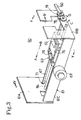
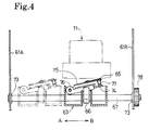
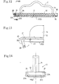
- Fig. 2 is a perspective view of a seal plate (referred to as a marked seal plate 10) where character, or line drawing portions, 6 are formed at the seal face portion 2 in a mirror image shape of a character, such as a predetermined letter or figure, which are created by a marking device 60 as shown in Fig. 3 through Fig. 5. That is, between two end walls 61A and 61B of a frame 61 are mounted, a guide rod 64 extending in the left and right directions of Fig. 3 for guiding a carriage 63 and a head switch rod 67 extending in the left and right directions of Fig. 4 for guiding the carriage 63 and operating a cam 66 that elevates a thermal head 65 mounted on the carriage 63.
- the cam 66 is mounted unpivotably with respect to the head switch rod 67 and frictionally in the axial direction.
- the head switch rod 67 is rotatably supported by bearings 73 to the two end walls 61A and 61B.
- the seal plate 1 is mounted onto a lower face of a stamp device 11, discussed later in detail, and positioned and fixed above a position where the carriage 63 passes, as illustrated in Figs. 4 and 5.
- the carriage 63 is supported by the guide rod 64 and the head switch rod 67 so as to be movable in the left and right directions with respect to Fig. 4.
- a rack 68 is fixed to a front end of the carriage 63 integrally or via a suitable fixing means.
- Power is transmitted from a drive pinion 70 of a bi-directionally rotatable drive motor 69 fixed to a front face wall 61C of the frame 61, to a gear 72 in mesh with a reduction gear train 71 arranged on the back face of the front face wall 61C.
- the meshed gear 72 meshes with the rack 68 by which the carriage 63 can be moved in the left and the right directions (designated by arrows A and B in Fig. 3 and Fig. 4).
- a cam contact plate 74 and a head heat radiating plate 75 are mounted on the carriage 63 and can pivot in the upward and downward directions via a support shaft 76.
- the thermal head 65 is fixed to an upper end side of the upper face of the head heat radiating plate 75, as shown in Fig. 4. Further, the head heat radiating plate 75 is always elastically urged by an urging spring 77 interposed between the upper face of the cam contact plate 74 and the back face of the head heat radiating plate 75.
- the attitude of the cam 66 formed in an elliptical shape such that it can be brought into contact with a lower face of the cam contact plate 74, can be changed by pivoting the head switch rod 67 in directions represented by arrows C and D in Fig. 3.
- the head heat radiating plate 75 attached with the thermal head 65 is released downwardly.
- the cam 66 is erected as shown in Fig. 4
- the head heat radiating plate 75 is pivoted upwardly via the cam contact plate 74 and the urging spring 77 whereby the thermal head 65 is brought into press contact with the lower face of the seal plate 1 whose position has been fixed as described above.
- the head switch rod 67 is pivoted in directions C or D by means of a gear 78 attached to an end portion of the head switch rod 67, a gear 79, the axis of which is supported by the end wall 61B, and a lever 80 for pivoting the gear 79.
- the thermal head 65 structured similar to a thermal head in a conventionally well-known thermal printer, in which, for example, 96 pieces of dot-like heat generating elements are arranged in one row in a direction orthogonal to the direction A of Figs. 3 and 4.
- the row length of the dot-like heat generating elements is set to be longer than a lateral width dimension of the seal plate 1.
- a marked seal plate 10 can be manufactured in which the character portions 6 remain as portions, which have not been melted and solidified, through which ink can permeate while the other portions are the melted and solidified portion 7 through which ink cannot permeate.
- Such a marked seal plate 10 is illustrated in Fig. 2.
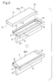
- Fig. 6 through Fig. 9 illustrate a first embodiment of the stamp device 11 in which a handle portion 14 is formed integrally with or separately from a supporter 12.
- the supporter 12 has a square shape in plane view for supporting the back face of the seal plate 1.
- the seal plate 1 also has a substantially square flat plate shape in plane view.
- a pair of engaging claws 13 extend in the longitudinal direction along a seal plate support face 12A of the supporter 12 and are provided to be in parallel with opposite edge faces 1A of the seal plate 1.
- the opposite edge faces 1A are elastically engaged by the engaging claws 13 and a recessed groove stopper portion 15 is provided for receiving therein and holding one end portion 1B of the seal plate 1, which end portion extends orthogonal to the edge faces 1A.
- an inclined face 16 is formed at the recessed groove stopper portion 15 on one end of the seal plate supporting face 12A of the supporter 12.
- a pressure sensitive weak adhesive layer 17 is provided on a portion of the seal plate supporting face 12A of the supporter 12 along the longitudinal direction thereof.
- the one end portion 1B of the seal plate 1 is inserted into the recessed groove engaging portion 15 by sliding it along the inclined face and the seal plate is inserted between the pair of engaging claws 13 such that the back face of the seal plate 1 is pressed to the pressure sensitive weak adhesive layer 17.
- the opposite side edge faces 1A of the seal plate 1 or side edge corner portions of the seal face portion 2 of the seal plate 1 can be elastically engaged by the pair of engaging claws 13.
- the back face of the seal plate 1 is fixed onto a portion of the seal plate supporting face 12A of the supporter 12 by the pressure sensitive weak adhesive layer 17 while the opposite edge faces 1A of the seal plate 1 are engaged by the pair of engaging claws 13 and further, the one end portion 1B of the seal plate is held by the recessed groove stopper portion 15. Accordingly, the seal plate 1 is removably mounted to the supporter 12 with certainty and is secured until removed.
- the pair of engaging claws 13 may be formed continuously in the longitudinal direction of the seal plate 1 (refer to Fig. 6), or intermittently whereby portions of the seal plate are not engaged. Additionally, a through hole 18 penetrating the surface and the back face of a thick portion of the supporter 12 may be perforated at the recessed groove stopper portion 15.
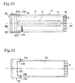
- Fig. 10 through Fig. 17 illustrate a second embodiment of the invention showing flat plate-shaped seal plate 1 having a structure similar to the above-described one and supporter 12 for supporting the back face of the seal plate 1.
- the supporter 12 is provided with the pair of engaging claws 13 extending in the longitudinal direction thereof for pinching the opposite side edge faces 1A of the seal plate 1 and the recessed groove stopper portion 15 for holding the one end portion 1B of the seal plate 1 by receiving the one end portion 1B therein.
- the supporter 12 is further provided with a pivoting pinching device 20 at an end portion 1C opposite to the end portion 1B having the recessed groove stopper portion 15 for pinching the other end portion of the seal plate 1 between the pivoting pinching device 20 and the seal plate supporting face 12A.
- the pivoting pinching device 20 is formed in substantially a "C" shape in plane view and is provided with a connecting piece 20C for connecting handles 20A on two sides and hold pieces 20B at both end portions 1B, 1C of the connecting piece 20C.
- the pivoting pinching device 20 is pivotably mounted to the other end portion 1C of the supporter 12 at portions of the two handles 20A via support shafts 21.
- the opposite end faces 1A of the seal plate 1 are engaged with the pair of engaging claws 13 and further, the one end portion 1B of the seal plate received by the recessed groove engaging portion 15 and held therein, whereas the other end portion 1C of the seal plate 1 is pinched by the hold pieces 20B of the pivoting pinching device 20 such that it is pushed into the notched groove 24 (refer to Fig. 12).
- the three surrounding sides of the seal plate 1 can be held by the supporter 12 and therefore, the seal plate 1 is removably mounted to the supporter 12 with certainty and is secured until removed.
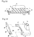
- the seal plate 1 when the pair of engaging claws 13 are omitted, as illustrated in Fig. 16, the seal plate 1 can be pressed to the seal plate supporting face 12A of the supporter 12 by the recessed groove stopper portion 15 and by pushing the corner portion of the seal plate 1 opposed to the recessed groove stopper portion 15 by the hold pieces 20B of the pivoting pinching device 20. Further, as illustrated in Fig. 17, the force for pressing and pinching the other end portion 1C of the seal plate 1 to the seal plate supporting face 12A of the supporter 12 can be increased by providing stopper projections 25 on the respective hold pieces 20B.
- pinching bodies 26 are pivotally provided at both end portions of the supporter 12 and the end portions 1B, 1C of the seal plate 1 are pinched by the two pivoting pinching bodies 26 by being pushed onto the seal plate supporting face 12A of the supporter 12, as illustrated in Fig. 19.
- Both pinching bodies 26 have an L-shaped section and are pivotably connected to end brackets 27 of the supporter 12 via pins 28.
- a lower end pushing piece 26A of the pinching body 26 pinches the end portion of the seal plate 1 by pushing it toward the seal plate supporting face 12A of the supporter 12 and a spring 29 in a bent shape is provided integrally to a side face of the supporter 12 between the end brackets 27.
- a width H1 of the head heat radiating plate 75 which is equal in length to the row of dot-like heat generating elements in the thermal head 65, is set a little wider than the width of the seal face portion 2 of the seal plate 1.
- the seal plate 1 when the seal plate 1 is mounted to the supporter 12, in the marking operation the seal plate 1 does not shift from the supporter 12 even if the seal face portion 2 of the seal plate 1 is rubbed by the thermal head 65. Thus, its position can be maintained with certainty and the marking operation can firmly be carried out.
- the finished, marked seal plate 10 may be removed from the supporter 12 by methods particular to the above-described respective embodiments.
- the marked seal plate 10 can be manufactured easily and swiftly.
- the finished marked seal plate 10 is pushed onto an ink impregnating pad (not illustrated) while being mounted to each of the stamp devices 11 or ink is absorbed to the inside from the character portions 6 which are the unmelted portions through which ink cannot permeate and thereafter, sealing is conducted on record medium such as paper.
Landscapes
- Manufacture Or Reproduction Of Printing Formes (AREA)
Applications Claiming Priority (2)
| Application Number | Priority Date | Filing Date | Title |
|---|---|---|---|
| JP119088/96 | 1996-05-14 | ||
| JP8119088A JPH09300800A (ja) | 1996-05-14 | 1996-05-14 | スタンプ装置 |
Publications (1)
| Publication Number | Publication Date |
|---|---|
| EP0807532A1 true EP0807532A1 (fr) | 1997-11-19 |
Family
ID=14752601
Family Applications (1)
| Application Number | Title | Priority Date | Filing Date |
|---|---|---|---|
| EP97303234A Withdrawn EP0807532A1 (fr) | 1996-05-14 | 1997-05-13 | Dispositif de tampon |
Country Status (3)
| Country | Link |
|---|---|
| US (1) | US5829352A (fr) |
| EP (1) | EP0807532A1 (fr) |
| JP (1) | JPH09300800A (fr) |
Families Citing this family (9)
| Publication number | Priority date | Publication date | Assignee | Title |
|---|---|---|---|---|
| US6276272B1 (en) * | 1996-10-01 | 2001-08-21 | Brother Kogyo Kabushiki Kaisha | Stamp plate producing apparatus for producing stamp plate used in a stamp device |
| US6112662A (en) | 1996-10-16 | 2000-09-05 | Brother Kogyo Kabushiki Kaisha | Stamp unit |
| US6119596A (en) * | 1997-08-04 | 2000-09-19 | M&R Marking Systems, Inc. | Pre-inked marking structures and method of assembling same to a stamped mount |
| KR100689166B1 (ko) * | 1999-07-06 | 2007-03-08 | 부라더 고교 가부시키가이샤 | 스탬프용 도장 부재 및 이를 이용한 스탬프 유닛 |
| US7069853B1 (en) * | 2004-07-24 | 2006-07-04 | Solomon Jr John J | Ergonomically improved multiple surface stamp |
| JP6205731B2 (ja) * | 2012-07-20 | 2017-10-04 | シヤチハタ株式会社 | 多孔質印判の製造方法、多孔質印判、および多孔質印判の製造装置 |
| JP5846175B2 (ja) * | 2013-09-20 | 2016-01-20 | カシオ計算機株式会社 | 印面製版装置、印面材サイズ検出方法、媒体ホルダおよび媒体ホルダ製造方法 |
| JP5900444B2 (ja) | 2013-09-20 | 2016-04-06 | カシオ計算機株式会社 | 印面製版装置、印面材寸法検出方法、媒体ホルダおよび媒体ホルダ製造方法 |
| JP5885082B2 (ja) * | 2013-10-09 | 2016-03-15 | カシオ計算機株式会社 | 印面形成装置及び印面形成方法 |
Citations (5)
| Publication number | Priority date | Publication date | Assignee | Title |
|---|---|---|---|---|
| US2176160A (en) * | 1938-05-10 | 1939-10-17 | Jr Otto Uhl | Hand printing stamp |
| US2899895A (en) * | 1959-08-18 | Rubber stamp | ||
| US5048415A (en) * | 1990-05-31 | 1991-09-17 | Shiny Shih | Stamp combination |
| JPH0558015A (ja) * | 1991-09-03 | 1993-03-09 | Mitsubishi Pencil Co Ltd | レーザー加工によるゴム印の製作法 |
| EP0644059A1 (fr) * | 1993-03-15 | 1995-03-22 | King Jim Co., Ltd. | Appareil de fabrication de sceaux |
Family Cites Families (12)
| Publication number | Priority date | Publication date | Assignee | Title |
|---|---|---|---|---|
| US1191820A (en) * | 1915-11-11 | 1916-07-18 | Pannier Bros Stamp Company | Stamp. |
| US1608541A (en) * | 1925-11-04 | 1926-11-30 | Superior Type Company | Rubber-stamp base |
| US2966116A (en) * | 1960-02-02 | 1960-12-27 | Johnson & Son Inc S C | Resilient hand stamp |
| US3282209A (en) * | 1965-03-01 | 1966-11-01 | Muskin Nathan | Sliding section stamp |
| US3973495A (en) * | 1970-07-31 | 1976-08-10 | Vuestamp International Proprietary Limited | Hand stamp |
| JPS5623095Y2 (fr) * | 1972-06-26 | 1981-05-29 | ||
| JPS6021551B2 (ja) * | 1979-08-14 | 1985-05-28 | 東芝テック株式会社 | ラベルプリンタの品名印装置 |
| US4441422A (en) * | 1982-01-08 | 1984-04-10 | Lionel Dreeben | Capillary stencil printer with improved replenishment of the printing pad and re-inking of the reservoir |
| US5392711A (en) * | 1992-10-16 | 1995-02-28 | Kaitec Co., Ltd. | Method of manufacturing a printing plate |
| US5577444A (en) * | 1993-06-22 | 1996-11-26 | Yamahachi Chemical Co., Ltd. | Hand stamp |
| WO1995009730A1 (fr) * | 1993-10-02 | 1995-04-13 | Mitsubishi Pencil Kabushiki Kaisha | Procede pour fabriquer une plaque en forme de tampon, et tampon ainsi obtenu |
| JP3020416B2 (ja) * | 1993-12-28 | 2000-03-15 | 三菱鉛筆株式会社 | スタンプの製造法 |
-
1996
- 1996-05-14 JP JP8119088A patent/JPH09300800A/ja active Pending
-
1997
- 1997-04-07 US US08/826,722 patent/US5829352A/en not_active Expired - Fee Related
- 1997-05-13 EP EP97303234A patent/EP0807532A1/fr not_active Withdrawn
Patent Citations (5)
| Publication number | Priority date | Publication date | Assignee | Title |
|---|---|---|---|---|
| US2899895A (en) * | 1959-08-18 | Rubber stamp | ||
| US2176160A (en) * | 1938-05-10 | 1939-10-17 | Jr Otto Uhl | Hand printing stamp |
| US5048415A (en) * | 1990-05-31 | 1991-09-17 | Shiny Shih | Stamp combination |
| JPH0558015A (ja) * | 1991-09-03 | 1993-03-09 | Mitsubishi Pencil Co Ltd | レーザー加工によるゴム印の製作法 |
| EP0644059A1 (fr) * | 1993-03-15 | 1995-03-22 | King Jim Co., Ltd. | Appareil de fabrication de sceaux |
Non-Patent Citations (1)
| Title |
|---|
| PATENT ABSTRACTS OF JAPAN vol. 017, no. 368 (M - 1443) 12 July 1993 (1993-07-12) * |
Also Published As
| Publication number | Publication date |
|---|---|
| JPH09300800A (ja) | 1997-11-25 |
| US5829352A (en) | 1998-11-03 |
Similar Documents
| Publication | Publication Date | Title |
|---|---|---|
| US5816160A (en) | Stamp unit capable of detachably holding stamp plate formed with stamp image | |
| US5829352A (en) | Stamp device having seal plate and support portion | |
| US5741459A (en) | Process for preparing stamp | |
| US5595112A (en) | Stamp assembly and stamp unit including the stamp assembly and a perforation device | |
| EP0655342B1 (fr) | Dispositif de timbrage utilisant du papier stencil thermosensible et son procédé de perforation | |
| EP0659577B1 (fr) | Imprimante thermique pour dispositif de tampon | |
| US6229556B1 (en) | Printer and method of using same to print on thermoplastic medium | |
| JPH10120949A (ja) | スタンプ装置 | |
| WO1999030907A1 (fr) | Imprimante a tete thermique et procede d'impression sur support thermoplastique utilisant ladite tete | |
| EP0723871A2 (fr) | Dispositif de perforation d'une unité de marquage | |
| JP2600805Y2 (ja) | スタンプ作成装置 | |
| JP3675032B2 (ja) | 回転式スタンプ装置 | |
| JPH09300799A (ja) | スタンプ装置 | |
| JPH09300801A (ja) | スタンプ装置 | |
| JP2939969B2 (ja) | カットシート状感熱紙カセット | |
| JPH09309256A (ja) | 回転式スタンプ装置 | |
| JPH09300798A (ja) | スタンプ装置 | |
| JP3045240U (ja) | スタンプ体 | |
| JP2924646B2 (ja) | スタンプ装置 | |
| JP2932986B2 (ja) | 感熱性孔版作製方法 | |
| JP3125650B2 (ja) | 孔版印刷用原板 | |
| JP3215589B2 (ja) | スタンプユニット用加熱印字装置 | |
| JPH09309257A (ja) | スタンプ作成装置 | |
| JPH10217422A (ja) | スタンプユニットの穿孔装置 | |
| JPH09309253A (ja) | 回転式スタンプ装置 |
Legal Events
| Date | Code | Title | Description |
|---|---|---|---|
| PUAI | Public reference made under article 153(3) epc to a published international application that has entered the european phase |
Free format text: ORIGINAL CODE: 0009012 |
|
| AK | Designated contracting states |
Kind code of ref document: A1 Designated state(s): AT BE CH DE FR GB IT LI |
|
| STAA | Information on the status of an ep patent application or granted ep patent |
Free format text: STATUS: THE APPLICATION IS DEEMED TO BE WITHDRAWN |
|
| 18D | Application deemed to be withdrawn |
Effective date: 19980520 |