EP0807545B1 - Actuating device for an operating mechanism in motor vehicle - Google Patents
Actuating device for an operating mechanism in motor vehicle Download PDFInfo
- Publication number
- EP0807545B1 EP0807545B1 EP97104996A EP97104996A EP0807545B1 EP 0807545 B1 EP0807545 B1 EP 0807545B1 EP 97104996 A EP97104996 A EP 97104996A EP 97104996 A EP97104996 A EP 97104996A EP 0807545 B1 EP0807545 B1 EP 0807545B1
- Authority
- EP
- European Patent Office
- Prior art keywords
- actuating
- potentiometer
- range
- setting range
- ranges
- Prior art date
- Legal status (The legal status is an assumption and is not a legal conclusion. Google has not performed a legal analysis and makes no representation as to the accuracy of the status listed.)
- Expired - Lifetime
Links
Images
Classifications
-
- B—PERFORMING OPERATIONS; TRANSPORTING
- B60—VEHICLES IN GENERAL
- B60J—WINDOWS, WINDSCREENS, NON-FIXED ROOFS, DOORS, OR SIMILAR DEVICES FOR VEHICLES; REMOVABLE EXTERNAL PROTECTIVE COVERINGS SPECIALLY ADAPTED FOR VEHICLES
- B60J7/00—Non-fixed roofs; Roofs with movable panels, e.g. rotary sunroofs
- B60J7/02—Non-fixed roofs; Roofs with movable panels, e.g. rotary sunroofs of sliding type, e.g. comprising guide shoes
- B60J7/04—Non-fixed roofs; Roofs with movable panels, e.g. rotary sunroofs of sliding type, e.g. comprising guide shoes with rigid plate-like element or elements, e.g. open roofs with harmonica-type folding rigid panels
- B60J7/057—Driving or actuating arrangements e.g. manually operated levers or knobs
- B60J7/0573—Driving or actuating arrangements e.g. manually operated levers or knobs power driven arrangements, e.g. electrical
-
- G—PHYSICS
- G05—CONTROLLING; REGULATING
- G05B—CONTROL OR REGULATING SYSTEMS IN GENERAL; FUNCTIONAL ELEMENTS OF SUCH SYSTEMS; MONITORING OR TESTING ARRANGEMENTS FOR SUCH SYSTEMS OR ELEMENTS
- G05B19/00—Program-control systems
- G05B19/02—Program-control systems electric
- G05B19/18—Numerical control [NC], i.e. automatically operating machines, in particular machine tools, e.g. in a manufacturing environment, so as to execute positioning, movement or co-ordinated operations by means of program data in numerical form
- G05B19/19—Numerical control [NC], i.e. automatically operating machines, in particular machine tools, e.g. in a manufacturing environment, so as to execute positioning, movement or co-ordinated operations by means of program data in numerical form characterised by positioning or contouring control systems, e.g. to control position from one programmed point to another or to control movement along a programmed continuous path
- G05B19/33—Numerical control [NC], i.e. automatically operating machines, in particular machine tools, e.g. in a manufacturing environment, so as to execute positioning, movement or co-ordinated operations by means of program data in numerical form characterised by positioning or contouring control systems, e.g. to control position from one programmed point to another or to control movement along a programmed continuous path using an analogue measuring device
- G05B19/35—Numerical control [NC], i.e. automatically operating machines, in particular machine tools, e.g. in a manufacturing environment, so as to execute positioning, movement or co-ordinated operations by means of program data in numerical form characterised by positioning or contouring control systems, e.g. to control position from one programmed point to another or to control movement along a programmed continuous path using an analogue measuring device for point-to-point control
- G05B19/351—Numerical control [NC], i.e. automatically operating machines, in particular machine tools, e.g. in a manufacturing environment, so as to execute positioning, movement or co-ordinated operations by means of program data in numerical form characterised by positioning or contouring control systems, e.g. to control position from one programmed point to another or to control movement along a programmed continuous path using an analogue measuring device for point-to-point control the positional error is used to control continuously the servomotor according to its magnitude
Definitions
- the invention relates to a device for actuation an adjustment drive arranged in a vehicle.
- a potentiometer includes, which for Setpoint specification is used. It is advisable different slope of the characteristic curve depending on the area of the potentiometer to allow a flexible adjustment to achieve different stress cases. There is a distinction, particularly with sunroofs between lifting and sliding positions is important. With that two adjustment ranges of the potentiometer, in which a setpoint is specified with different accuracy can be. This means that only analog setpoints are sent to the Control device forwarded. Switching or push button functions cannot be carried out via the potentiometer.
- the device according to the invention for actuating a a vehicle arranged actuator is located Based on the task, analog setpoint and push button function to integrate. This object is achieved by the features of claim 1 solved.
- In the first setting range of the potentiometer is the well-known analog setpoint specification realized.
- a second setting range is a switching function assigned, whereby a button or switch are replaced can. This is particularly the case with sunroofs Double functionality particularly useful because of the area code a specific sunroof position in the first setting range Approach taking into account the clamping force limit while the sunroof is in the second setting range without considering a clamping force limitation in Jog mode can be adjusted.
- the potentiometer of the device according to the invention can be by Manually operate the control element. This potentiometer requires three leads. Did you want switching and Realizing the potentiometer function separately would at least be four lines required. By the device according to the invention cabling and space requirements are reduced for a corresponding fitting.
- a practical one Design of the device according to the invention provides that the at least two adjustment ranges are different from each other can be distinguished that the potentiometer voltage with a characteristic of the range limit Reference voltage is compared. Falls below or exceeds the potentiometer voltage this reference voltage, it will recognized by control electronics and the adjustment drive as controlled in jog mode. For example a deactivation of the closing force limit coupled his.
- the first adjustment range the entire adjustment range where however, the second setting range by at least one End stop is formed. This allows in the first Achieve a precise setpoint setting range. For the Triggering a switching function is therefore only a minor one Area needed, what the clarity of operation benefits.
- the device according to the invention is pre-selected second setting range against overcoming a spring force. This allows a push button function with a simple design realize. Especially when used in Motor vehicles are thus ensured that Vibrations do not trigger a switching function.
- the first setting range must be selected, which is the normal operating mode corresponds.
- the adjustment drive should only be used in exceptional cases of the sunroof can be operated in jog mode.
- the control element is a further useful embodiment either as a rotary knob or as a slide lever.
- the device according to the invention is used in particular for actuating one arranged in a motor vehicle electric adjustment drive for window regulators and Sunroofs. Especially in the case of motor vehicles Meaning if several functions in one control element can be integrated to increase ease of use and to save space. More beneficial Refinements result from the description.
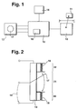
- FIG. 1 shows an embodiment of a device according to the invention and FIG. 2 a Design of the potentiometer according to the invention.
- An adjustment drive 10 moves a part 11.
- a Control electronics 12 include a closing force limitation 16 and processes signals of a position detection 14 and a potentiometer that can be actuated via an operating element 17 13. According to the potentiometer setting, the Control electronics 12 the adjustment drive 10 switching signals Available.
- Figure 2 encloses a second setting range 22 a first setting range 21. A selection of the second Adjustment range 22 takes place against the control element 17 a force applied by a spring 18. Depending on the position of the control element 17 changes a voltage 19 of the potentiometer 13.
- the control element 17 provides at least two adjustment ranges 21, 22 of the potentiometer 13 adjustable.
- the adjustment drive 10 is, for example, in the Jog mode controlled. Especially with window regulators or Sunroofs it is useful to do a typing operation without Closing force limit 16 to realize. This allows for the commissioning of the adjustment drive 10 standardization runs to be carried out on the basis of the measured values of a Standardization run limit values for the closing force limit 16 to specify or the position of the actuator normalize. Only then is the first one selected Setting range 21 taking into account the Closing force limit 16 possible.
- the control element 17 can be in the first setting range 21 continuous or Specify discrete values.
- the voltage 19 changes corresponding. This voltage 19 are target positions of the Part 11 assigned. Under consideration of Actual position values, which position detection 14 determines, the target-actual difference is corrected to zero.
- the first setting range 21 it is conceivable that different slopes of the potentiometer characteristic are implemented by appropriate wiring. Thereby can be adapted to different Carry out load profiles.
- first and second Setting range 21, 22 can be recognized. Basically this is via a switch which can be actuated by the control element 17 possible. It is particularly useful, however Range limit by comparing the voltage 19 with one for the setting range limit characteristic reference voltage to investigate. If this is in accordance with the execution of the Potentiometers 13 specified reference voltage over or undershot, the control electronics 12 recognizes that a selection of the first or the second adjustment range 21, 22 is done. Here are only three feed lines to the Potentiometer 13 required. It is from one Supply voltage fed, the voltage 19 supplies Measure of the position of the control element 17.
- the end positions are particularly suitable for the second Setting range 22 on. With a rotary knob with two end positions these could be used to move the actuator in to use one way and the other. To one Bring about a change in direction of the adjustment drive 10, without an operating mode that corresponds to the first setting range 21st assigned to trigger, positions the Control electronics 12 only when the control element 17 for a specified time interval remains in its position. The the same problem also arises with one Sliding potentiometer.
- Another embodiment of the device according to the invention is characterized in that a preselection of the second Setting range 22 only against overcoming a force of the spring 18 is applied takes place. This will turn on easily implemented a push button function. Will that Operating element 17 released, the spring 18 presses it back into the first setting area 21. Especially at the Operation of a sunroof is the first setting range 21 the normal operating mode there. Should only be used in exceptional situations the first setting range 21 can be left, for example if the closing force limit 16 is to be bypassed. There however, if security is endangered, it is necessary the actuation of the control element 17 against the spring force Increased attention.
- the inventive device for Actuation of an electrical arranged in a vehicle Actuator is preferred for Window lifters or sunroofs.
Landscapes
- Engineering & Computer Science (AREA)
- Human Computer Interaction (AREA)
- Manufacturing & Machinery (AREA)
- Physics & Mathematics (AREA)
- General Physics & Mathematics (AREA)
- Automation & Control Theory (AREA)
- Mechanical Engineering (AREA)
- Power-Operated Mechanisms For Wings (AREA)
- Axle Suspensions And Sidecars For Cycles (AREA)
Description
Die Erfindung geht aus von einer Vorrichtung zum Betätigen eines in einem Fahrzeug angeordneten Verstellantriebs. Aus der gattungsbildenden DE-A 33 24 107 ist eine Betätigungseinrichtung für Verschiebe-Hebdächer in Kraftfahrzeugen bekannt, die eine Beschreibung eines Potentiometers beinhaltet, welches zur Sollwertvorgabe eingesetzt wird. Dabei ist es zweckmäßig, bereichsabhängig unterschiedliche Steilheiten der Kennlinie des Potentiometers vorzugeben, um so eine flexible Anpassung an unterschiedliche Belastungsfälle zu erreichen. Insbesondere bei Schiebedächern ist eine Unterscheidung zwischen Hebe- und Schiebestellung von Bedeutung. Damit sind zwei Stellbereiche des Potentiometers realisiert, in denen mit unterschiedlicher Genauigkeit ein Sollwert vorgegeben werden kann. Es werden damit nur analoge Sollwerte an die Regeleinrichtung weitergeleitet. Schalt- bzw. Tastfunktionen können über das Potentiometer nicht ausgeführt werden. The invention relates to a device for actuation an adjustment drive arranged in a vehicle. From the generic DE-A 33 24 107 is an actuator for Sliding sunroofs in motor vehicles are known, the one Description of a potentiometer includes, which for Setpoint specification is used. It is advisable different slope of the characteristic curve depending on the area of the potentiometer to allow a flexible adjustment to achieve different stress cases. There is a distinction, particularly with sunroofs between lifting and sliding positions is important. With that two adjustment ranges of the potentiometer, in which a setpoint is specified with different accuracy can be. This means that only analog setpoints are sent to the Control device forwarded. Switching or push button functions cannot be carried out via the potentiometer.
Der erfindungsgemäßen Vorrichtung zum Betätigen eines in einem Fahrzeug angeordneten Verstellantriebs liegt die Aufgabe zugrunde, analoge Sollwertvorgabe und Tastfunktion zu integrieren. Diese Aufgabe wird erfindungsgemäß durch die Merkmale des Anspruchs 1 gelöst. Dabei sind den zumindest zwei Stellbereichen des Potentiometers unterschiedliche Funktionen zugeordnet. Im ersten Stellbereich des Potentiometers ist die hinlänglich bekannte analoge Sollwertvorgabe realisiert. Einem zweiten Stellbereich ist eine Schaltfunktion zugeordnet, wodurch ein Taster oder Schalter ersetzt werden kann. Insbesondere bei Schiebedächern ist diese Doppelfunktionalität besonders zweckmäßig, da durch Vorwahl im ersten Stellbereich eine bestimmte Schiebedachposition unter Berücksichtigung der Schließkraftbegrenzung anzufahren ist, während in dem zweiten Stellbereich das Schiebedach ohne Berücksichtigung einer Schließkraftbegrenzung im Tippbetrieb verstellt werden kann. Das Potentiometer der erfindungsgemäßen Vorrichtung läßt sich durch ein Bedienelement manuell betätigen. Dieses Potentiometer benötigt drei Zuleitungen. Wollte man Schalt- und Potentiometerfunktion getrennt realisieren, wären zumindest vier Leitungen nötig. Durch die erfindungsgemäße Vorrichtung reduziert sich der Verkabelungsaufwand und der Platzbedarf für eine entsprechende Armatur. Eine zweckmäßige Ausgestaltung der erfindungsgemäßen Vorrichtung sieht vor, daß die zumindest zwei Stellbereiche dadurch voneinander unterschieden werden können, daß die Potentiometerspannung mit einer für die Stellbereichsgrenze charakteristischen Referenzspannung verglichen wird. Unter- oder überschreitet die Potentiometerspannung diese Referenzspannung, wird dies von einer Steuerelektronik erkannt und der Verstellantrieb wie im Tippbetrieb angesteuert. Daran könnte beispielsweise eine Deaktivierung der Schließkraftbegrenzung gekoppelt sein. In einer weiteren Ausgestaltung der Erfindung umfaßt der erste Stellbereich den gesamten Stellbereich, wo hingegen der zweite Stellbereich durch zumindest einen Endanschlag gebildet ist. Dadurch läßt sich im ersten Stellbereich eine genaue Sollwertvorgabe erzielen. Für das Auslösen einer Schaltfunktion ist damit nur ein geringer Bereich vonnöten, was der Übersichtlichkeit der Bedienung zugute kommt. In einer zweckmäßigen Ausführungsform der erfindungsgemäßen Vorrichtung erfolgt eine Vorwahl eines zweiten Stellbereichs gegen Überwindung einer Federkraft. Damit läßt sich mit einfacher Bauform eine Tastfunktion realisieren. Insbesondere bei der Verwendung in Kraftfahrzeugen ist damit sichergestellt, daß durch Rüttelbewegungen nicht eine Schaltfunktion ausgelöst wird. Bei der Bedienung von Schiebedächern wird in der Regel der erste Stellbereich angewählt sein, was der Normalbetriebsart entspricht. Nur in Ausnahmefällen soll der Verstellantrieb des Schiebedachs im Tippbetrieb betätigt werden. Die Verwendung einer Feder reduziert Fehlauslösungen. In weiteren zweckmäßigen Ausgestaltungen ist das Bedienelement entweder als Drehknopf oder als Schiebehebel ausgeführt. Besondere Verwendung findet die erfindungsgemäße Vorrichtung zum Betätigen eines in einem Kraftfahrzeug angeordneten elektrischen Verstellantriebs für Fensterheber und Schiebedächer. Insbesondere bei Kraftfahrzeugen ist es von Bedeutung, wenn mehrere Funktionen in einem Bedienelement integriert werden können, um so den Bedienkomfort zu erhöhen und eine Platzersparnis zu erreichen. Weitere vorteilhafte Ausgestaltungen ergeben sich aus der Beschreibung.The device according to the invention for actuating a a vehicle arranged actuator is located Based on the task, analog setpoint and push button function to integrate. This object is achieved by the features of claim 1 solved. The at least two adjustment ranges of the Potentiometers assigned different functions. In the first setting range of the potentiometer is the well-known analog setpoint specification realized. A second setting range is a switching function assigned, whereby a button or switch are replaced can. This is particularly the case with sunroofs Double functionality particularly useful because of the area code a specific sunroof position in the first setting range Approach taking into account the clamping force limit while the sunroof is in the second setting range without considering a clamping force limitation in Jog mode can be adjusted. The potentiometer of the device according to the invention can be by Manually operate the control element. This potentiometer requires three leads. Did you want switching and Realizing the potentiometer function separately would at least be four lines required. By the device according to the invention cabling and space requirements are reduced for a corresponding fitting. A practical one Design of the device according to the invention provides that the at least two adjustment ranges are different from each other can be distinguished that the potentiometer voltage with a characteristic of the range limit Reference voltage is compared. Falls below or exceeds the potentiometer voltage this reference voltage, it will recognized by control electronics and the adjustment drive as controlled in jog mode. For example a deactivation of the closing force limit coupled his. In a further embodiment of the invention the first adjustment range the entire adjustment range where however, the second setting range by at least one End stop is formed. This allows in the first Achieve a precise setpoint setting range. For the Triggering a switching function is therefore only a minor one Area needed, what the clarity of operation benefits. In an expedient embodiment of the The device according to the invention is pre-selected second setting range against overcoming a spring force. This allows a push button function with a simple design realize. Especially when used in Motor vehicles are thus ensured that Vibrations do not trigger a switching function. When operating sunroofs, the first setting range must be selected, which is the normal operating mode corresponds. The adjustment drive should only be used in exceptional cases of the sunroof can be operated in jog mode. The Using a spring reduces false trips. In The control element is a further useful embodiment either as a rotary knob or as a slide lever. The device according to the invention is used in particular for actuating one arranged in a motor vehicle electric adjustment drive for window regulators and Sunroofs. Especially in the case of motor vehicles Meaning if several functions in one control element can be integrated to increase ease of use and to save space. More beneficial Refinements result from the description.
Es zeigen Figur 1 ein Ausführungsbeispiel einer erfindungsgemäßen Vorrichtung und Figur 2 eine erfindungsgemäße Ausgestaltung des Potentiometers. 1 shows an embodiment of a device according to the invention and FIG. 2 a Design of the potentiometer according to the invention.
Ein Verstellantrieb 10 bewegt ein Teil 11. Eine
Steuerelektronik 12 beinhaltet eine Schließkraftbegrenzung
16 und verarbeitet Signale einer Positionserkennung 14 und
eines über ein Bedienelement 17 betätigbaren Potentiometers
13. Gemäß der Potentiometerstellung stellt die
Steuerelektronik 12 dem Verstellantrieb 10 Schaltsignale zur
Verfügung. Gemäß Figur 2 umschließt ein zweiter Stellbereich
22 einen ersten Stellbereich 21. Eine Anwahl des zweiten
Stellbereichs 22 über das Bedienelement 17 erfolgt gegen
eine von einer Feder 18 aufgebrachten Kraft. Abhängig von
der Stellung des Bedienelements 17 ändert sich eine Spannung
19 des Potentiometers 13.An
Die in den Figuren 1 und 2 gezeigten Anordnungen arbeiten folgendermaßen:The arrangements shown in Figures 1 and 2 work as follows:
Durch das Bedienelement 17 sind zumindest zwei Stellbereiche
21, 22 des Potentiometers 13 einstellbar. Im zweiten
Stellbereich 22 ist eine Schaltfunktion realisiert. Ist die
Anwahl des zweiten Stellbereichs 22 von der Steuerelektronik
12 erkannt, so wird der Verstellantrieb 10 beispielsweise im
Tippbetrieb angesteuert. Insbesondere bei Fensterheber oder
Schiebedächer ist es zweckmäßig, einen Tippbetrieb ohne
Schließkraftbegrenzung 16 zu realisieren. Dadurch können für
die Inbetriebnahme des Verstellantriebs 10 Normierungsläufe
durchgeführt werden, um aufgrund der Meßwerte eines
Normierungslaufsgrenzwerte für die Schließkraftbegrenzung 16
vorzugeben oder die Position des Verstellantriebs zu
normieren. Erst dann ist eine Anwahl des ersten
Stellbereichs 21 unter Berücksichtigung der
Schließkraftbegrenzung 16 möglich. Spricht im Normalbetrieb
die Schließkraftbegrenzung 16 an, und es stoppt daraufhin
der Verstellantrieb 10, so läßt er sich bei Anwahl des
zweiten Stellbereichs 22 ohne Schließkraftbegrenzung 16
bedienen. Durch die integrierte Tippfunktion im
Potentiometer 13 läßt sich ein externer Taster sparen, die
Bedienung wird dadurch übersichtlicher und der
Verkabelungsaufwand reduziert. Über das Bedienelement 17
lassen sich im ersten Stellbereich 21 kontinuierliche oder
diskrete Werte vorgeben. Die Spannung 19 ändert sich
entsprechend. Dieser Spannung 19 sind Sollpositionen des
Teils 11 zugeordnet. Unter Berücksichtigung der
Positionsistwerte, die die Positionserkennung 14 ermittelt,
wird die Soll-Ist-Differenz zu Null ausgeregelt.
Hinsichtlich des ersten Stellbereichs 21 ist es denkbar, daß
unterschiedliche Steilheiten der Potentiometerkennlinie
durch entsprechende Beschaltung realisiert sind. Dadurch
läßt sich eine Anpassung an unterschiedliche
Belastungsverläufe vornehmen.The
Es muß die Bereichsgrenze zwischen ersten und zweitem
Stellbereich 21, 22 erkannt werden. Grundsätzlich ist dies
über einen vom Bedienelement 17 betätigbaren Schalter
möglich. Besonders zweckmäßig ist es jedoch, die
Bereichsgrenze durch Vergleich der Spannung 19 mit einer für
die Stellbereichsgrenze charakteristischen Referenzspannung
zu ermitteln. Wird diese entsprechend der Ausführung des
Potentiometers 13 vorgegebene Referenzspannung über- bzw.
unterschritten, so erkennt die Steuerelektronik 12, daß
eine Anwahl des ersten oder des zweiten Stellbereichs 21, 22
erfolgt ist. Hierbei sind nur drei Zuleitungen zu dem
Potentiometer 13 erforderlich. Es wird von einer
Versorgungsspannung gespeist, die Spannung 19 liefert ein
Maß für die Stellung des Bedienelements 17.There must be the boundary between the first and
Insbesondere die Endlagen bieten sich für den zweiten
Stellbereich 22 an. Bei einem Drehknopf mit zwei Endlagen
könnten diese dazu verwendet werden, den Verstellantrieb in
die eine und in die andere Richtung zu bedienen. Um einen
Richtungswechsel des Verstellantriebs 10 herbeizuführen,
ohne daß eine Betriebsart, die dem ersten Stellbereich 21
zugeordnet ist, auszulösen, positioniert die
Steuerelektronik 12 nur, wenn das Bedienelement 17 für ein
vorgegebenes Zeitintervall in seiner Stellung verharrt. Die
gleiche Problematik ergibt sich ebenfalls bei einem
Schiebepotentiometer.The end positions are particularly suitable for the
Eine weitere Ausgestaltung der erfindungsgemäßen Vorrichtung
ist dadurch gekennzeichnet, daß eine Vorwahl des zweiten
Stellbereichs 22 nur gegen Überwindung einer Kraft, die von
der Feder 18 aufgebracht wird, erfolgt. Dadurch wird auf
einfache Weise eine Tastfunktion realisiert. Wird das
Bedienelement 17 losgelassen, so drückt die Feder 18 es
wieder in den ersten Stellbereich 21. Insbesonders bei der
Bedienung eines Schiebedachs stellt der erste Stellbereich
21 die Normalbetriebsart da. Nur in Ausnahmesituationen soll
der erste Stellbereich 21 verlassen werden, beispielsweise
wenn die Schließkraftbegrenzung 16 umgangen werden soll. Da
hierbei jedoch die Sicherheit gefährdet ist, bedarf es bei
der Betätigung des Bedienelements 17 gegen die Federkraft
erhöhte Aufmerksamkeit. Die erfindungsgemäße Vorrichtung zum
Betätigen eines in einem Fahrzeug angeordneten elektrischen
Verstellantriebs findet bevorzugte Verwendung für
Fensterheber oder Schiebedächer.Another embodiment of the device according to the invention
is characterized in that a preselection of the
Claims (8)
- Device for actuating an electric actuating drive (10) arranged in a vehiclewith a potentiometer (13) which can be actuated manually by means of an operating element, specifies a position of a part (11) moved by the actuating drive (10) and is divided into at least two actuating ranges (21, 22),with an electronic control device (12) which activates the actuating drive (10) as a function of the actuating ranges (21, 22) of the potentiometer (13) and the position inputs, characterized in thatat least in a first actuating range (21) of the potentiometer (13) it is possible to set a position of the moved part (11) continuously or discretely anda switching function is assigned at least to a second actuating range (22) of the potentiometer (13).
- Device according to Claim 1, characterized in that at least one of the actuating ranges (21, 22) is detected by comparison with a voltage (19).
- Device according to Claim 1 or 2, characterized in that the first actuating range (21) covers the entire actuating range and the second actuating range (22) is formed by at least one end stop.
- Device according to one of Claims 1 to 3, characterized in that the second actuating range (22) is preselected against a spring force to be overcome.
- Device according to one of Claims 1 to 4, characterized in that the operating element (17) is embodied as a rotary knob.
- Device according to one of Claims 1 to 4, characterized in that the operating element (17) is embodied as a sliding lever.
- Device according to one of Claims 1 to 6, characterized by its use with a sliding roof.
- Device according to one of Claims 1 to 6, characterized by its use with a window lifter.
Applications Claiming Priority (2)
| Application Number | Priority Date | Filing Date | Title |
|---|---|---|---|
| DE19620106A DE19620106C1 (en) | 1996-05-18 | 1996-05-18 | Device for actuating an adjustment drive arranged in a vehicle |
| DE19620106 | 1996-05-18 |
Publications (2)
| Publication Number | Publication Date |
|---|---|
| EP0807545A1 EP0807545A1 (en) | 1997-11-19 |
| EP0807545B1 true EP0807545B1 (en) | 2000-06-07 |
Family
ID=7794693
Family Applications (1)
| Application Number | Title | Priority Date | Filing Date |
|---|---|---|---|
| EP97104996A Expired - Lifetime EP0807545B1 (en) | 1996-05-18 | 1997-03-25 | Actuating device for an operating mechanism in motor vehicle |
Country Status (3)
| Country | Link |
|---|---|
| EP (1) | EP0807545B1 (en) |
| DE (2) | DE19620106C1 (en) |
| ES (1) | ES2148866T3 (en) |
Families Citing this family (6)
| Publication number | Priority date | Publication date | Assignee | Title |
|---|---|---|---|---|
| DE19747326C2 (en) * | 1997-10-27 | 2003-08-28 | Bosch Gmbh Robert | Motor vehicle folding roof system and method for operating a motor vehicle folding roof system |
| DE19756041B4 (en) * | 1997-12-17 | 2007-06-21 | Robert Bosch Gmbh | Circuit arrangement for controlling a sliding lifting roof of a motor vehicle |
| DE10134813B4 (en) * | 2000-07-20 | 2004-09-23 | Küster Automotive Door Systems GmbH | Control with a control device for controlling / regulating at least the travel of an externally powered actuator of a motor vehicle, in particular for adjusting a window lifter or sunroof |
| DE10347318B4 (en) * | 2003-10-08 | 2007-11-08 | Faurecia Innenraum Systeme Gmbh | Device for fine positioning of adjustable openings in motor vehicles |
| EP2296077B1 (en) | 2009-09-04 | 2017-12-13 | Pepperl + Fuchs GmbH | Method for setting the operational parameters of a sensor and sensor for detecting a physical quantity |
| CN102494601B (en) * | 2011-12-09 | 2013-10-02 | 中国钓具技术标准化(北仑海伯)研究中心 | Method for measuring displacement of household electric window by utilizing potentiometer |
Citations (1)
| Publication number | Priority date | Publication date | Assignee | Title |
|---|---|---|---|---|
| DE3324107A1 (en) * | 1982-09-22 | 1984-03-22 | Webasto-Werk W. Baier GmbH & Co, 8035 Gauting | ACTUATING DEVICE. FOR MOVABLE PARTS, ESPECIALLY FOR SLIDING ROOFS AND SLIDING LIFTING ROOFS |
Family Cites Families (2)
| Publication number | Priority date | Publication date | Assignee | Title |
|---|---|---|---|---|
| DE3829405A1 (en) * | 1988-08-30 | 1990-03-08 | Webasto Ag Fahrzeugtechnik | Actuating device for parts of motor vehicles movable by electric motors |
| NL9002198A (en) * | 1990-10-10 | 1992-05-06 | Vermeulen Hollandia Octrooien | DEVICE FOR OPERATING THE ROOF PANEL OF A SLIDING ROOF OR A SLIDING / LIFTING ROOF OF A MOTOR VEHICLE. |
-
1996
- 1996-05-18 DE DE19620106A patent/DE19620106C1/en not_active Expired - Fee Related
-
1997
- 1997-03-25 DE DE59701834T patent/DE59701834D1/en not_active Expired - Lifetime
- 1997-03-25 EP EP97104996A patent/EP0807545B1/en not_active Expired - Lifetime
- 1997-03-25 ES ES97104996T patent/ES2148866T3/en not_active Expired - Lifetime
Patent Citations (1)
| Publication number | Priority date | Publication date | Assignee | Title |
|---|---|---|---|---|
| DE3324107A1 (en) * | 1982-09-22 | 1984-03-22 | Webasto-Werk W. Baier GmbH & Co, 8035 Gauting | ACTUATING DEVICE. FOR MOVABLE PARTS, ESPECIALLY FOR SLIDING ROOFS AND SLIDING LIFTING ROOFS |
Also Published As
| Publication number | Publication date |
|---|---|
| EP0807545A1 (en) | 1997-11-19 |
| DE19620106C1 (en) | 1997-11-20 |
| DE59701834D1 (en) | 2000-07-13 |
| ES2148866T3 (en) | 2000-10-16 |
Similar Documents
| Publication | Publication Date | Title |
|---|---|---|
| DE3348489C2 (en) | Automobile sunroof operating control | |
| EP1371802A2 (en) | Motor vehicle door lock with electro-mechanically actuated central locking | |
| EP1982812B2 (en) | Control for mixer truck | |
| EP0807545B1 (en) | Actuating device for an operating mechanism in motor vehicle | |
| DE1456457A1 (en) | Push button control for hoists | |
| EP0590227B1 (en) | Stalling detection for direct current motors | |
| EP0608771A1 (en) | Device and method to actuate built-in components in motor véhicles | |
| DE3728008A1 (en) | Actuating device for movable parts for optionally closing and releasing openings, in particular of sliding/lifting roofs of motor vehicles | |
| DE29621794U1 (en) | Adjustment device, in particular for a sliding / lifting roof of a motor vehicle | |
| WO2005036293A1 (en) | Device for fine positioning adjustable openings in motor vehicles | |
| EP1425770B1 (en) | Regulating and control device for electric devices | |
| EP0257538B1 (en) | Switching arrangement in motor vehicles | |
| DE10232280A1 (en) | Motor vehicle door lock with an electromechanical central locking drive | |
| DE102004005705A1 (en) | Automotive seat back rake adjustment button or lever is incorporated within headrest | |
| EP0980084B1 (en) | Electric combination switch | |
| DE10151184A1 (en) | Method for monitoring the reversing process of electrically actuated units | |
| DE102018206935B4 (en) | Control device and method for controlling a window lifter with anti-trap protection for a motor vehicle, and software for carrying out the method | |
| EP3507436A1 (en) | Door handle system for a motor vehicle | |
| DE102017006469B3 (en) | Operating device for adjusting a motor vehicle component and motor vehicle | |
| EP1128516B2 (en) | Method for generating an obstruction signal and obstruction detector | |
| DE10036394B4 (en) | Operating device for an electrically operated sunroof of a motor vehicle | |
| DE102007022345A1 (en) | Brightness controller has dimmer that has control unit with rotary actuator element, and control element designed as push button with processing unit | |
| DE4234261C2 (en) | Door locking device for motor vehicles | |
| EP0478884A1 (en) | Load control apparatus | |
| DE19644920B4 (en) | Device for detecting the position of an actuator of an actuator |
Legal Events
| Date | Code | Title | Description |
|---|---|---|---|
| PUAI | Public reference made under article 153(3) epc to a published international application that has entered the european phase |
Free format text: ORIGINAL CODE: 0009012 |
|
| AK | Designated contracting states |
Kind code of ref document: A1 Designated state(s): DE ES FR GB IT |
|
| 17P | Request for examination filed |
Effective date: 19980519 |
|
| GRAG | Despatch of communication of intention to grant |
Free format text: ORIGINAL CODE: EPIDOS AGRA |
|
| 17Q | First examination report despatched |
Effective date: 19990825 |
|
| GRAG | Despatch of communication of intention to grant |
Free format text: ORIGINAL CODE: EPIDOS AGRA |
|
| GRAH | Despatch of communication of intention to grant a patent |
Free format text: ORIGINAL CODE: EPIDOS IGRA |
|
| GRAH | Despatch of communication of intention to grant a patent |
Free format text: ORIGINAL CODE: EPIDOS IGRA |
|
| GRAA | (expected) grant |
Free format text: ORIGINAL CODE: 0009210 |
|
| AK | Designated contracting states |
Kind code of ref document: B1 Designated state(s): DE ES FR GB IT |
|
| REF | Corresponds to: |
Ref document number: 59701834 Country of ref document: DE Date of ref document: 20000713 |
|
| ITF | It: translation for a ep patent filed | ||
| GBT | Gb: translation of ep patent filed (gb section 77(6)(a)/1977) |
Effective date: 20000816 |
|
| ET | Fr: translation filed | ||
| REG | Reference to a national code |
Ref country code: ES Ref legal event code: FG2A Ref document number: 2148866 Country of ref document: ES Kind code of ref document: T3 |
|
| PLBE | No opposition filed within time limit |
Free format text: ORIGINAL CODE: 0009261 |
|
| STAA | Information on the status of an ep patent application or granted ep patent |
Free format text: STATUS: NO OPPOSITION FILED WITHIN TIME LIMIT |
|
| 26N | No opposition filed | ||
| REG | Reference to a national code |
Ref country code: GB Ref legal event code: IF02 |
|
| PGFP | Annual fee paid to national office [announced via postgrant information from national office to epo] |
Ref country code: DE Payment date: 20150521 Year of fee payment: 19 |
|
| REG | Reference to a national code |
Ref country code: FR Ref legal event code: PLFP Year of fee payment: 20 |
|
| PGFP | Annual fee paid to national office [announced via postgrant information from national office to epo] |
Ref country code: ES Payment date: 20160322 Year of fee payment: 20 |
|
| PGFP | Annual fee paid to national office [announced via postgrant information from national office to epo] |
Ref country code: GB Payment date: 20160322 Year of fee payment: 20 Ref country code: FR Payment date: 20160322 Year of fee payment: 20 |
|
| PGFP | Annual fee paid to national office [announced via postgrant information from national office to epo] |
Ref country code: IT Payment date: 20160318 Year of fee payment: 20 |
|
| REG | Reference to a national code |
Ref country code: DE Ref legal event code: R119 Ref document number: 59701834 Country of ref document: DE |
|
| PG25 | Lapsed in a contracting state [announced via postgrant information from national office to epo] |
Ref country code: DE Free format text: LAPSE BECAUSE OF NON-PAYMENT OF DUE FEES Effective date: 20161001 |
|
| REG | Reference to a national code |
Ref country code: GB Ref legal event code: PE20 Expiry date: 20170324 |
|
| PG25 | Lapsed in a contracting state [announced via postgrant information from national office to epo] |
Ref country code: GB Free format text: LAPSE BECAUSE OF EXPIRATION OF PROTECTION Effective date: 20170324 |
|
| REG | Reference to a national code |
Ref country code: ES Ref legal event code: FD2A Effective date: 20170630 |
|
| PG25 | Lapsed in a contracting state [announced via postgrant information from national office to epo] |
Ref country code: ES Free format text: LAPSE BECAUSE OF EXPIRATION OF PROTECTION Effective date: 20170326 |