EP0807545B1 - Commande pour dispositif d'actionnement pour véhicule - Google Patents
Commande pour dispositif d'actionnement pour véhicule Download PDFInfo
- Publication number
- EP0807545B1 EP0807545B1 EP97104996A EP97104996A EP0807545B1 EP 0807545 B1 EP0807545 B1 EP 0807545B1 EP 97104996 A EP97104996 A EP 97104996A EP 97104996 A EP97104996 A EP 97104996A EP 0807545 B1 EP0807545 B1 EP 0807545B1
- Authority
- EP
- European Patent Office
- Prior art keywords
- actuating
- potentiometer
- range
- setting range
- ranges
- Prior art date
- Legal status (The legal status is an assumption and is not a legal conclusion. Google has not performed a legal analysis and makes no representation as to the accuracy of the status listed.)
- Expired - Lifetime
Links
Images
Classifications
-
- B—PERFORMING OPERATIONS; TRANSPORTING
- B60—VEHICLES IN GENERAL
- B60J—WINDOWS, WINDSCREENS, NON-FIXED ROOFS, DOORS, OR SIMILAR DEVICES FOR VEHICLES; REMOVABLE EXTERNAL PROTECTIVE COVERINGS SPECIALLY ADAPTED FOR VEHICLES
- B60J7/00—Non-fixed roofs; Roofs with movable panels, e.g. rotary sunroofs
- B60J7/02—Non-fixed roofs; Roofs with movable panels, e.g. rotary sunroofs of sliding type, e.g. comprising guide shoes
- B60J7/04—Non-fixed roofs; Roofs with movable panels, e.g. rotary sunroofs of sliding type, e.g. comprising guide shoes with rigid plate-like element or elements, e.g. open roofs with harmonica-type folding rigid panels
- B60J7/057—Driving or actuating arrangements e.g. manually operated levers or knobs
- B60J7/0573—Driving or actuating arrangements e.g. manually operated levers or knobs power driven arrangements, e.g. electrical
-
- G—PHYSICS
- G05—CONTROLLING; REGULATING
- G05B—CONTROL OR REGULATING SYSTEMS IN GENERAL; FUNCTIONAL ELEMENTS OF SUCH SYSTEMS; MONITORING OR TESTING ARRANGEMENTS FOR SUCH SYSTEMS OR ELEMENTS
- G05B19/00—Program-control systems
- G05B19/02—Program-control systems electric
- G05B19/18—Numerical control [NC], i.e. automatically operating machines, in particular machine tools, e.g. in a manufacturing environment, so as to execute positioning, movement or co-ordinated operations by means of program data in numerical form
- G05B19/19—Numerical control [NC], i.e. automatically operating machines, in particular machine tools, e.g. in a manufacturing environment, so as to execute positioning, movement or co-ordinated operations by means of program data in numerical form characterised by positioning or contouring control systems, e.g. to control position from one programmed point to another or to control movement along a programmed continuous path
- G05B19/33—Numerical control [NC], i.e. automatically operating machines, in particular machine tools, e.g. in a manufacturing environment, so as to execute positioning, movement or co-ordinated operations by means of program data in numerical form characterised by positioning or contouring control systems, e.g. to control position from one programmed point to another or to control movement along a programmed continuous path using an analogue measuring device
- G05B19/35—Numerical control [NC], i.e. automatically operating machines, in particular machine tools, e.g. in a manufacturing environment, so as to execute positioning, movement or co-ordinated operations by means of program data in numerical form characterised by positioning or contouring control systems, e.g. to control position from one programmed point to another or to control movement along a programmed continuous path using an analogue measuring device for point-to-point control
- G05B19/351—Numerical control [NC], i.e. automatically operating machines, in particular machine tools, e.g. in a manufacturing environment, so as to execute positioning, movement or co-ordinated operations by means of program data in numerical form characterised by positioning or contouring control systems, e.g. to control position from one programmed point to another or to control movement along a programmed continuous path using an analogue measuring device for point-to-point control the positional error is used to control continuously the servomotor according to its magnitude
Definitions
- the invention relates to a device for actuation an adjustment drive arranged in a vehicle.
- a potentiometer includes, which for Setpoint specification is used. It is advisable different slope of the characteristic curve depending on the area of the potentiometer to allow a flexible adjustment to achieve different stress cases. There is a distinction, particularly with sunroofs between lifting and sliding positions is important. With that two adjustment ranges of the potentiometer, in which a setpoint is specified with different accuracy can be. This means that only analog setpoints are sent to the Control device forwarded. Switching or push button functions cannot be carried out via the potentiometer.
- the device according to the invention for actuating a a vehicle arranged actuator is located Based on the task, analog setpoint and push button function to integrate. This object is achieved by the features of claim 1 solved.
- In the first setting range of the potentiometer is the well-known analog setpoint specification realized.
- a second setting range is a switching function assigned, whereby a button or switch are replaced can. This is particularly the case with sunroofs Double functionality particularly useful because of the area code a specific sunroof position in the first setting range Approach taking into account the clamping force limit while the sunroof is in the second setting range without considering a clamping force limitation in Jog mode can be adjusted.
- the potentiometer of the device according to the invention can be by Manually operate the control element. This potentiometer requires three leads. Did you want switching and Realizing the potentiometer function separately would at least be four lines required. By the device according to the invention cabling and space requirements are reduced for a corresponding fitting.
- a practical one Design of the device according to the invention provides that the at least two adjustment ranges are different from each other can be distinguished that the potentiometer voltage with a characteristic of the range limit Reference voltage is compared. Falls below or exceeds the potentiometer voltage this reference voltage, it will recognized by control electronics and the adjustment drive as controlled in jog mode. For example a deactivation of the closing force limit coupled his.
- the first adjustment range the entire adjustment range where however, the second setting range by at least one End stop is formed. This allows in the first Achieve a precise setpoint setting range. For the Triggering a switching function is therefore only a minor one Area needed, what the clarity of operation benefits.
- the device according to the invention is pre-selected second setting range against overcoming a spring force. This allows a push button function with a simple design realize. Especially when used in Motor vehicles are thus ensured that Vibrations do not trigger a switching function.
- the first setting range must be selected, which is the normal operating mode corresponds.
- the adjustment drive should only be used in exceptional cases of the sunroof can be operated in jog mode.
- the control element is a further useful embodiment either as a rotary knob or as a slide lever.
- the device according to the invention is used in particular for actuating one arranged in a motor vehicle electric adjustment drive for window regulators and Sunroofs. Especially in the case of motor vehicles Meaning if several functions in one control element can be integrated to increase ease of use and to save space. More beneficial Refinements result from the description.
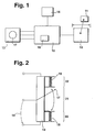
- FIG. 1 shows an embodiment of a device according to the invention and FIG. 2 a Design of the potentiometer according to the invention.
- An adjustment drive 10 moves a part 11.
- a Control electronics 12 include a closing force limitation 16 and processes signals of a position detection 14 and a potentiometer that can be actuated via an operating element 17 13. According to the potentiometer setting, the Control electronics 12 the adjustment drive 10 switching signals Available.
- Figure 2 encloses a second setting range 22 a first setting range 21. A selection of the second Adjustment range 22 takes place against the control element 17 a force applied by a spring 18. Depending on the position of the control element 17 changes a voltage 19 of the potentiometer 13.
- the control element 17 provides at least two adjustment ranges 21, 22 of the potentiometer 13 adjustable.
- the adjustment drive 10 is, for example, in the Jog mode controlled. Especially with window regulators or Sunroofs it is useful to do a typing operation without Closing force limit 16 to realize. This allows for the commissioning of the adjustment drive 10 standardization runs to be carried out on the basis of the measured values of a Standardization run limit values for the closing force limit 16 to specify or the position of the actuator normalize. Only then is the first one selected Setting range 21 taking into account the Closing force limit 16 possible.
- the control element 17 can be in the first setting range 21 continuous or Specify discrete values.
- the voltage 19 changes corresponding. This voltage 19 are target positions of the Part 11 assigned. Under consideration of Actual position values, which position detection 14 determines, the target-actual difference is corrected to zero.
- the first setting range 21 it is conceivable that different slopes of the potentiometer characteristic are implemented by appropriate wiring. Thereby can be adapted to different Carry out load profiles.
- first and second Setting range 21, 22 can be recognized. Basically this is via a switch which can be actuated by the control element 17 possible. It is particularly useful, however Range limit by comparing the voltage 19 with one for the setting range limit characteristic reference voltage to investigate. If this is in accordance with the execution of the Potentiometers 13 specified reference voltage over or undershot, the control electronics 12 recognizes that a selection of the first or the second adjustment range 21, 22 is done. Here are only three feed lines to the Potentiometer 13 required. It is from one Supply voltage fed, the voltage 19 supplies Measure of the position of the control element 17.
- the end positions are particularly suitable for the second Setting range 22 on. With a rotary knob with two end positions these could be used to move the actuator in to use one way and the other. To one Bring about a change in direction of the adjustment drive 10, without an operating mode that corresponds to the first setting range 21st assigned to trigger, positions the Control electronics 12 only when the control element 17 for a specified time interval remains in its position. The the same problem also arises with one Sliding potentiometer.
- Another embodiment of the device according to the invention is characterized in that a preselection of the second Setting range 22 only against overcoming a force of the spring 18 is applied takes place. This will turn on easily implemented a push button function. Will that Operating element 17 released, the spring 18 presses it back into the first setting area 21. Especially at the Operation of a sunroof is the first setting range 21 the normal operating mode there. Should only be used in exceptional situations the first setting range 21 can be left, for example if the closing force limit 16 is to be bypassed. There however, if security is endangered, it is necessary the actuation of the control element 17 against the spring force Increased attention.
- the inventive device for Actuation of an electrical arranged in a vehicle Actuator is preferred for Window lifters or sunroofs.
Landscapes
- Engineering & Computer Science (AREA)
- Human Computer Interaction (AREA)
- Manufacturing & Machinery (AREA)
- Physics & Mathematics (AREA)
- General Physics & Mathematics (AREA)
- Automation & Control Theory (AREA)
- Mechanical Engineering (AREA)
- Power-Operated Mechanisms For Wings (AREA)
- Axle Suspensions And Sidecars For Cycles (AREA)
Claims (8)
- Dispositif servant à actionner un mécanisme de réglage (10), disposé dans un véhicule, comprenant :caractérisé en ce quiun potentiomètre (13) qui peut être actionné manuellement par un élément de manoeuvre (17), et qui prédéfinit une position d'une pièce (11) qui est mue par le mécanisme de réglage (10) et qui est réparti en au moins deux zones de réglage (21, 22),un circuit électronique de commande (13)qui commande le mécanisme de réglage (10) en fonction des zones de réglage (21, 22) du potentiomètre (13), et des positions prédéfinies,on peut régler au moins dans une première position de réglage (21) du potentiomètre (13) une position de la pièce mobile (11) de façon continue ou discrète eton peut associer au moins à une deuxième zone de réglage (22) du potentiomètre (13) une fonction de branchement.
- Dispositif selon la revendication 1,
caractérisé en ce que
on identifie au moins l'une des zones de réglage (21, 22) en comparant avec une tension (19). - Dispositif selon la revendication 1, ou 2,
caractérisé en ce que
la première zone de réglage (21) comprend la totalité de la zone de réglage et la deuxième zone de réglage (22) est formée par au moins une butée terminale. - Dispositif selon l'une des revendications 1 à 3,
caractérisé en ce que
une présélection de la deuxième zone de réglage (22) a lieu en surmontant la force d'un ressort. - Dispositif selon l'une des revendications 1 à 4,
caractérisé en ce que
l'élément de manoeuvre (17) est réalisé sous la forme d'un bouton tournant. - Dispositif selon l'une des revendications 1 à 4,
caractérisé en ce que
l'élément de manoeuvre (17) est réalisé sous la forme d'un levier qu'on pousse. - Dispositif selon l'une des revendications 1 à 6,
caractérisé par
son utilisation dans le,cas d'un toit coulissant. - Dispositif selon l'une des revendications 1 à 6,
caractérisé par
son utilisation dans le cas d'un lève-glace.
Applications Claiming Priority (2)
| Application Number | Priority Date | Filing Date | Title |
|---|---|---|---|
| DE19620106A DE19620106C1 (de) | 1996-05-18 | 1996-05-18 | Vorrichtung zum Betätigen eines in einem Fahrzeug angeordneten Verstellantriebs |
| DE19620106 | 1996-05-18 |
Publications (2)
| Publication Number | Publication Date |
|---|---|
| EP0807545A1 EP0807545A1 (fr) | 1997-11-19 |
| EP0807545B1 true EP0807545B1 (fr) | 2000-06-07 |
Family
ID=7794693
Family Applications (1)
| Application Number | Title | Priority Date | Filing Date |
|---|---|---|---|
| EP97104996A Expired - Lifetime EP0807545B1 (fr) | 1996-05-18 | 1997-03-25 | Commande pour dispositif d'actionnement pour véhicule |
Country Status (3)
| Country | Link |
|---|---|
| EP (1) | EP0807545B1 (fr) |
| DE (2) | DE19620106C1 (fr) |
| ES (1) | ES2148866T3 (fr) |
Families Citing this family (6)
| Publication number | Priority date | Publication date | Assignee | Title |
|---|---|---|---|---|
| DE19747326C2 (de) * | 1997-10-27 | 2003-08-28 | Bosch Gmbh Robert | Kraftfahrzeug-Faltdachsystem sowie Verfahren zum Betreiben eines Kraftfahrzeug-Faltdachsystems |
| DE19756041B4 (de) * | 1997-12-17 | 2007-06-21 | Robert Bosch Gmbh | Schaltungsanordnung zur Ansteuerung eines Schiebe-Hebe-Dachs eines Kraftfahrzeugs |
| DE10134813B4 (de) * | 2000-07-20 | 2004-09-23 | Küster Automotive Door Systems GmbH | Steuerung mit einer Steuereinrichtung zum Steuern/Regeln wenigstens des Stellweges eines fremdkraftbetätigten Stellantriebes eines Kraftfahrzeuges, insbesondere zum Verstellen eines Fensterhebers oder Schiebedachs |
| DE10347318B4 (de) * | 2003-10-08 | 2007-11-08 | Faurecia Innenraum Systeme Gmbh | Vorrichtung zur Feinpositionierung von verstellbaren Öffnungen in Kraftfahrzeugen |
| EP2296077B1 (fr) | 2009-09-04 | 2017-12-13 | Pepperl + Fuchs GmbH | Procédé de réglage de paramètres de fonctionnement d'un capteur et capteur pour une grandeur de mesure physique |
| CN102494601B (zh) * | 2011-12-09 | 2013-10-02 | 中国钓具技术标准化(北仑海伯)研究中心 | 一种使用电位器测量家用电动窗位移的方法 |
Citations (1)
| Publication number | Priority date | Publication date | Assignee | Title |
|---|---|---|---|---|
| DE3324107A1 (de) * | 1982-09-22 | 1984-03-22 | Webasto-Werk W. Baier GmbH & Co, 8035 Gauting | Betaetigungseinricht. fuer bewegbare teile, insbesondere fuer schiebedaecher und schiebe-hebedaecher |
Family Cites Families (2)
| Publication number | Priority date | Publication date | Assignee | Title |
|---|---|---|---|---|
| DE3829405A1 (de) * | 1988-08-30 | 1990-03-08 | Webasto Ag Fahrzeugtechnik | Betaetigungseinrichtung fuer elektromotorisch bewegbare teile von kraftfahrzeugen |
| NL9002198A (nl) * | 1990-10-10 | 1992-05-06 | Vermeulen Hollandia Octrooien | Inrichting voor het bedienen van het dakpaneel van een schuifdak of een schuif/hefdak van een motorvoertuig. |
-
1996
- 1996-05-18 DE DE19620106A patent/DE19620106C1/de not_active Expired - Fee Related
-
1997
- 1997-03-25 DE DE59701834T patent/DE59701834D1/de not_active Expired - Lifetime
- 1997-03-25 EP EP97104996A patent/EP0807545B1/fr not_active Expired - Lifetime
- 1997-03-25 ES ES97104996T patent/ES2148866T3/es not_active Expired - Lifetime
Patent Citations (1)
| Publication number | Priority date | Publication date | Assignee | Title |
|---|---|---|---|---|
| DE3324107A1 (de) * | 1982-09-22 | 1984-03-22 | Webasto-Werk W. Baier GmbH & Co, 8035 Gauting | Betaetigungseinricht. fuer bewegbare teile, insbesondere fuer schiebedaecher und schiebe-hebedaecher |
Also Published As
| Publication number | Publication date |
|---|---|
| EP0807545A1 (fr) | 1997-11-19 |
| DE19620106C1 (de) | 1997-11-20 |
| DE59701834D1 (de) | 2000-07-13 |
| ES2148866T3 (es) | 2000-10-16 |
Similar Documents
| Publication | Publication Date | Title |
|---|---|---|
| DE3348489C2 (de) | Betätigungseinrichtung für Schiebe-Hebedächer in Kraftfahrzeugen | |
| EP1371802A2 (fr) | Serrure de porte pour véhicule automobile avec condamnation centrale actionnée électromécaniquement | |
| EP1982812B2 (fr) | Commande pour camion-bétonnière | |
| EP0807545B1 (fr) | Commande pour dispositif d'actionnement pour véhicule | |
| DE1456457A1 (de) | Druckknopfsteuerung fuer Hebezeuge | |
| EP0590227B1 (fr) | Détection de blocage pour moteurs à courant continu | |
| EP0608771A1 (fr) | Dispositif et méthode d'actionnement de composants intégrés dans un véhicule automobile | |
| DE3728008A1 (de) | Betaetigungseinrichtung fuer bewegbare teile zum wahlweisen schliessen und freigeben von oeffnungen, insbesondere von schiebe-hebedaechern von kraftfahrzeugen | |
| DE29621794U1 (de) | Verstellvorrichtung insbesondere für ein Schiebe-Hebe-Dach eines Kraftfahrzeugs | |
| WO2005036293A1 (fr) | Dispositif de positionnement fin d'elements d'ouvertures deplacables dans des vehicules automobiles | |
| EP1425770B1 (fr) | Dispositif de réglage et de commande pour appareils électriques | |
| EP0257538B1 (fr) | Arrangement des interrupteurs dans des véhicules à moteur | |
| DE10232280A1 (de) | Kraftfahrzeug-Türverschluß mit einem elektromechanischen Zentralverriegelungsantrieb | |
| DE102004005705A1 (de) | Rückenlehne für einen Fahrzeugsitz und Fahrzeugsitz | |
| EP0980084B1 (fr) | Ensemble de commutateurs électriques | |
| DE10151184A1 (de) | Verfahren zur Überwachung des Reversiervorgangs von elektrisch betätigbaren Aggregaten | |
| DE102018206935B4 (de) | Steuereinrichtung und Verfahren zur Steuerung eines Fensterhebers mit Einklemmschutz für ein Kraftfahrzeug sowie eine Software zur Durchführung des Verfahrens | |
| EP3507436A1 (fr) | Système de poignée de porte pour véhicule automobile | |
| DE102017006469B3 (de) | Bedienvorrichtung zum Verstellen eines Kraftfahrzeugbauteils und Kraftfahrzeug | |
| EP1128516B2 (fr) | Procédé pour produire un signal d'obstruction et détecteur d'obstacle | |
| DE10036394B4 (de) | Bedieneinrichtung für ein elektrisch betriebenes Schiebedach eines Kraftfahrzeuges | |
| DE102007022345A1 (de) | Helligkeitssteuerung einer Beleuchtungseinrichtung mit einem Dimmer | |
| DE4234261C2 (de) | Türverriegelungseinrichtung für Kraftfahrzeuge | |
| EP0478884A1 (fr) | Dispositif de réglage de charge | |
| DE19644920B4 (de) | Einrichtung zur Erkennung der Position eines Stellelementes eines Stellgliedes |
Legal Events
| Date | Code | Title | Description |
|---|---|---|---|
| PUAI | Public reference made under article 153(3) epc to a published international application that has entered the european phase |
Free format text: ORIGINAL CODE: 0009012 |
|
| AK | Designated contracting states |
Kind code of ref document: A1 Designated state(s): DE ES FR GB IT |
|
| 17P | Request for examination filed |
Effective date: 19980519 |
|
| GRAG | Despatch of communication of intention to grant |
Free format text: ORIGINAL CODE: EPIDOS AGRA |
|
| 17Q | First examination report despatched |
Effective date: 19990825 |
|
| GRAG | Despatch of communication of intention to grant |
Free format text: ORIGINAL CODE: EPIDOS AGRA |
|
| GRAH | Despatch of communication of intention to grant a patent |
Free format text: ORIGINAL CODE: EPIDOS IGRA |
|
| GRAH | Despatch of communication of intention to grant a patent |
Free format text: ORIGINAL CODE: EPIDOS IGRA |
|
| GRAA | (expected) grant |
Free format text: ORIGINAL CODE: 0009210 |
|
| AK | Designated contracting states |
Kind code of ref document: B1 Designated state(s): DE ES FR GB IT |
|
| REF | Corresponds to: |
Ref document number: 59701834 Country of ref document: DE Date of ref document: 20000713 |
|
| ITF | It: translation for a ep patent filed | ||
| GBT | Gb: translation of ep patent filed (gb section 77(6)(a)/1977) |
Effective date: 20000816 |
|
| ET | Fr: translation filed | ||
| REG | Reference to a national code |
Ref country code: ES Ref legal event code: FG2A Ref document number: 2148866 Country of ref document: ES Kind code of ref document: T3 |
|
| PLBE | No opposition filed within time limit |
Free format text: ORIGINAL CODE: 0009261 |
|
| STAA | Information on the status of an ep patent application or granted ep patent |
Free format text: STATUS: NO OPPOSITION FILED WITHIN TIME LIMIT |
|
| 26N | No opposition filed | ||
| REG | Reference to a national code |
Ref country code: GB Ref legal event code: IF02 |
|
| PGFP | Annual fee paid to national office [announced via postgrant information from national office to epo] |
Ref country code: DE Payment date: 20150521 Year of fee payment: 19 |
|
| REG | Reference to a national code |
Ref country code: FR Ref legal event code: PLFP Year of fee payment: 20 |
|
| PGFP | Annual fee paid to national office [announced via postgrant information from national office to epo] |
Ref country code: ES Payment date: 20160322 Year of fee payment: 20 |
|
| PGFP | Annual fee paid to national office [announced via postgrant information from national office to epo] |
Ref country code: GB Payment date: 20160322 Year of fee payment: 20 Ref country code: FR Payment date: 20160322 Year of fee payment: 20 |
|
| PGFP | Annual fee paid to national office [announced via postgrant information from national office to epo] |
Ref country code: IT Payment date: 20160318 Year of fee payment: 20 |
|
| REG | Reference to a national code |
Ref country code: DE Ref legal event code: R119 Ref document number: 59701834 Country of ref document: DE |
|
| PG25 | Lapsed in a contracting state [announced via postgrant information from national office to epo] |
Ref country code: DE Free format text: LAPSE BECAUSE OF NON-PAYMENT OF DUE FEES Effective date: 20161001 |
|
| REG | Reference to a national code |
Ref country code: GB Ref legal event code: PE20 Expiry date: 20170324 |
|
| PG25 | Lapsed in a contracting state [announced via postgrant information from national office to epo] |
Ref country code: GB Free format text: LAPSE BECAUSE OF EXPIRATION OF PROTECTION Effective date: 20170324 |
|
| REG | Reference to a national code |
Ref country code: ES Ref legal event code: FD2A Effective date: 20170630 |
|
| PG25 | Lapsed in a contracting state [announced via postgrant information from national office to epo] |
Ref country code: ES Free format text: LAPSE BECAUSE OF EXPIRATION OF PROTECTION Effective date: 20170326 |