EP0807758A1 - A starter motor for internal combustion engines, in particular for motor vehicles - Google Patents
A starter motor for internal combustion engines, in particular for motor vehicles Download PDFInfo
- Publication number
- EP0807758A1 EP0807758A1 EP97107131A EP97107131A EP0807758A1 EP 0807758 A1 EP0807758 A1 EP 0807758A1 EP 97107131 A EP97107131 A EP 97107131A EP 97107131 A EP97107131 A EP 97107131A EP 0807758 A1 EP0807758 A1 EP 0807758A1
- Authority
- EP
- European Patent Office
- Prior art keywords
- pinion
- coupling
- rotor
- coupling portion
- free wheel
- Prior art date
- Legal status (The legal status is an assumption and is not a legal conclusion. Google has not performed a legal analysis and makes no representation as to the accuracy of the status listed.)
- Withdrawn
Links
- 239000007858 starting material Substances 0.000 title claims abstract description 23
- 238000002485 combustion reaction Methods 0.000 title claims abstract description 12
- 230000008878 coupling Effects 0.000 claims abstract description 51
- 238000010168 coupling process Methods 0.000 claims abstract description 51
- 238000005859 coupling reaction Methods 0.000 claims abstract description 51
- 230000000295 complement effect Effects 0.000 claims 1
- 238000004804 winding Methods 0.000 description 3
- 230000005540 biological transmission Effects 0.000 description 1
- 238000010276 construction Methods 0.000 description 1
- 230000000717 retained effect Effects 0.000 description 1
Images
Classifications
-
- F—MECHANICAL ENGINEERING; LIGHTING; HEATING; WEAPONS; BLASTING
- F02—COMBUSTION ENGINES; HOT-GAS OR COMBUSTION-PRODUCT ENGINE PLANTS
- F02N—STARTING OF COMBUSTION ENGINES; STARTING AIDS FOR SUCH ENGINES, NOT OTHERWISE PROVIDED FOR
- F02N15/00—Other power-operated starting apparatus; Component parts, details, or accessories, not provided for in, or of interest apart from groups F02N5/00 - F02N13/00
- F02N15/02—Gearing between starting-engines and started engines; Engagement or disengagement thereof
- F02N15/04—Gearing between starting-engines and started engines; Engagement or disengagement thereof the gearing including disengaging toothed gears
- F02N15/06—Gearing between starting-engines and started engines; Engagement or disengagement thereof the gearing including disengaging toothed gears the toothed gears being moved by axial displacement
-
- F—MECHANICAL ENGINEERING; LIGHTING; HEATING; WEAPONS; BLASTING
- F02—COMBUSTION ENGINES; HOT-GAS OR COMBUSTION-PRODUCT ENGINE PLANTS
- F02N—STARTING OF COMBUSTION ENGINES; STARTING AIDS FOR SUCH ENGINES, NOT OTHERWISE PROVIDED FOR
- F02N15/00—Other power-operated starting apparatus; Component parts, details, or accessories, not provided for in, or of interest apart from groups F02N5/00 - F02N13/00
- F02N15/02—Gearing between starting-engines and started engines; Engagement or disengagement thereof
- F02N15/022—Gearing between starting-engines and started engines; Engagement or disengagement thereof the starter comprising an intermediate clutch
- F02N15/023—Gearing between starting-engines and started engines; Engagement or disengagement thereof the starter comprising an intermediate clutch of the overrunning type
Definitions
- the present invention relates to a starter motor for an internal combustion engine, in particular for motor vehicles. More particularly, the present invention relates to a starter motor comprising a shaft separated into two portions and a pinion stop device for limiting the movement of the pinion upon engaging with a gear ring on the flywheel of the internal combustion engine.
- the pinion is slidable on the starter motor shaft in such a way as to be able to mesh with the gear ring during starting. Stop means for limiting the path of the pinion are therefore necessary.
- a stop ring which is fixed to one end of the shaft by means of a circlip fitted in a groove formed on the shaft itself, or by two collets which are coupled on a circlip also fixed in a groove provided at one end of the shaft.
- the object of the present invention is that of providing a starter motor for an internal combustion engine which allows all the above-indicated problems to be resolved in a satisfactory manner and which is easy to assemble and has a high reliability.
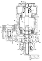
- A indicates a starter motor shaft.
- the shaft A is subdivided into two portions, indicated 2 and 4, corresponding respectively to a coupling shaft 2 and a rotor shaft 4.
- the coupling shaft 2 supports a pinion 10 intended, as mentioned above, to mesh with a gear ring 42 provided on a flywheel of an internal combustion engine;
- the rotor shaft 4 on the other hand supports a rotor comprising a plurality of rotor windings 32 of the starter motor.
- the coupling shaft 2 and the rotor shaft 4 are connected together by corresponding form-fitting shaped end 6 provided at their respective facing ends, which guarantee the transmission of torque from the rotor shaft 4 to the coupling shaft 2 and further serve as supports for the rotor shaft 4.
- the rotor shaft 4 is in fact supported at one end, the end opposite the coupling shaft 2, by a support 14 positioned close to a commutator C operable to supply the rotor windings 32, whilst at the end facing the coupling shaft 2 it is supported by the coupling at the shaped end 6 of the coupling shaft 2 itself.
- the support 14 at the commutator end of the shaft is applied to a casing 30 of the starter motor carrying an inductor winding and containing the rotor 32.
- the coupling formed by the shaped end 6 also allows alignment of the coupling shaft 2 and the rotor shaft 4 with one another and with respect to a support structure 8 situated in correspondence with the coupling shaft 2.
- This coupling shaft 2 is in fact supported by a support structure 8 by means of a bush or bearing 26 and an intermediate support 12 as will be better explained hereinafter.
- a splined portion 16a of the coupling shaft 2 permits a coupling unit constituted by the pinion 10 and the free wheel 18 to slide axially on it.
- the starter motor in fact includes, for the purpose of causing sliding of the coupling unit 10, 18, a lever 34 which acts on the free wheel 18 in an arrangement widely known in the art.
- the lever 34 is actuated by means of an electromagnet 38.
- the electromagnet 38 When, at the beginning of the starting operation, the electromagnet 38 is activated it presses the free wheel 18 and the pinion 10 towards the gear ring 42. In this way it causes meshing of a toothed end portion 40 of the pinion 10 with the gear ring 42. Almost simultaneously the electromagnet 38 closes a supply circuit to the starter motor which therefore causes starting of the internal combustion engine.
- the coupling unit 10, 18 is mounted in an axially slidable manner on a grooved portion 16a of the coupling shaft 2. More precisely a hub of the free wheel 18 has a correspondingly splined internal portion 16b which allows it to slide axially, but not to rotate, with respect to the coupling shaft 2.
- the hub of the free wheel 18 is connected by means of the free wheel coupling to the pinion 10 which can rotate or translate on the coupling shaft 2.
- the pinion 10 can therefore slide axially in a fixed manner with the free wheel 18 and can rotate on the coupling shaft 2.
- the rotation of the pinion 10 is however limited by the free wheel device 18 which permits the pinion 10 to rotate in the same direction but more rapidly than the hub of the free wheel 18 when it is driven to rotate by the internal combustion engine, whilst when the starter motor drives the rotation of the internal combustion engine the pinion 10 is driven to rotate fixedly by the free wheel hub 18 at the same speed of rotation as the coupling shaft 2.
- the axial sliding of the hub of the free wheel 18 on the grooved portion 16a of the coupling shaft 2 is delimited at one end of the intended path by an annular projection 20 formed on the coupling shaft 2 by means of a variation in diameter provided at one end of the grooved portion 16a, against which the end 16c of the grooved portion 16b of the free wheel hub 18 abuts.
- the path of the free wheel hub 18 is limited by the intermediate support 12.
- the intermediate support 12 On the assembly formed by the coupling shaft 2 and the coupling unit 10, 18 is mounted the intermediate support 12 which is locked in the desired position by means of a resilient stop ring or Seeger 22 with the interposition of plain or star washers 24.
- the assembly formed by the coupling unit 10, 18, the coupling shaft 2 and the intermediate support 12 is mounted and centred in the support structure 8 at the pinion end (10) by means of a bush or bearing 26 which supports the pinion 10 and, at the opposite end, by means of a centring recess 28 of substantially annular form provided with an abutment surface situated in the portion of the support structure 8 facing the rotor 32 and intended to function as a seat for the intermediate support 12.
- the assembly of the starter motor is completed by assembling the casing 30 which axially fixes the intermediate support 12 and by inserting the rotor 32 with its shaft 4 and the support at the commutator 14 end.
- the operation of the starter motor which is the subject of the present invention is as follows.
- the electromagnet 38 thrusts the free wheel 18 towards the ring gear 42 by means of the lever 34.
- the free wheel 18, urged by the lever 34 continues along its path towards the ring gear 42 until the toothed portion 40 of the pinion 10 is introduced between the teeth of the ring gear 42 of the internal combustion engine's flywheel.
- the axial path of the free wheel 18 is limited by the fact that the end 16c of the grooved portion 16b of the hub of the free wheel 18 facing towards the ring gear 42 comes up against the stop ring 20 of the coupling shaft 2.
- the electromagnet 38 also simultaneously supplies the starter motor the rotor 32 of which starts to turn and, with its rotor shaft 4 drives the coupling shaft 2 to rotate by means of the coupling of the shaped end 6.
- the coupling shaft 2 retained in axial position by the intermediate support 12 by means of the Seeger 22 and the washers 24 drives the free wheel 18, and therefore also the pinion 10, to rotate by means of the splined coupling 16a.
Landscapes
- Engineering & Computer Science (AREA)
- Chemical & Material Sciences (AREA)
- Combustion & Propulsion (AREA)
- Mechanical Engineering (AREA)
- General Engineering & Computer Science (AREA)
- Output Control And Ontrol Of Special Type Engine (AREA)
- Valve Device For Special Equipments (AREA)
- Connection Of Motors, Electrical Generators, Mechanical Devices, And The Like (AREA)
Applications Claiming Priority (2)
| Application Number | Priority Date | Filing Date | Title |
|---|---|---|---|
| ITTO960363 | 1996-05-06 | ||
| IT96TO000363A IT1285858B1 (it) | 1996-05-06 | 1996-05-06 | Motore di avviamento per motori a combustione interna, in particolare per autoveicoli. |
Publications (1)
| Publication Number | Publication Date |
|---|---|
| EP0807758A1 true EP0807758A1 (en) | 1997-11-19 |
Family
ID=11414606
Family Applications (1)
| Application Number | Title | Priority Date | Filing Date |
|---|---|---|---|
| EP97107131A Withdrawn EP0807758A1 (en) | 1996-05-06 | 1997-04-30 | A starter motor for internal combustion engines, in particular for motor vehicles |
Country Status (3)
| Country | Link |
|---|---|
| EP (1) | EP0807758A1 (it) |
| BR (1) | BR9700662A (it) |
| IT (1) | IT1285858B1 (it) |
Citations (3)
| Publication number | Priority date | Publication date | Assignee | Title |
|---|---|---|---|---|
| US4295069A (en) * | 1978-04-17 | 1981-10-13 | General Motors Corporation | Armature shaft for a vehicle starter motor |
| US4347442A (en) * | 1980-07-14 | 1982-08-31 | Eaton Stamping Company | Double insulated starter motor |
| JPH02224843A (ja) * | 1989-02-28 | 1990-09-06 | Mitsubishi Electric Corp | 出力回転軸の製造方法 |
-
1996
- 1996-05-06 IT IT96TO000363A patent/IT1285858B1/it active IP Right Grant
-
1997
- 1997-04-30 EP EP97107131A patent/EP0807758A1/en not_active Withdrawn
- 1997-05-05 BR BR9700662A patent/BR9700662A/pt not_active IP Right Cessation
Patent Citations (3)
| Publication number | Priority date | Publication date | Assignee | Title |
|---|---|---|---|---|
| US4295069A (en) * | 1978-04-17 | 1981-10-13 | General Motors Corporation | Armature shaft for a vehicle starter motor |
| US4347442A (en) * | 1980-07-14 | 1982-08-31 | Eaton Stamping Company | Double insulated starter motor |
| JPH02224843A (ja) * | 1989-02-28 | 1990-09-06 | Mitsubishi Electric Corp | 出力回転軸の製造方法 |
Non-Patent Citations (1)
| Title |
|---|
| PATENT ABSTRACTS OF JAPAN vol. 014, no. 532 (M - 1051) 22 November 1990 (1990-11-22) * |
Also Published As
| Publication number | Publication date |
|---|---|
| BR9700662A (pt) | 1998-11-03 |
| ITTO960363A0 (it) | 1996-05-06 |
| ITTO960363A1 (it) | 1997-11-06 |
| IT1285858B1 (it) | 1998-06-24 |
Similar Documents
| Publication | Publication Date | Title |
|---|---|---|
| US7353895B2 (en) | Vehicle transmission with selectively-engageable electric motor | |
| EP0276315B1 (en) | Planetary gear type reduction starter | |
| EP0913601B1 (de) | Anbindung für einen Drehmomentwandler | |
| US7219569B2 (en) | Integral one-way overrun clutch with epcicycle gear system | |
| US4932273A (en) | Starter for an internal combustion engine | |
| JPH11241669A (ja) | 改良型オーバーランクラッチを組み込んだ自動車エンジン用スタータ | |
| KR920006243B1 (ko) | 스타터 장치 | |
| US4304140A (en) | Starter | |
| US6041901A (en) | Torque transmitter connection assembly with vibration damper and method of making same | |
| US5052235A (en) | Spaced bearing arrangement for coaxial engine starter | |
| US20090151684A1 (en) | Starter arrangement for an internal combustion engine | |
| KR950009975B1 (ko) | 시동장치 | |
| US3140617A (en) | Engine starting apparatus | |
| US7370619B2 (en) | Starter system for internal combustion engine | |
| KR940010656B1 (ko) | 동축형 시동기 장치 | |
| EP0807758A1 (en) | A starter motor for internal combustion engines, in particular for motor vehicles | |
| US6647812B2 (en) | Starter motor having intermediate gear | |
| KR940010654B1 (ko) | 동축형 스타터장치 | |
| US5540110A (en) | Starter motor pinion stopper placement | |
| EP3555456B1 (en) | A drive system for an engine arrangement | |
| US6006618A (en) | Starter motor with rear bracket elements fixed by through-bolts | |
| US7938243B2 (en) | Thrust washer to take torque converter axial loading | |
| US4092870A (en) | Engine starting mechanism | |
| EP3910208B1 (en) | All-terrain vehicle and starting protector for all-terrain vehicle | |
| US6774529B1 (en) | Rotor body |
Legal Events
| Date | Code | Title | Description |
|---|---|---|---|
| PUAI | Public reference made under article 153(3) epc to a published international application that has entered the european phase |
Free format text: ORIGINAL CODE: 0009012 |
|
| AK | Designated contracting states |
Kind code of ref document: A1 Designated state(s): DE ES FR GB SE |
|
| 17P | Request for examination filed |
Effective date: 19980509 |
|
| RAP1 | Party data changed (applicant data changed or rights of an application transferred) |
Owner name: DENSO MANUFACTURING ITALIA S.P.A. |
|
| 17Q | First examination report despatched |
Effective date: 20000727 |
|
| STAA | Information on the status of an ep patent application or granted ep patent |
Free format text: STATUS: THE APPLICATION IS DEEMED TO BE WITHDRAWN |
|
| 18D | Application deemed to be withdrawn |
Effective date: 20001207 |