EP0807787A2 - Brûleur - Google Patents
Brûleur Download PDFInfo
- Publication number
- EP0807787A2 EP0807787A2 EP97810221A EP97810221A EP0807787A2 EP 0807787 A2 EP0807787 A2 EP 0807787A2 EP 97810221 A EP97810221 A EP 97810221A EP 97810221 A EP97810221 A EP 97810221A EP 0807787 A2 EP0807787 A2 EP 0807787A2
- Authority
- EP
- European Patent Office
- Prior art keywords
- burner
- fuel
- air inlet
- plane
- overlap
- Prior art date
- Legal status (The legal status is an assumption and is not a legal conclusion. Google has not performed a legal analysis and makes no representation as to the accuracy of the status listed.)
- Granted
Links
Images
Classifications
-
- F—MECHANICAL ENGINEERING; LIGHTING; HEATING; WEAPONS; BLASTING
- F23—COMBUSTION APPARATUS; COMBUSTION PROCESSES
- F23D—BURNERS
- F23D17/00—Burners for combustion simultaneously or alternately of gaseous or liquid or pulverulent fuel
- F23D17/002—Burners for combustion simultaneously or alternately of gaseous or liquid or pulverulent fuel gaseous or liquid fuel
-
- F—MECHANICAL ENGINEERING; LIGHTING; HEATING; WEAPONS; BLASTING
- F23—COMBUSTION APPARATUS; COMBUSTION PROCESSES
- F23C—METHODS OR APPARATUS FOR COMBUSTION USING FLUID FUEL OR SOLID FUEL SUSPENDED IN A CARRIER GAS OR AIR
- F23C7/00—Combustion apparatus characterised by arrangements for air supply
- F23C7/002—Combustion apparatus characterised by arrangements for air supply the air being submitted to a rotary or spinning motion
-
- F—MECHANICAL ENGINEERING; LIGHTING; HEATING; WEAPONS; BLASTING
- F23—COMBUSTION APPARATUS; COMBUSTION PROCESSES
- F23C—METHODS OR APPARATUS FOR COMBUSTION USING FLUID FUEL OR SOLID FUEL SUSPENDED IN A CARRIER GAS OR AIR
- F23C2900/00—Special features of, or arrangements for combustion apparatus using fluid fuels or solid fuels suspended in air; Combustion processes therefor
- F23C2900/07002—Premix burners with air inlet slots obtained between offset curved wall surfaces, e.g. double cone burners
Definitions
- the invention relates to the field of combustion technology. It relates to a burner of the double-cone type, in which gaseous fuel is supplied to the combustion air flow before it flows into the interior of the burner.
- EP 0 321 809 B1 discloses the basic structure of a double-cone type burner to which the invention relates.
- This burner consists essentially of hollow, part-cone bodies that complement one another, with tangential air inlet slots and feeds for gaseous and liquid fuels, in which the central axes of the hollow part-cone bodies have a conical inclination widening in the flow direction and are offset in the longitudinal direction.
- a fuel nozzle is placed on the burner head.
- the gaseous fuel is supplied to the combustion air stream in advance of its inflow into the interior of the burner via gas injectors arranged along the inlet slots.
- the fuel / air mixture is thus formed directly at the end of the tangential air inlet slots.
- the air entry level and the gas entry level (Perforation level) thus coincide in this known prior art.
- the ignition of the flame is only initiated at the stagnation point of the return flow zone.
- the last gas injectors along the air inlet slots are very close to the burner outlet and thus also in the vicinity of the flame.
- the length of the pre-mixing section is therefore very short at these points, so that the fuel which is injected from these last nozzles located downstream can only mix poorly with the air.
- the poor premixing of the fuel with air creates local areas with a rich fuel / air mixture, which leads to higher flame temperatures and thus to higher NOx values.
- the additional load on the firing front in these regions becomes so high that overheating occurs and the material there has to be protected by an expensive zirconium coating.
- the invention tries to avoid all of these disadvantages. It is the object of the invention to create a burner of the double-cone type, which is simple in construction and therefore inexpensive to manufacture, and in which an improved premixing of the gaseous fuel from the downstream last gas injection nozzles with the combustion air takes place, so that compared to the known prior art NOx emissions are reduced and the burner front is subjected to less thermal stress, so that expensive special coatings on the burner front can be dispensed with.
- this is achieved in that the partial cone bodies overlap in a burner according to the preamble of claim 1, the overlap angle increasing in the flow direction of the burner and at the same time the distance of the fuel injectors from the air inlet plane into the burner increasing with an increase in the overlap angle.
- the fuel injection plane and the air inlet plane therefore no longer coincide, but the fuel injection plane changes along the burner in the position relative to the air inlet plane.
- the advantages of the invention are, inter alia, that the premixing of the gaseous fuel with the combustion air is improved in the area of the downstream fuel injectors due to the enlarged premixing section, so that the NOx emissions and the thermal load on the burner front are reduced.
- the burner is characterized by a more stable flame position and lower pulsations.
- the overlap angle in the cone tip is 0 ° and increases continuously up to the burner front, the maximum overlap angle being 90 °.
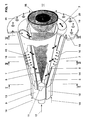
- FIG. 1 shows a perspective view of the burner according to the invention. For a better understanding, it is advantageous if the cuts in FIGS. 2 to 4 are used simultaneously with FIG. 1.
- the offset of the respective central axes 3, 4 of the partial cone bodies 1, 2 to each other creates a tangential air inlet slot 5, 6 on both sides in a mirror-image arrangement, through which the combustion air 7 enters the interior 8 of the burner.
- the two partial cone bodies 1, 2 each have a cylindrical starting part 9, 10, which likewise run offset from one another, so that the tangential air inlet slots 5, 6 are also present in this area.
- a nozzle 11 for atomizing the liquid fuel 12 is accommodated in this cylindrical starting part 9, 10.
- the burner can also be designed without the cylindrical starting parts 9, 10, so that it is designed to be purely conical. Then the fuel nozzle 11 is accommodated directly in the cone tip.
- the two partial cone bodies 1, 2 each have a fuel line 13, 14 which are provided with openings 15 which represent fuel injectors.
- the fuel injectors 15 add gaseous fuel 16 to the combustion air 7 flowing through the tangential air inlet slots 5,
- the burner has a front plate 18 serving as anchoring for the partial cone bodies 1, 2 with a number of bores 19 through which, if necessary, dilution or cooling air 20 can be supplied to the front part of the combustion chamber 17 or its wall.
- liquid fuel 12 If liquid fuel 12 is used to operate the burner, it flows through the nozzle 11 and is injected into the burner interior 17 at an acute angle, a homogeneous fuel spray being produced.
- the tapered liquid fuel profile 23 is of a tangentially flowing rotating combustion air flow 7 enclosed. In the axial direction, the concentration of the liquid fuel 12 is continuously reduced by the mixed-in combustion air 7.
- the optimum fuel concentration across the cross section is only achieved in the area of the vortex burst, ie in the area of the backflow zone 24.
- the ignition takes place at the tip of the backflow zone 24. Only at this point does a stable flame front 25 arise.
- the flame stabilization results from an increase in the number of swirls in the direction of flow along the cone axis. The flame does not kick back inside the burner.
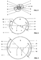
- the two partial cone bodies 1, 2 partially overlap, the overlap angle ⁇ in the cone tip being 0 ° (ie there is no overlap) and ⁇ then increases continuously in the direction of flow up to the burner outlet, that is to say to the front plate 18. 90 ° can be specified as the maximum overlap angle ⁇ .
- the air flow 7 is channeled through the overlapped walls of the partial cone bodies 1, 2.
- the fuel injectors 15 are offset further upstream.
- the air inlet level 21 and the fuel injection level thus fall 22 no longer together.
- the fuel injection plane 22 changes its position along the double-cone burner in the direction of the burner front in relation to the air inlet plane 21 such that ever larger premixing distances are reached from the respective fuel injection of the gaseous fuel 16 to the air inlet plane 21.
- the flame has a more stable position compared to the previously known prior art, in which the partial cone bodies 1, 2 do not overlap and the fuel injection plane 22 corresponds to the air inlet plane 21.
- the burner according to the invention also has less tendency to pulsate. It is structurally fairly simple (e.g. without complicated transition pieces to extend the pre-mixing section) and is therefore inexpensive to manufacture.
- the invention is not limited to the embodiment just described.
- the solution according to the invention can also be used for burners which consist of more than two partial cone bodies, for example for so-called four-slot burners.
Landscapes
- Engineering & Computer Science (AREA)
- Chemical & Material Sciences (AREA)
- Combustion & Propulsion (AREA)
- Mechanical Engineering (AREA)
- General Engineering & Computer Science (AREA)
- Gas Burners (AREA)
Applications Claiming Priority (2)
| Application Number | Priority Date | Filing Date | Title |
|---|---|---|---|
| DE19619873A DE19619873A1 (de) | 1996-05-17 | 1996-05-17 | Brenner |
| DE19619873 | 1996-05-17 |
Publications (3)
| Publication Number | Publication Date |
|---|---|
| EP0807787A2 true EP0807787A2 (fr) | 1997-11-19 |
| EP0807787A3 EP0807787A3 (fr) | 1999-03-24 |
| EP0807787B1 EP0807787B1 (fr) | 2003-05-28 |
Family
ID=7794546
Family Applications (1)
| Application Number | Title | Priority Date | Filing Date |
|---|---|---|---|
| EP97810221A Expired - Lifetime EP0807787B1 (fr) | 1996-05-17 | 1997-04-14 | Brûleur |
Country Status (5)
| Country | Link |
|---|---|
| US (1) | US5921766A (fr) |
| EP (1) | EP0807787B1 (fr) |
| JP (1) | JP3863631B2 (fr) |
| CN (1) | CN1117243C (fr) |
| DE (2) | DE19619873A1 (fr) |
Cited By (3)
| Publication number | Priority date | Publication date | Assignee | Title |
|---|---|---|---|---|
| EP0918191A1 (fr) * | 1997-11-21 | 1999-05-26 | Abb Research Ltd. | Brûleur pour la mise en oeuvre d'un générateur de chaleur |
| EP0959298A3 (fr) * | 1998-05-18 | 2000-02-23 | United Technologies Corporation | Injecteur de combustible à prémélange et son procédé de mise en oeuvre |
| US8516825B2 (en) | 2003-07-24 | 2013-08-27 | Alstom Technology Ltd | Method for reducing the NOx emissions from a burner arrangement comprising a plurality of burners, and burner arrangement for carrying out the method |
Families Citing this family (6)
| Publication number | Priority date | Publication date | Assignee | Title |
|---|---|---|---|---|
| EP1262714A1 (fr) * | 2001-06-01 | 2002-12-04 | ALSTOM (Switzerland) Ltd | Brûleur avec recirculation des gaz de combustion |
| US7097448B2 (en) * | 2004-05-07 | 2006-08-29 | Peter Chesney | Vortex type gas lamp |
| USD621873S1 (en) | 2009-07-09 | 2010-08-17 | Science Centre Board | Fire tornado lamp |
| CA2786597A1 (fr) | 2010-01-06 | 2011-07-14 | The Outdoor Greatroom Company LLLP | Ensemble brasero |
| US10281140B2 (en) | 2014-07-15 | 2019-05-07 | Chevron U.S.A. Inc. | Low NOx combustion method and apparatus |
| US11852319B2 (en) * | 2021-02-26 | 2023-12-26 | Armando Parra | Control means for vortex flame device |
Family Cites Families (10)
| Publication number | Priority date | Publication date | Assignee | Title |
|---|---|---|---|---|
| US3570471A (en) * | 1969-02-14 | 1971-03-16 | Thermo Electron Corp | Radiant tube having uniform high-temperature distribution |
| EP0210462B1 (fr) * | 1985-07-30 | 1989-03-15 | BBC Brown Boveri AG | Chambre de combustion double |
| CH674561A5 (fr) * | 1987-12-21 | 1990-06-15 | Bbc Brown Boveri & Cie | |
| EP0481111B1 (fr) * | 1990-10-17 | 1995-06-28 | Asea Brown Boveri Ag | Chambre de combustion pour turbine à gaz |
| EP0548396B1 (fr) * | 1991-12-23 | 1995-02-22 | Asea Brown Boveri Ag | Dispositif servant à mélanger deux composants gazeux et brûleur dans lequel ce dispositif est appliqué |
| US5307634A (en) * | 1992-02-26 | 1994-05-03 | United Technologies Corporation | Premix gas nozzle |
| DE4304213A1 (de) * | 1993-02-12 | 1994-08-18 | Abb Research Ltd | Brenner zum Betrieb einer Brennkraftmaschine, einer Brennkammer einer Gasturbogruppe oder Feuerungsanlage |
| DE4330083A1 (de) * | 1993-09-06 | 1995-03-09 | Abb Research Ltd | Verfahren zum Betrieb eines Vormischbrenners |
| US5461865A (en) * | 1994-02-24 | 1995-10-31 | United Technologies Corporation | Tangential entry fuel nozzle |
| DE19502796B4 (de) * | 1995-01-30 | 2004-10-28 | Alstom | Brenner |
-
1996
- 1996-05-17 DE DE19619873A patent/DE19619873A1/de not_active Withdrawn
-
1997
- 1997-04-14 EP EP97810221A patent/EP0807787B1/fr not_active Expired - Lifetime
- 1997-04-14 DE DE59710156T patent/DE59710156D1/de not_active Expired - Lifetime
- 1997-05-07 US US08/852,548 patent/US5921766A/en not_active Expired - Lifetime
- 1997-05-16 CN CN97111195A patent/CN1117243C/zh not_active Expired - Lifetime
- 1997-05-16 JP JP12659797A patent/JP3863631B2/ja not_active Expired - Lifetime
Cited By (4)
| Publication number | Priority date | Publication date | Assignee | Title |
|---|---|---|---|---|
| EP0918191A1 (fr) * | 1997-11-21 | 1999-05-26 | Abb Research Ltd. | Brûleur pour la mise en oeuvre d'un générateur de chaleur |
| US6155820A (en) * | 1997-11-21 | 2000-12-05 | Abb Research Ltd. | Burner for operating a heat generator |
| EP0959298A3 (fr) * | 1998-05-18 | 2000-02-23 | United Technologies Corporation | Injecteur de combustible à prémélange et son procédé de mise en oeuvre |
| US8516825B2 (en) | 2003-07-24 | 2013-08-27 | Alstom Technology Ltd | Method for reducing the NOx emissions from a burner arrangement comprising a plurality of burners, and burner arrangement for carrying out the method |
Also Published As
| Publication number | Publication date |
|---|---|
| JP3863631B2 (ja) | 2006-12-27 |
| US5921766A (en) | 1999-07-13 |
| CN1117243C (zh) | 2003-08-06 |
| DE59710156D1 (de) | 2003-07-03 |
| CN1172227A (zh) | 1998-02-04 |
| EP0807787A3 (fr) | 1999-03-24 |
| JPH1068511A (ja) | 1998-03-10 |
| DE19619873A1 (de) | 1997-11-20 |
| EP0807787B1 (fr) | 2003-05-28 |
Similar Documents
| Publication | Publication Date | Title |
|---|---|---|
| EP0321809B1 (fr) | Procédé pour la combustion de combustible liquide dans un brûleur | |
| EP0387532B1 (fr) | Chambre de combustion d'une turbine à gaz | |
| EP0503319B1 (fr) | Brûleur pour une combustion à mélange préalable d'un combustible liquide et/ou gazeux | |
| EP0401529B1 (fr) | Chambre de combustion d'une turbine à gaz | |
| CH680467A5 (fr) | ||
| EP0911583B1 (fr) | Procédé de mise en oeuvre d'un brûleur à prémélange | |
| DE19545310B4 (de) | Vormischbrenner | |
| DE19730617A1 (de) | Druckzerstäuberdüse | |
| CH680157A5 (fr) | ||
| EP0778445B1 (fr) | Brûleur à prémélange | |
| DE19640198A1 (de) | Vormischbrenner | |
| EP0394800B1 (fr) | Brûleur à mélange préalable pour la génération de gaz chaud | |
| EP0816759B1 (fr) | Brûleur à prémélange et procédé de mise en oeuvre du brûleur | |
| EP0433789A1 (fr) | Procédé d'une combustion à mélange préalable d'un combustible liquide | |
| EP0641971A2 (fr) | Procédé pour commander un brûleur à prémélange | |
| EP0742411B1 (fr) | Alimentation en air pour une chambre de combustion à prémélange | |
| EP0851172A2 (fr) | Brûleur pour la mise en oeuvre d'une chambre de combustion avec un combustible liquide ou gazeux | |
| EP0807787B1 (fr) | Brûleur | |
| EP0483554B1 (fr) | Procédé pour la réduction au minimum des émissions de NOx dans une combustion | |
| EP0924458B1 (fr) | Brûleur | |
| DE4412315B4 (de) | Verfahren und Vorrichtung zum Betreiben der Brennkammer einer Gasturbine | |
| DE19547914A1 (de) | Vormischbrenner für einen Wärmeerzeuger | |
| DE19721937A1 (de) | Brenner zum Betrieb eines Aggregates zur Erzeugung eines Heissgases | |
| EP0881431A2 (fr) | Brûleur pour la mise en oeuvre d'une unité pour la génération d'un gaz chaud | |
| DE19542164A1 (de) | Vormischbrenner |
Legal Events
| Date | Code | Title | Description |
|---|---|---|---|
| PUAI | Public reference made under article 153(3) epc to a published international application that has entered the european phase |
Free format text: ORIGINAL CODE: 0009012 |
|
| AK | Designated contracting states |
Kind code of ref document: A2 Designated state(s): DE FR GB IT NL SE |
|
| PUAL | Search report despatched |
Free format text: ORIGINAL CODE: 0009013 |
|
| AK | Designated contracting states |
Kind code of ref document: A3 Designated state(s): DE FR GB IT NL SE |
|
| 17P | Request for examination filed |
Effective date: 19990824 |
|
| RAP1 | Party data changed (applicant data changed or rights of an application transferred) |
Owner name: ALSTOM |
|
| GRAG | Despatch of communication of intention to grant |
Free format text: ORIGINAL CODE: EPIDOS AGRA |
|
| 17Q | First examination report despatched |
Effective date: 20020605 |
|
| RAP1 | Party data changed (applicant data changed or rights of an application transferred) |
Owner name: ALSTOM (SWITZERLAND) LTD |
|
| GRAG | Despatch of communication of intention to grant |
Free format text: ORIGINAL CODE: EPIDOS AGRA |
|
| GRAH | Despatch of communication of intention to grant a patent |
Free format text: ORIGINAL CODE: EPIDOS IGRA |
|
| GRAH | Despatch of communication of intention to grant a patent |
Free format text: ORIGINAL CODE: EPIDOS IGRA |
|
| GRAA | (expected) grant |
Free format text: ORIGINAL CODE: 0009210 |
|
| AK | Designated contracting states |
Designated state(s): DE FR GB IT NL SE |
|
| PG25 | Lapsed in a contracting state [announced via postgrant information from national office to epo] |
Ref country code: NL Free format text: LAPSE BECAUSE OF FAILURE TO SUBMIT A TRANSLATION OF THE DESCRIPTION OR TO PAY THE FEE WITHIN THE PRESCRIBED TIME-LIMIT Effective date: 20030528 |
|
| REG | Reference to a national code |
Ref country code: GB Ref legal event code: FG4D Free format text: NOT ENGLISH |
|
| REF | Corresponds to: |
Ref document number: 59710156 Country of ref document: DE Date of ref document: 20030703 Kind code of ref document: P |
|
| REG | Reference to a national code |
Ref country code: SE Ref legal event code: TRGR |
|
| GBT | Gb: translation of ep patent filed (gb section 77(6)(a)/1977) | ||
| NLV1 | Nl: lapsed or annulled due to failure to fulfill the requirements of art. 29p and 29m of the patents act | ||
| ET | Fr: translation filed | ||
| PLBE | No opposition filed within time limit |
Free format text: ORIGINAL CODE: 0009261 |
|
| STAA | Information on the status of an ep patent application or granted ep patent |
Free format text: STATUS: NO OPPOSITION FILED WITHIN TIME LIMIT |
|
| 26N | No opposition filed |
Effective date: 20040302 |
|
| REG | Reference to a national code |
Ref country code: DE Ref legal event code: R082 Ref document number: 59710156 Country of ref document: DE Representative=s name: UWE ROESLER, DE |
|
| REG | Reference to a national code |
Ref country code: GB Ref legal event code: 732E Free format text: REGISTERED BETWEEN 20120802 AND 20120808 |
|
| REG | Reference to a national code |
Ref country code: DE Ref legal event code: R082 Ref document number: 59710156 Country of ref document: DE Representative=s name: ROESLER, UWE, DIPL.-PHYS.UNIV., DE Effective date: 20120713 Ref country code: DE Ref legal event code: R081 Ref document number: 59710156 Country of ref document: DE Owner name: GENERAL ELECTRIC TECHNOLOGY GMBH, CH Free format text: FORMER OWNER: ALSTOM (SWITZERLAND) LTD., BADEN, CH Effective date: 20120713 Ref country code: DE Ref legal event code: R081 Ref document number: 59710156 Country of ref document: DE Owner name: ALSTOM TECHNOLOGY LTD., CH Free format text: FORMER OWNER: ALSTOM (SWITZERLAND) LTD., BADEN, CH Effective date: 20120713 |
|
| REG | Reference to a national code |
Ref country code: FR Ref legal event code: TP Owner name: ALSTOM TECHNOLOGY LTD., CH Effective date: 20120918 |
|
| REG | Reference to a national code |
Ref country code: FR Ref legal event code: PLFP Year of fee payment: 20 |
|
| PGFP | Annual fee paid to national office [announced via postgrant information from national office to epo] |
Ref country code: DE Payment date: 20160421 Year of fee payment: 20 Ref country code: GB Payment date: 20160421 Year of fee payment: 20 |
|
| REG | Reference to a national code |
Ref country code: DE Ref legal event code: R082 Ref document number: 59710156 Country of ref document: DE Representative=s name: ROESLER, UWE, DIPL.-PHYS.UNIV., DE Ref country code: DE Ref legal event code: R081 Ref document number: 59710156 Country of ref document: DE Owner name: GENERAL ELECTRIC TECHNOLOGY GMBH, CH Free format text: FORMER OWNER: ALSTOM TECHNOLOGY LTD., BADEN, CH |
|
| PGFP | Annual fee paid to national office [announced via postgrant information from national office to epo] |
Ref country code: IT Payment date: 20160427 Year of fee payment: 20 Ref country code: FR Payment date: 20160421 Year of fee payment: 20 Ref country code: SE Payment date: 20160420 Year of fee payment: 20 |
|
| REG | Reference to a national code |
Ref country code: FR Ref legal event code: CD Owner name: ALSTOM TECHNOLOGY LTD, CH Effective date: 20161110 |
|
| REG | Reference to a national code |
Ref country code: DE Ref legal event code: R071 Ref document number: 59710156 Country of ref document: DE |
|
| REG | Reference to a national code |
Ref country code: GB Ref legal event code: PE20 Expiry date: 20170413 |
|
| PG25 | Lapsed in a contracting state [announced via postgrant information from national office to epo] |
Ref country code: GB Free format text: LAPSE BECAUSE OF EXPIRATION OF PROTECTION Effective date: 20170413 |
|
| REG | Reference to a national code |
Ref country code: FR Ref legal event code: TP Owner name: ANSALDO ENERGIA IP UK LIMITED, GB Effective date: 20171221 |