EP0807800A1 - Koordinatendetektionssystem mit assoziertem verfahren und spielapparat - Google Patents
Koordinatendetektionssystem mit assoziertem verfahren und spielapparat Download PDFInfo
- Publication number
- EP0807800A1 EP0807800A1 EP96935345A EP96935345A EP0807800A1 EP 0807800 A1 EP0807800 A1 EP 0807800A1 EP 96935345 A EP96935345 A EP 96935345A EP 96935345 A EP96935345 A EP 96935345A EP 0807800 A1 EP0807800 A1 EP 0807800A1
- Authority
- EP
- European Patent Office
- Prior art keywords
- detecting
- coordinates
- light
- scanning
- image display
- Prior art date
- Legal status (The legal status is an assumption and is not a legal conclusion. Google has not performed a legal analysis and makes no representation as to the accuracy of the status listed.)
- Withdrawn
Links
Images



Classifications
-
- A—HUMAN NECESSITIES
- A63—SPORTS; GAMES; AMUSEMENTS
- A63F—CARD, BOARD, OR ROULETTE GAMES; INDOOR GAMES USING SMALL MOVING PLAYING BODIES; VIDEO GAMES; GAMES NOT OTHERWISE PROVIDED FOR
- A63F13/00—Video games, i.e. games using an electronically generated display having two or more dimensions
- A63F13/20—Input arrangements for video game devices
- A63F13/21—Input arrangements for video game devices characterised by their sensors, purposes or types
- A63F13/213—Input arrangements for video game devices characterised by their sensors, purposes or types comprising photodetecting means, e.g. cameras, photodiodes or infrared cells
-
- A—HUMAN NECESSITIES
- A63—SPORTS; GAMES; AMUSEMENTS
- A63F—CARD, BOARD, OR ROULETTE GAMES; INDOOR GAMES USING SMALL MOVING PLAYING BODIES; VIDEO GAMES; GAMES NOT OTHERWISE PROVIDED FOR
- A63F13/00—Video games, i.e. games using an electronically generated display having two or more dimensions
- A63F13/20—Input arrangements for video game devices
- A63F13/21—Input arrangements for video game devices characterised by their sensors, purposes or types
- A63F13/219—Input arrangements for video game devices characterised by their sensors, purposes or types for aiming at specific areas on the display, e.g. light-guns
-
- A—HUMAN NECESSITIES
- A63—SPORTS; GAMES; AMUSEMENTS
- A63F—CARD, BOARD, OR ROULETTE GAMES; INDOOR GAMES USING SMALL MOVING PLAYING BODIES; VIDEO GAMES; GAMES NOT OTHERWISE PROVIDED FOR
- A63F13/00—Video games, i.e. games using an electronically generated display having two or more dimensions
- A63F13/40—Processing input control signals of video game devices, e.g. signals generated by the player or derived from the environment
- A63F13/42—Processing input control signals of video game devices, e.g. signals generated by the player or derived from the environment by mapping the input signals into game commands, e.g. mapping the displacement of a stylus on a touch screen to the steering angle of a virtual vehicle
- A63F13/426—Processing input control signals of video game devices, e.g. signals generated by the player or derived from the environment by mapping the input signals into game commands, e.g. mapping the displacement of a stylus on a touch screen to the steering angle of a virtual vehicle involving on-screen location information, e.g. screen coordinates of an area at which the player is aiming with a light gun
-
- A—HUMAN NECESSITIES
- A63—SPORTS; GAMES; AMUSEMENTS
- A63F—CARD, BOARD, OR ROULETTE GAMES; INDOOR GAMES USING SMALL MOVING PLAYING BODIES; VIDEO GAMES; GAMES NOT OTHERWISE PROVIDED FOR
- A63F13/00—Video games, i.e. games using an electronically generated display having two or more dimensions
- A63F13/50—Controlling the output signals based on the game progress
- A63F13/53—Controlling the output signals based on the game progress involving additional visual information provided to the game scene, e.g. by overlay to simulate a head-up display [HUD] or displaying a laser sight in a shooting game
-
- A—HUMAN NECESSITIES
- A63—SPORTS; GAMES; AMUSEMENTS
- A63F—CARD, BOARD, OR ROULETTE GAMES; INDOOR GAMES USING SMALL MOVING PLAYING BODIES; VIDEO GAMES; GAMES NOT OTHERWISE PROVIDED FOR
- A63F13/00—Video games, i.e. games using an electronically generated display having two or more dimensions
- A63F13/80—Special adaptations for executing a specific game genre or game mode
- A63F13/837—Shooting of targets
-
- A—HUMAN NECESSITIES
- A63—SPORTS; GAMES; AMUSEMENTS
- A63F—CARD, BOARD, OR ROULETTE GAMES; INDOOR GAMES USING SMALL MOVING PLAYING BODIES; VIDEO GAMES; GAMES NOT OTHERWISE PROVIDED FOR
- A63F2300/00—Features of games using an electronically generated display having two or more dimensions, e.g. on a television screen, showing representations related to the game
- A63F2300/10—Features of games using an electronically generated display having two or more dimensions, e.g. on a television screen, showing representations related to the game characterized by input arrangements for converting player-generated signals into game device control signals
- A63F2300/1087—Features of games using an electronically generated display having two or more dimensions, e.g. on a television screen, showing representations related to the game characterized by input arrangements for converting player-generated signals into game device control signals comprising photodetecting means, e.g. a camera
-
- A—HUMAN NECESSITIES
- A63—SPORTS; GAMES; AMUSEMENTS
- A63F—CARD, BOARD, OR ROULETTE GAMES; INDOOR GAMES USING SMALL MOVING PLAYING BODIES; VIDEO GAMES; GAMES NOT OTHERWISE PROVIDED FOR
- A63F2300/00—Features of games using an electronically generated display having two or more dimensions, e.g. on a television screen, showing representations related to the game
- A63F2300/30—Features of games using an electronically generated display having two or more dimensions, e.g. on a television screen, showing representations related to the game characterized by output arrangements for receiving control signals generated by the game device
- A63F2300/303—Features of games using an electronically generated display having two or more dimensions, e.g. on a television screen, showing representations related to the game characterized by output arrangements for receiving control signals generated by the game device for displaying additional data, e.g. simulating a Head Up Display
-
- A—HUMAN NECESSITIES
- A63—SPORTS; GAMES; AMUSEMENTS
- A63F—CARD, BOARD, OR ROULETTE GAMES; INDOOR GAMES USING SMALL MOVING PLAYING BODIES; VIDEO GAMES; GAMES NOT OTHERWISE PROVIDED FOR
- A63F2300/00—Features of games using an electronically generated display having two or more dimensions, e.g. on a television screen, showing representations related to the game
- A63F2300/80—Features of games using an electronically generated display having two or more dimensions, e.g. on a television screen, showing representations related to the game specially adapted for executing a specific type of game
- A63F2300/8076—Shooting
Definitions
- the present invention relates to technology for detecting coordinates at a desired position on an image display screen (display), and more particularly to technology for identifying coordinates of, for example, the impact point of a gun fired at the display in a game device.
- Technology for detecting coordinates at any point on a display exists in the form of technology for identifying positions at which light is beamed, and this technology is applied in the field of games devices, and the like, For example, in a game which involves shooting at game characters represented on a display this technology is used to determine whether or not a light ray emitted from a light ray gun has hit a game character, and it identifies the coordinates of the position at which the light ray hits the display surface.
- the game device is provided with a horizontal counter for counting the input number of each picture element in the video signal, a vertical counter for counting the number of scanning lines, and a light ray gun for shooting at characters on the display.
- the light ray gun is provided with a photosensor which receives light from light points on the scanning lines shown on the display, and which has a certain degree of directionality. In other words, the light ray gun does not emit a light ray, but rather it actually receives a portion of the light emitted from the display.
- the game device transmits video signals to the monitor, whilst surveying whether or not a light ray has been emitted from the light ray gun. If the game device determines that a light ray has been fired, the photosensor detects light emitted from the light point on the scanning line when the gun is fired and this detection signal is input to the game device. The game device reads the horizontal counter and vertical counter when the detection signal is input. The scanning position of the light point forming the scanning line is displaced in precise relationship with the synchronizing signals, and therefore the values of each counter when the light point is detected can be set as the coordinate values at the time the gun is fired.
- the video signal is stored as digital data and undergoes prescribed signal processing prior to image display. Therefore, a video signal supplied from an external source is first stored in an internal memory in the television receiver, and is then displayed as an image on a receiver tube at a timing which is independent of the synchronization relationship when the signal was supplied. Furthermore, even if a game image is displayed by converting the video signal output from a game device to another image display system, using a so-called video converter, or the like, there is frequent loss of synchronization between the original video signal and the image shown on the display.
- the coordinates obtained by counting the synchronizing signals in the video signal will not match the actual position on the display at which the gun is fired.
- images are displayed by interlaced scanning, but in some display devices, such as those used in personal computers, or the like, images are displayed by sequential scanning, and this difference means that unless the coordinates detecting device identifies whether the scanning method used in the display is interlaced scanning or sequential scanning, it is not possible to perform correct conversion of the coordinates.
- the coordinates detecting device of this invention comprises:
- the coordinates detecting device of this invention comprises:
- the coordinates detecting device of this invention comprises:
- the coordinates detecting device of this invention comprises light-detecting means (LS3; photosensor, or the like) for receiving light emitted from a desired position (PO) on the image display surface, detecting the scan timing of the scanning lines, and outputting a detection signal relating to the detected scan timing in the form of a trigger signal (LP3).
- LS3 light-detecting means
- PO desired position
- LP3 trigger signal
- the game device of this invention comprises a coordinates detecting device of this invention, the light-detecting means being provided in a shooting device for shooting at targets in a game program represented on the image display surface.
- the coordinates detecting device of this invention comprises:
- the coordinates detecting device of this invention is composed such that
- the coordinates detecting device of this invention is composed such that
- the coordinates-identifying means (2b, 2c) comprises a filter (404) for removing frequency components corresponding to the image display cycle from the detection signals supplied by the light-detecting means (6).
- the coordinates detecting device of this invention is composed such that
- the game device of this invention comprises a coordinates detecting device of this invention, and it comprises a shooting device for emitting a beam of light when shooting at targets in a game program represented on the image display surface.
- the coordinates detecting method of this invention comprises the steps of:
- sensors detect the timing at which the light point of the scanning line passes through prescribed positions in a coordinates detecting region for detecting coordinates (for example, the point where the scanning line initially starts scanning in the region, the point where a second scanning line starts, and the final scanning point in this region). If counters perform a count in the horizontal direction and a count in the vertical direction from the detected timings, the count values of each counter will indicate the relative coordinates from the point at which the count was started.
- initial position detecting sensors detect the light point of a scanning line passing through both the point where the light point starts scanning of the first scanning line, and the point where it starts scanning of the next scanning line (in other words, transit points of adjacent scanning lines), in the coordinates detecting region. Since the horizontal direction counter counts a prescribed clock from the time that the light point passes initially until the time that it next passes, the scanning cycle count value determined by the scanning cycle determining circuit is a count value corresponding to the scanning cycle of the scanning line. Furthermore, since the reset circuit resets the horizontal direction counter each time the scanning cycle count value is counted, the count value of the horizontal direction counter indicates a relative coordinate in the horizontal direction from the initial scanning position.
- the count value of the horizontal direction counter at the time when this trigger signal is input will indicate the relative coordinate in the horizontal direction from the initial scanning position of the position where the light point was detected.
- the count value of the vertical counter indicates the relative coordinate in the vertical direction from the initial scanning position (scanning line number, or the like). If the trigger signal from an external source indicates that the light point of the scanning line on this image display surface has been detected at a desired position, then the count value for the vertical direction counter at the time that this trigger signal is input will indicate the relative coordinate in the vertical direction from the initial scanning position of the position at which the light point was detected.
- the values of the horizontal direction counter and the vertical direction counter at the time that the light point of the scanning line passes through this position will indicate the relative coordinates of the final point in the coordinates detecting region.
- a trigger signal is output when the light point of a scanning line passes through a desired point on the image display surface.
- the light-detecting means outputs the emitted light directly as a detection signal
- the coordinates identifying means converts the position at which the light is incident to coordinate values
- the light-detecting means is constituted by light-detecting elements arranged in a matrix, the position within the matrix of the light-detecting element at which the light is incident is used to give coordinate values.
- the filter since the filter removes frequency components corresponding to the image display cycle from the detection signal (for example, in an NTSC image display system, vertical synchronizing frequency 50 Hz or horizontal synchronizing frequency 15,75 kHz), then even if light from the scanning line displaying the image enters into the light-detecting means, only the frequency components corresponding to the beamed light will be extracted.
- the detection signal for example, in an NTSC image display system, vertical synchronizing frequency 50 Hz or horizontal synchronizing frequency 15,75 kHz
- the filter since the filter removes commercial power supply frequency components from the detection signal (for example, 50 Hz or 60 Hz), then frequency components entering into the light-detecting means from fluorescent or incandescent lights are removed, and only the frequency component corresponding to the beamed light is extracted.
- frequency components entering into the light-detecting means from fluorescent or incandescent lights are removed, and only the frequency component corresponding to the beamed light is extracted.
- the point of impact is detected accurately by implementing coordinates detection according to the present invention.
- a coordinates detecting device In the first mode for implementing the present invention, a coordinates detecting device according to the present invention is applied in a game device, and coordinates are detected by providing sensors on a display forming an image display surface.
- Fig. 1 shows the general composition of the first mode for implementing the present invention.
- the coordinates detecting device according to the present mode comprises a game main unit 1a which controls a game, a monitor 4 for displaying images based on a video signal V output from the game main unit 1a, a control circuit 2a which operates as a coordinates detecting device according to the present invention, and a light ray gun 3a which is used by a player during the game to "shoot" at characters.
- the game main unit 1a generates virtual images for the game corresponding to the development of the game (hereinafter, called "game images"), in accordance with a game program stored in an internal ROM, or the like (omitted from drawings).
- the generated game images are modulated to a prescribed television format (for example, NTSC format,) and are supplied to the monitor 4 as a video signal V.
- the monitor 4 is provided with a display surface D which forms the image display surface of the present invention.
- the monitor 4 inputs the video signal V modulated to the aforementioned television format and converts it to digital data, whereupon the image is displayed using a different image display system to the input video signal (for example, an HDTV system).
- Sensors LS1 and LS2, which form sensors for position detection according to the present invention, are attached to the display surface D using suckers or some other method of attachment.
- Each sensor is constituted by a light-detecting element such as photosensor, or the like, and at the instant that the light point of a scanning line passes through the point at which a sensor is attached, a detection signal is output.
- the detection signal LP1 from sensor LS1 and the detection signal LP2 from sensor LS2 are input to the control circuit 2a.
- a sensor LS3 which supplies the external trigger signal according to the present invention is provided on the light ray gun 3a in the region of the barrel thereof. By combination with lenses omitted from the drawings, this sensor LS3 has a very precise directionality whereby it only receives light emitted from one point on the display surface D corresponding to the aim of the light ray gun 3a.
- the sensor LS3 When the user operates the trigger T, the sensor LS3 receives light from the display D for a period of time longer than the standard image display period (one frame or one field), and it outputs a detection signal LP3.
- the light ray gun 3a supplies this detection signal LP3 to the control circuit 2a.
- the control circuit 2a identifies the position PO of the light point of the scanning line detected by the sensor LS3 in the light ray gun 3a, and outputs it as a coordinates signal SXY to the game main unit 1a. Based on this coordinates signal SXY, the game main unit 1a develops the game further in accordance with whether or not the player's shot was successful.
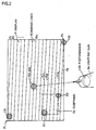
- Fig. 2 shows an example of the layout of sensors on the display surface.
- the sensor LS1 forming a start position sensor is located, for example, at position P1 at the top left corner of the display, which is the initial scanning position of the scanning line.
- the sensor LS1 is located in a position covering at least two scanning lines such that as well as detecting the scanning line /1 which appears initially on the display surface, the sensor LS1 can also detect scanning of the adjacent scanning line /2 which scans after this scanning line /1 (the centre of the sensor is in a position corresponding to the centre point between two scanning lines /1 and /2).
- the sensor LS1 is of sufficient size to cover the two scanning lines /1 and /2, and it detects the passage of the light point of a scanning line at least two times, and outputs at least two detection signals, at an interval equal to the horizontal synchronization period.
- the sensor LS2 forming a final position sensor is located, for example, at position P2 on the bottom right of the display, which is the final scanning position of the last scanning line /n. If the player pulls the trigger of the light ray gun 3a, for example, then at the instant that the light point of the scanning line passes through the aim point PO of the light ray gun 3a, the sensor LS3 detects the light emitted from this point PO and a detection signal LP3 is output.
- sensors are, for example, positioned at the top left and bottom right corners thereof.
- sensor LS1 is located at position P1' such that it covers scanning lines /C1 and /C2
- sensor LS2 is located at position P2' such that it covers scanning line /Cn.
- Fig. 3 shows a circuit diagram from each sensor up to the input stage of the control circuit 2a.
- Sensors LS1 _ LS3 are constituted by photoelectric converter elements, such as phototransistors, or the like. When light is incident, the phototransistor cuts off and the output logic state changes.
- Inverters 111 _ 113 function as output buffers for the phototransistors. Elements other than phototransistors may be used for the sensors, provided that their output voltage or resistance value changes with the strength of received light.
- flip-flops 101 _ 106 convert the detection signals from-each sensor to signals synchronized to a CLK generated by a clock circuit 107.
- the output LP1' from sensor LS1 becomes detection signal LP1 by means of timing control according to the timing chart shown in Fig. 5 affected by flip-flops 101 and 104.
- the detection signal LP1 is synchronized to the rise of the clock CLK, and it has a cycle equal to that of the clock CLK.
- LP2' and LP3' are similarly converted to detection signals LP2 and LP3.
- the clock CLK generated by the clock circuit 107 determines the resolution in the horizontal direction of the coordinates detecting circuit. Therefore, the frequency of the clock CLK is set to a frequency whereby satisfactory resolution can be obtained, whatever the television format. For example, firstly, the maximum coordinate number in the horizontal direction, namely, the horizontal resolution in coordinates detection, is determined. The predetermined maximum coordinate is number multiplied by the horizontal synchronizing frequency of the television format having the highest horizontal synchronizing frequency of the television formats to which coordinates detection may be applied. This multiplied value is set as the oscillating frequency of the clock CLK.
- Fig. 4 shows the second stage of the control circuit 2a.
- the inverters 201 _ 203 invert the signal logic of each detection signal LP1 _ LP3.
- the flip-flops 204, 206, inverter 205 and gate 207 output a signal at level L for the period of the scanning cycle (namely, the horizontal scanning cycle), on the basis of the detection signal generated by means of sensor LS1 detecting scanning of the first scanning line after the vertical retrace ratio, and the detection signal generated by sensor LS1 detecting scanning of the next scanning line.
- Horizontal direction counter 209 comprises, for example, a counter equipped with a load function for counting up a clock CLK, and it performs a count corresponding to the horizontal coordinate value.
- the scanning cycle determining circuit 210 comprises a latch circuit, for example, which latches the output of the horizontal direction counter 209, thereby latching the count value during the scanning cycle.
- the reset circuit 211 comprises a coincidence circuit, for example, which compares the count value for the scanning cycle latched by the scanning cycle determining circuit 210 with the count value of the horizontal direction counter 209, and sets the output E to level L if the two count values agree.
- the horizontal limit circuit 212 and vertical limit circuit 216 comprise latch circuits, for example, which latch the count value of the horizontal direction counter 209 at the rise of the detection signal LP2.
- the horizontal coordinate determining circuit 213 and the vertical coordinate determining circuit 217 comprise latch circuits, for example, which latch the count value of the horizontal direction counter 209 when the detection signal LP3 corresponding to the trigger signal from the light ray gun 3a is input.
- the count value latched by the horizontal limit circuit 212 forms the horizontal limit value HLIMIT
- the count value latched by the vertical limit circuit 216 forms the vertical limit value VLIMIT.
- the count value latched by the horizontal coordinate determining circuit 213 forms the horizontal coordinate HPOS
- the count value latched by the vertical coordinate determining circuit 217 forms the vertical coordinate VPOS.
- the count values are four bits long, but the bit length may be increased freely depending on the accuracy required in the game device.
- the monitor scans the final scanning line /n (see Fig. 2).
- the sensor LS2 detects light when the light of the electron beam passes through the final scanning position P1, and it outputs a detection signal LP2'.
- the timing of this detection signal LP2' is modulated at the input stage of the control circuit 2a, and it is then input to the second stage of the control circuit 2a (see Fig. 4).
- the detection signal LP2 always clears the-flip-flops 204 and 206 (sets output Q to "0"), and sets point A and point B in Fig. 4 to level L.
- the monitor 4 starts again to scan the scanning line /1 from the initial scanning position P1 on the display D.
- Sensor LS1 detects the light point passing through it and inputs the detection signal LP1 to flip-flop 204. Consequently, point A changes to level H, whilst point B is maintained as level L.
- scanning line /2 is scanned following scanning line /1, the sensor LS1 again detects the light point passing through it and again it inputs LP1. In this case, point A is maintained at level H and point B is changed to level H.
- the-detection signal LP1 relating to scanning line /1 is supplied via the AND gate 208 to the horizontal direction counter 209 as a load pulse.
- the horizontal direction counter 209 loads the count value "0", and therefore after the load pulse has reverted to level H, it starts a count of the clock CLK.
- This count value C is supplied to the data input terminal of the scanning cycle determining circuit 210.
- the OR gate 207 supplies a pulse to the clock terminal of the scanning cycle determining circuit 210 which takes level L only for the horizontal synchronizing period between scanning lines /1 and /2.
- the count value latched when this pulse rises is the value counted during the scanning cycle. Since the scanning lines each have the same scanning cycle, the latched count value D ("5" in Fig. 6) takes a value corresponding to the scanning cycle of this image display format (horizontal synchronizing period). For example, if the oscillating frequency of the clock CLK is set to a value obtained by multiplying the horizontal synchronizing frequency of the NTSC format by the resolution N, then the count value latched by the scanning cycle determining circuit 210 will be N.
- the reset circuit 211 inputs the count value D latched by the scanning cycle determining circuit 210 to one comparative input terminal, and it inputs the count value C from the horizontal direction counter 209 to an other comparative input terminal.
- the count value D corresponding to the horizontal synchronizing period and the count value C from the horizontal direction counter 209 are compared, and if they match, in other words, if the count has reached a count value corresponding to the horizontal synchronizing period, then the reset circuit 211 output a reset signal E.
- This reset signal E resets the horizontal direction counter 209 via the AND gate 208, and therefore the horizontal direction counter 209 repeats a similar count from the start of each scanning line.
- the pulse supplied via the OR gate 207 forms a load pulse for the vertical direction counter 215, and therefore, from scanning line /2, where the output of the OR gate 207 is set to level H, the vertical direction counter 215 counts load pulses for the horizontal direction counter 209 input via the AND gate 208.
- a load pulse is output from the AND gate 208 by means of the detection signal LP1 during scanning of scanning lines /1 and /2, and by means of the reset signal E generated by the reset circuit 211 during scanning of the subsequent scanning lines. Therefore, even when the detection signal LP1 ceases to be input, the counting operation of the vertical direction counter 215 will continue each time scanning of a scanning line is completed.
- a time period equal to least one image display period is required for the light point to be detected when the trigger is pulled. If the players shoots at the top left of the screen, the trigger with be detected at the start of the image display period, whilst if the player shoots at the bottom right of the screen, the trigger will be detected at the end of the image display period.
- the light ray gun 3a outputs a detection signal LP3' at the instant that the light point passes through the position on the display at which the gun is aimed, For example, in Fig.
- the gun is aimed at position PO, so the detection signal LP3' is output at the instant that the light point passes through position PO on scanning line /m.
- the timing of the detection signal LP3' is modulated at the input stage of the control circuit 2a, whereupon it input to the control circuit 2a as a detection signal LP3 and supplied to the horizontal coordinate determining circuit 213 and the vertical coordinate determining circuit 217.
- Count value C from the horizontal direction counter 209 and count value G from the vertical direction counter 215 are supplied respectively to these determining circuits, which accordingly latch the respective count values at the rise of the detection signal LP3.
- this latched count value forms a coordinate value corresponding to the position at which the light ray gun 3a is aimed.
- the vertical coordinate determining circuit 217 latches the vertical count value from scanning line /2, in other words, the scanning line value, this latched count value forms a relative value corresponding to the position at which the light ray gun 3a is aimed.
- the divergence between two scanning lines is so slight compared to the dimensions of the display as a whole that it can be ignored in practical use.
- the values latched by the coordinate determining circuits indicate the coordinate values (HPOS, VPOS) for the point of aim of the gun when the top left corner of the display D is taken as the origin (0,0) and the coordinates are set at a prescribed resolution.
- the sensor LS2 outputs a detection signal LP2'.
- This detection signal LP2' passes through the input stage of the control circuit 2a and is supplied to the second stage of the control circuit 2a as a detection signal LP2.
- This detection signal LP2 clears the flip-flops 204, 206, as described at the beginning of this description of the operation, and also forms a latch signal for the horizontal limit circuit 212 and the vertical limit circuit 216.
- the horizontal count value C and the vertical count value G are supplied respectively to the data input terminals of the limit circuits. Thereby, the count values latched at the instant that detection signal LP2 rises form the bottom right coordinates (HLIMIT, VLIMIT) of the display D.
- the identified coordinates (HOPS, VPOS) and the limit coordinates (HLIMIT, VLIMIT) output from the control circuit 2a are supplied to the game device 1a.
- the game device 1a can determine the size of the display from the limit coordinates and it can determine the relative point of aim of the gun from the identified coordinates.
- the coordinates data processing is conducted in accordance with the game program in the game device.
- the sensors LS1 and LS2 will be located respectively at positions P1' and P2' in Fig. 2.
- the basic operation is similar to that described above. If the player shoots at any point of the subframe DC using the light ray gun 3a, the identified coordinates (HPOS, VPOS) latched by the horizontal coordinate determining circuit 213 and the vertical coordinate determining circuit 217 form relative coordinates for the point at which the gun is aimed, taking point P1' as the origin.
- the gun is fired at a region outside the subframe DC, there may be cases where the identified coordinates (HPOS, VPOS) exceed the values of the limit coordinates (HLIMIT, VLIMIT) latched by the horizontal limit circuit 212 and the vertical limit circuit 216. In this case, the game device 1a should treat the identified coordinates as invalid.
- the second mode for implementing the present invention differs from the first mode for implementing the present invention, wherein sensors are provided on a display, in that transparent sensors capable of detecting coordinates are provided on the front surface of the display.
- Fig. 7 shows the general composition of a second mode for implementing the present invention.
- the coordinates detecting device comprises: a game main unit 1b which controls a game; a monitor 4 for displaying images based on a video signal V output from the game main unit 1b; a light sensor panel 5, attached to the front surface of the monitor 4, for receiving light emitted from a light ray gun 3b; a control circuit 2b which operates as the coordinates detecting device according to the present invention; and a light ray gun 3b which is used by a player during the game to "shoot" at characters.
- the light ray gun 3b differs from the light ray gun 3a in the first mode, which was provided with a photosensor, in that it is equipped with a light-emitting diode 6 which emits light.
- the light-emitting diode 6 emits light for a time period sufficiently longer than the standard image display time period (1 field or 1 frame), and a signal ST indicating that the trigger T has been operated is output to the game main unit 1b.
- this period is sufficiently longer than the commercial power oscillating frequency and the image display vertical synchronizing period and horizontal synchronizing period.
- the element emitting light should have precise directionality, such that light can be beamed onto a particular region of the image display surface, and it should emit light having suitable characteristics for detection by the light sensor panel 5.
- the game main unit 1b has the same composition as that in the first mode, but it differs from the first mode in that it is programmed such that the coordinates signal SXY supplied from the control circuit 2b is read out when a signal ST indicating that the trigger has been operated is supplied from the light ray gun 3b.
- the monitor 4 has the same composition as that in the first mode.
- Fig. 8 shows the composition of a light sensor panel 5 corresponding to the light-detecting means of the present invention, and a control circuit 2b corresponding to the coordinates identifying means.
- the light sensor panel 5 comprises light-detecting elements arranged in the shape of a matrix. Each light-detecting element should be such that on receiving light emitted from the light ray gun 3b it outputs a detection signal corresponding to the strength of the received light.
- it may comprise solar cells Pc, or phototransistors Pt, arranged in each section of the matrix.
- any other photoelectric converter element based, for example, on a photovoltaic effect whereby an electromotive force is produced when light is received, or a photoconductive effect whereby the resistance changes when light is received, may be used, provided that there is no risk of interfering with the image on the display (the element must be transparent and have a small area).
- solar cells are used for the light-detecting elements, preferably, they should be formed by vaporization of amorphous silicon in an extremely thin layer which is shaped to produce a transparent film. This is because if it is transparent, it will not interfere with the image on the display.
- Each cell is provided with diodes to prevent reverse currents for the row output and column output, respectively.
- Each light-detecting element outputs a voltage to the matrix row m (1 ⁇ m ⁇ M) and column to which it belongs. For each row, a detection signal connecting the outputs from each light-detecting element in that row is supplied to the control circuit 2b as a vertical direction detection signal DV, and for each column, a detection signal connecting the outputs from each light-detecting element in that column is supplied to the control circuit 2b as a horizontal direction detection signal DH.
- the control device 2b comprises amplifying circuits, latch circuits and shift registers.
- the amplifying circuits 301, 302 provide an amplifying function by means of an operational amplifier, for example, which is particularly necessary when solar cells Pc are used as the light-detecting elements.
- the output voltage of each solar cell is a low voltage of about 0.5 V, and since this cannot be output directly to a digital circuit, the amplifying circuits amplify this output voltage to a level suitable for use as level H in a digital signal.
- the rate of amplification may be set by resistances R1, R2, and the cut-off frequency, by capacitor C and R1, as shown in the diagram.
- the cut-off frequency is set to a frequency whereby the commercial power frequency (50 Hz or 60 Hz, or the like,) and the image display frequency of the display (in NTSC format, vertical synchronizing frequency of 50 Hz and horizontal synchronizing frequency of 15.75 kHz) are sufficiently attenuated. Since the light sensor panel 5 also receives light from sources other than the light ray gun 3b, such as the display and fluorescent lamps or other lighting means in the room, it is necessary for the frequency components of light from these sources other than the light ray gun 3b to be attenuated.
- Latch circuits 303, 304 latch the amplified detection signals DV or DH.
- the latch timing is generated by a wired OR circuit 307.
- a wired OR circuit 307 outputs a level H signal when a level H output voltage appears in any of the signal lines for the detection signals.
- a buffer 309 supplies this level H signal to each of the latch circuits, and therefore, whenever a change is detected in the level of a detection signal, the logic state of each detection signal is latched.
- amplifying circuits are not required. However, if amplifying circuits are provided, then the signal logic is inverted, so inverters, or the like, will be necessary.
- switch circuits based on transistors, or the like may be used in place of the amplifying circuits based on operational amplifiers.
- a reference voltage which enables the switch circuits to be operated may be supplied to the negative terminal of each solar cell.
- Shift register circuits 305, 306 perform a parallel-to-serial conversion of the logic states of the detection signals latched by latch circuit 303 or 304.
- a transmitter 310 transmits serial data transferred from the shift register circuits 305, 306 to the game main unit 1b,
- a clock circuit 308 receives latch signals from the wired OR circuit 307 and generates load signals for loading data to the shift register circuits 305, 306 and a shift clock for the shift operation.
- the light-detecting element on the light sensor panel 5 which corresponds to the aim of the gun when the light was emitted.
- the light-detecting element on which the light falls changes its output voltage.
- the bits corresponding to all the signal lines for the vertical direction detection signal DV and all the signal lines for the horizontal direction detection signal DH are latched to the latch circuits 303, 304 at level H.
- the data latched to latch circuit 303 gives a coordinate in the vertical direction
- the data latched to latch circuit 304 gives a coordinate in the horizontal direction.
- These bit states are output directly to the game main unit 1b by the shift register circuits 305, 306.
- the game main unit 1b is able to obtain coordinates by reading the serial data supplied to it.
- the third mode for implementing the present invention shows a different mode for implementing the control circuit in the second mode.
- Fig. 9 shows the composition of a control circuit 2c in this third mode. Since the constituent elements other than the control circuit are of the same composition as the second mode described above (see Fig. 7), description thereof is omitted here.
- a multiplexer 401 selects each column in sequence from the vertical direction detection signal DY In accordance with a selection signal SA output from the clock circuit 409, A multiplexer 402 selects each row in sequence from the horizontal direction detection signal DH in accordance with the selection signal SA. Both multiplexers supply output signals in sequence to an amplifying circuit 403.
- the amplifying circuit 403 amplifies the output signal up to a prescribed voltage level.
- a filter 404 and a filter 405 are low-band filters provided with a cut-off frequency and attenuation characteristics whereby, respectively, the level of commercial power frequency components and the level of vertical synchronizing frequency components can be sufficiently reduced.
- a filtering function may be provided in the amplifying circuit itself, as in the amplifying circuits 301, 302 in the second mode, instead of providing the filters 404 and 405.
- a comparator 406 compares the output signal with a prescribed reference potential.
- a buffer 407 transmits the output signal after wave-shaping, and a buffer 408 transmits a clock SCLK, respectively, to the game main unit 1b.
- a clock circuit 409 outputs to the multiplexers 401, 402 a clock SCLK for data transfer and a selection signal SA and output permission signal whose contents change in synchronization with this clock.
- the third mode in addition to similar merits to the second mode described above, it is possible to reduce the number of elements comprising the circuit.
- the detection signals output from each light-detecting element in the light sensor panel 5 are time-division multiplexed before passing through the amplifier and filter, only one amplifying circuit and one filter need to be provided.
- the scanning cycle is detected by sensors located directly on an image display surface, and coordinate values are counted on this basis, it is possible to detect coordinates accurately without distinguishing between different image display formats. Namely, accurate coordinates can be obtained regardless of whether the image display format is a standard television format or an HDTV format, or whether the scanning method involves interlaced scanning or sequential scanning. Moreover, if the present invention is applied in a television device capable of displaying subframes, then since the relative coordinates within the subframe can be detected, a game can be played in the subframe, for example.
- the light-detecting means detect light emitted from the image display surface, then if this light-detecting means is positioned on the light ray gun in the game device, the position at which the player "shoots" can be obtained in the form of coordinates.
- the beamed light is converted directly into coordinates, which are therefore accurate coordinates.
- the light-detecting means outputs the transmitted light as a direct detection signal, and the coordinates identifying means converts the position at which the light is beamed to coordinate values.
Landscapes
- Engineering & Computer Science (AREA)
- Multimedia (AREA)
- Human Computer Interaction (AREA)
- Physics & Mathematics (AREA)
- Optics & Photonics (AREA)
- Position Input By Displaying (AREA)
- Length Measuring Devices By Optical Means (AREA)
Applications Claiming Priority (3)
| Application Number | Priority Date | Filing Date | Title |
|---|---|---|---|
| JP314086/95 | 1995-12-01 | ||
| JP7314086A JPH09152307A (ja) | 1995-12-01 | 1995-12-01 | 座標検出装置、その方法およびゲーム装置 |
| PCT/JP1996/003001 WO1997021071A1 (en) | 1995-12-01 | 1996-10-16 | Coordinate detecting system, method therefor and game system |
Publications (2)
| Publication Number | Publication Date |
|---|---|
| EP0807800A1 true EP0807800A1 (de) | 1997-11-19 |
| EP0807800A4 EP0807800A4 (de) | 2002-11-06 |
Family
ID=18049074
Family Applications (1)
| Application Number | Title | Priority Date | Filing Date |
|---|---|---|---|
| EP96935345A Withdrawn EP0807800A4 (de) | 1995-12-01 | 1996-10-16 | Koordinatendetektionssystem mit assoziertem verfahren und spielapparat |
Country Status (6)
| Country | Link |
|---|---|
| US (1) | US6012980A (de) |
| EP (1) | EP0807800A4 (de) |
| JP (1) | JPH09152307A (de) |
| KR (1) | KR19980701847A (de) |
| CN (1) | CN1172527A (de) |
| WO (1) | WO1997021071A1 (de) |
Cited By (2)
| Publication number | Priority date | Publication date | Assignee | Title |
|---|---|---|---|---|
| WO2001061457A1 (en) * | 2000-02-16 | 2001-08-23 | Namco Ltd. | Pointing device, program, and method for measuring pointed position |
| EP1062994A3 (de) * | 1999-06-21 | 2001-12-19 | Midway Amusement Games, LLC | Videospielsystem ausgestattet mit einer Kontrolleinheit mit Beschleunigungssensor zur Kontrolle eines Videospiels |
Families Citing this family (70)
| Publication number | Priority date | Publication date | Assignee | Title |
|---|---|---|---|---|
| US6780014B1 (en) * | 1996-11-26 | 2004-08-24 | Lightshot Systems, Inc. | Pattern testing board and system |
| US7385359B2 (en) * | 1997-08-26 | 2008-06-10 | Philips Solid-State Lighting Solutions, Inc. | Information systems |
| US7764026B2 (en) * | 1997-12-17 | 2010-07-27 | Philips Solid-State Lighting Solutions, Inc. | Systems and methods for digital entertainment |
| DE19860880B4 (de) * | 1998-02-10 | 2006-11-09 | Denso Corp., Kariya | Antrieb für Passagierschutzsystem |
| US6171190B1 (en) * | 1998-05-27 | 2001-01-09 | Act Labs, Ltd. | Photosensitive input peripheral device in a personal computer-based video gaming platform |
| JP2000218037A (ja) * | 1999-02-02 | 2000-08-08 | Sega Enterp Ltd | ビデオ画面の指示位置検出方法及び装置 |
| US7749089B1 (en) | 1999-02-26 | 2010-07-06 | Creative Kingdoms, Llc | Multi-media interactive play system |
| US20020010021A1 (en) * | 1999-08-03 | 2002-01-24 | Mccauley Jack Jean | Method and device for optical gun interaction with a computer game system |
| US20040259644A1 (en) * | 1999-08-03 | 2004-12-23 | Mccauley Jack Jean | Method and device for optical gun interaction with a computer system |
| US6663491B2 (en) * | 2000-02-18 | 2003-12-16 | Namco Ltd. | Game apparatus, storage medium and computer program that adjust tempo of sound |
| US7445550B2 (en) | 2000-02-22 | 2008-11-04 | Creative Kingdoms, Llc | Magical wand and interactive play experience |
| US6761637B2 (en) | 2000-02-22 | 2004-07-13 | Creative Kingdoms, Llc | Method of game play using RFID tracking device |
| US7878905B2 (en) | 2000-02-22 | 2011-02-01 | Creative Kingdoms, Llc | Multi-layered interactive play experience |
| JP2001252474A (ja) * | 2000-03-10 | 2001-09-18 | Namco Ltd | ゲームシステム及び情報記憶媒体 |
| US7642730B2 (en) | 2000-04-24 | 2010-01-05 | Philips Solid-State Lighting Solutions, Inc. | Methods and apparatus for conveying information via color of light |
| JP3847057B2 (ja) * | 2000-05-24 | 2006-11-15 | アルプス電気株式会社 | 指示位置検出装置及び前記装置を用いたゲーム用コントローラ |
| JP2003536045A (ja) * | 2000-06-09 | 2003-12-02 | ビームヒット,リミティド ライアビリティー カンパニー | 多種類ターゲットとシミュレートされた発射物衝突位置の視覚フィードバックを有する、小火器訓練を行う為のレーザー小火器訓練システム及び方法 |
| US7066781B2 (en) | 2000-10-20 | 2006-06-27 | Denise Chapman Weston | Children's toy with wireless tag/transponder |
| US6839049B1 (en) * | 2000-11-17 | 2005-01-04 | Intel Corporation | Physically interacting with a processor-based display |
| US6852032B2 (en) * | 2000-12-06 | 2005-02-08 | Nikon Corporation | Game machine, method of performing game and computer-readable medium |
| KR100342933B1 (ko) * | 2000-12-29 | 2002-07-03 | 전주영 | 기구물을 이용한 좌표검출장치 및 방법 |
| US20020097230A1 (en) * | 2001-01-19 | 2002-07-25 | Transvision, Inc. | Large-screen display with remote optical graphic interface |
| US6929548B2 (en) * | 2002-04-23 | 2005-08-16 | Xiaoling Wang | Apparatus and a method for more realistic shooting video games on computers or similar devices |
| JP4790930B2 (ja) * | 2001-05-30 | 2011-10-12 | 任天堂株式会社 | シューティングゲーム用コントローラおよび指示位置検出方法 |
| KR20020093291A (ko) * | 2001-06-08 | 2002-12-16 | 김범 | 스크린 상의 목표물 위치 감지 장치 |
| WO2002101318A2 (en) * | 2001-06-08 | 2002-12-19 | Beamhit, Llc | Firearm laser training system and method facilitating firearm training for extended range targets with feedback of firearm control |
| US6729731B2 (en) * | 2001-06-11 | 2004-05-04 | Info Valley Corporation | Untethered laser pointer for use with computer display |
| US7671850B2 (en) * | 2001-06-15 | 2010-03-02 | Anoto Ab | Electronic pen |
| US6902483B2 (en) * | 2002-04-01 | 2005-06-07 | Xiao Lin | Handheld electronic game device having the shape of a gun |
| US6967566B2 (en) | 2002-04-05 | 2005-11-22 | Creative Kingdoms, Llc | Live-action interactive adventure game |
| US20070066396A1 (en) | 2002-04-05 | 2007-03-22 | Denise Chapman Weston | Retail methods for providing an interactive product to a consumer |
| US20030199324A1 (en) * | 2002-04-23 | 2003-10-23 | Xiaoling Wang | Apparatus and a method for more realistic shooting video games on computers or similar devices using visible or invisible light |
| US20040002369A1 (en) * | 2002-05-06 | 2004-01-01 | Walker Jay S. | Method and apparatus for modifying a game based on results of game plays |
| US20050075166A1 (en) * | 2002-05-14 | 2005-04-07 | Hemstreet Paul A. | Media program with interactive feature |
| US20040048663A1 (en) * | 2002-09-10 | 2004-03-11 | Zeroplus Technology Co., Ltd. | Photographic pointer positioning device |
| JP2004144451A (ja) * | 2002-10-28 | 2004-05-20 | Nec Corp | 銃 |
| US9446319B2 (en) | 2003-03-25 | 2016-09-20 | Mq Gaming, Llc | Interactive gaming toy |
| KR100926074B1 (ko) * | 2003-04-30 | 2009-11-11 | 슈퍼 엘리트 테크놀로지 캄파니, 리미티드 | 좌표 검출을 수반한 입력 시스템 |
| WO2005065078A2 (en) * | 2003-11-26 | 2005-07-21 | L3 Communications Corporation | Firearm laser training system and method employing various targets to simulate training scenarios |
| JP4179162B2 (ja) * | 2003-12-26 | 2008-11-12 | 株式会社セガ | 情報処理装置、ゲーム装置、画像生成方法、ゲーム画像生成方法 |
| US20050162380A1 (en) * | 2004-01-28 | 2005-07-28 | Jim Paikattu | Laser sensitive screen |
| US20070287132A1 (en) * | 2004-03-09 | 2007-12-13 | Lamons Jason W | System and method of simulating firing of immobilization weapons |
| WO2005119356A2 (en) | 2004-05-28 | 2005-12-15 | Erik Jan Banning | Interactive direct-pointing system and calibration method |
| KR101222447B1 (ko) * | 2004-07-15 | 2013-01-15 | 큐빅 코포레이션 | 시뮬레이팅된 트레이닝 시스템들에서의 조준점의 강화 |
| TWM268089U (en) * | 2004-09-15 | 2005-06-21 | Zeroplus Technology Co Ltd | Light gun device |
| US9285897B2 (en) | 2005-07-13 | 2016-03-15 | Ultimate Pointer, L.L.C. | Easily deployable interactive direct-pointing system and calibration method therefor |
| US8313379B2 (en) | 2005-08-22 | 2012-11-20 | Nintendo Co., Ltd. | Video game system with wireless modular handheld controller |
| JP4805633B2 (ja) | 2005-08-22 | 2011-11-02 | 任天堂株式会社 | ゲーム用操作装置 |
| US7927216B2 (en) | 2005-09-15 | 2011-04-19 | Nintendo Co., Ltd. | Video game system with wireless modular handheld controller |
| JP4262726B2 (ja) * | 2005-08-24 | 2009-05-13 | 任天堂株式会社 | ゲームコントローラおよびゲームシステム |
| US8308563B2 (en) * | 2005-08-30 | 2012-11-13 | Nintendo Co., Ltd. | Game system and storage medium having game program stored thereon |
| US8157651B2 (en) | 2005-09-12 | 2012-04-17 | Nintendo Co., Ltd. | Information processing program |
| US20070160960A1 (en) * | 2005-10-21 | 2007-07-12 | Laser Shot, Inc. | System and method for calculating a projectile impact coordinates |
| US8360776B2 (en) * | 2005-10-21 | 2013-01-29 | Laser Shot, Inc. | System and method for calculating a projectile impact coordinates |
| US20070190495A1 (en) * | 2005-12-22 | 2007-08-16 | Kendir O T | Sensing device for firearm laser training system and method of simulating firearm operation with various training scenarios |
| CN100549923C (zh) * | 2006-03-03 | 2009-10-14 | 原相科技股份有限公司 | 具有影像显示器和影像传感器的定位系统 |
| US20110053120A1 (en) * | 2006-05-01 | 2011-03-03 | George Galanis | Marksmanship training device |
| US9364755B1 (en) | 2006-05-08 | 2016-06-14 | Nintendo Co., Ltd. | Methods and apparatus for using illumination marks for spatial pointing |
| JP4900914B2 (ja) * | 2006-06-15 | 2012-03-21 | 株式会社バンダイナムコゲームス | プログラム、情報記憶媒体、及び画像生成システム |
| JP5051822B2 (ja) | 2006-08-02 | 2012-10-17 | 任天堂株式会社 | 汎用遠隔制御機能を備えたゲーム装置 |
| JP5056024B2 (ja) * | 2007-01-18 | 2012-10-24 | ソニー株式会社 | 表示装置用の2次元入力装置と、表示装置、及び表示方法 |
| US20100275491A1 (en) * | 2007-03-06 | 2010-11-04 | Edward J Leiter | Blank firing barrels for semiautomatic pistols and method of repetitive blank fire |
| US20100273130A1 (en) * | 2009-04-22 | 2010-10-28 | Integrated Digital Technologies, Inc. | Shooting training systems using an embedded photo sensing panel |
| US20110216376A1 (en) * | 2010-03-05 | 2011-09-08 | Skiff, Inc. | System For And Method Of Providing Enhanced Copy Protection On A Reader Device |
| US9248370B2 (en) * | 2012-05-25 | 2016-02-02 | Phillip B. Summons | Targeting system and method for video games |
| US20160158641A1 (en) * | 2013-04-25 | 2016-06-09 | Phillip B. Summons | Targeting system and method for video games |
| US20160245624A1 (en) * | 2015-01-15 | 2016-08-25 | Philip Ian Haasnoot | Adaptive target training system |
| AU2017259954A1 (en) * | 2016-05-03 | 2018-11-08 | Performance Designed Products Llc | Video gaming system and method of operation |
| WO2023203471A1 (en) * | 2022-04-19 | 2023-10-26 | Eley Ltd. | Real-time shot detection and scoring based on target image processing |
| CN115096135A (zh) * | 2022-06-06 | 2022-09-23 | 中国人民解放军空军工程大学 | 一种四点瞄准法的训练装置及其激光定位方法 |
Family Cites Families (33)
| Publication number | Priority date | Publication date | Assignee | Title |
|---|---|---|---|---|
| US3256516A (en) * | 1962-06-20 | 1966-06-14 | Ibm | Data display centering and expansion system |
| US3440638A (en) * | 1965-04-08 | 1969-04-22 | Bendix Corp | Data display system with lateral photocell for digital repositioning of displayed data |
| FR1529608A (fr) * | 1966-12-22 | 1968-06-21 | Electronique & Radio Ind | Perfectionnements aux systèmes électroniques d'affichage de tracés sur indicateurs à balayage ligne par ligne |
| US3599221A (en) * | 1968-03-18 | 1971-08-10 | Sanders Associates Inc | Recording crt light gun and method |
| US3846826A (en) * | 1971-08-12 | 1974-11-05 | R Mueller | Direct television drawing and image manipulating system |
| JPS50138694A (de) * | 1974-04-20 | 1975-11-05 | ||
| US3960380A (en) * | 1974-09-16 | 1976-06-01 | Nintendo Co., Ltd. | Light ray gun and target changing projectors |
| US4164081A (en) * | 1977-11-10 | 1979-08-14 | The United States Of America As Represented By The Secretary Of The Navy | Remote target hit monitoring system |
| US4209832A (en) * | 1978-06-13 | 1980-06-24 | Chrysler Corporation | Computer-generated display for a fire control combat simulator |
| US4395045A (en) * | 1980-06-16 | 1983-07-26 | Sanders Associates, Inc. | Television precision target shooting apparatus and method |
| US4533144A (en) * | 1983-07-11 | 1985-08-06 | Manuel Juarez | Electronic game |
| GB2160298B (en) * | 1984-06-14 | 1987-07-15 | Ferranti Plc | Weapon aim-training apparatus |
| USH538H (en) * | 1984-12-20 | 1988-11-01 | The United States Of America As Represented By The Secretary Of The Army | Weapon firing inhibitor method and apparatus |
| JPH062186B2 (ja) * | 1985-08-30 | 1994-01-12 | 株式会社セガ・エンタ−プライゼス | 光線銃ゲ−ム機 |
| SE462404B (sv) * | 1987-03-25 | 1990-06-18 | Combinova Ab | Registreringsanordning av den elektroniska typen foer registreringsarbete vid skjutning |
| US4844476A (en) * | 1987-10-23 | 1989-07-04 | Becker James F | Video target response apparatus and method employing a standard video tape player and television receiver |
| JP2698129B2 (ja) * | 1988-11-16 | 1998-01-19 | 株式会社ナムコ | 射的ゲーム装置 |
| US4948371A (en) * | 1989-04-25 | 1990-08-14 | The United States Of America As Represented By The United States Department Of Energy | System for training and evaluation of security personnel in use of firearms |
| US5179368A (en) * | 1989-11-09 | 1993-01-12 | Lippincott Douglas E | Method and apparatus for interfacing computer light pens |
| US5119075A (en) * | 1990-06-18 | 1992-06-02 | At&T Bell Laboratories | Scheme for determining position of surface contact of cathode ray tube screen |
| JPH04102004A (ja) * | 1990-08-21 | 1992-04-03 | Kazuo Araki | 位置検出素子 |
| JPH04259482A (ja) * | 1991-02-14 | 1992-09-16 | Taito Corp | 目標位置検出装置 |
| GB9108226D0 (en) * | 1991-04-17 | 1991-06-05 | Philips Electronic Associated | Optical touch input device |
| US5215464A (en) * | 1991-11-05 | 1993-06-01 | Marshall Albert H | Aggressor shoot-back simulation |
| JP3181083B2 (ja) * | 1991-12-28 | 2001-07-03 | 任天堂株式会社 | 射撃ゲームシステムおよびそれに用いられる射撃ゲームシステムの制御方法 |
| US5194008A (en) * | 1992-03-26 | 1993-03-16 | Spartanics, Ltd. | Subliminal image modulation projection and detection system and method |
| JP3748271B2 (ja) * | 1992-05-22 | 2006-02-22 | 株式会社ナムコ | 射撃ゲーム装置 |
| US5351969A (en) * | 1992-05-26 | 1994-10-04 | Smith Engineering | Remote control system for raster scanned video display |
| GB9308663D0 (en) * | 1993-04-27 | 1993-06-16 | Link Miles Ltd | Point of incidence detection |
| US5437463A (en) * | 1994-02-14 | 1995-08-01 | Fromm; Wayne G. | Target game apparatus |
| EP1168232B1 (de) * | 1994-06-09 | 2004-03-03 | Corporation for National Research Initiatives | Hinweisvorrichtungsschittstelle |
| JPH08117447A (ja) * | 1994-10-26 | 1996-05-14 | Namco Ltd | シューティング型ゲーム装置 |
| US5823779A (en) * | 1996-05-02 | 1998-10-20 | Advanced Interactive Systems, Inc. | Electronically controlled weapons range with return fire |
-
1995
- 1995-12-01 JP JP7314086A patent/JPH09152307A/ja not_active Withdrawn
-
1996
- 1996-10-16 KR KR1019970705244A patent/KR19980701847A/ko not_active Ceased
- 1996-10-16 EP EP96935345A patent/EP0807800A4/de not_active Withdrawn
- 1996-10-16 US US08/875,623 patent/US6012980A/en not_active Expired - Fee Related
- 1996-10-16 WO PCT/JP1996/003001 patent/WO1997021071A1/ja not_active Ceased
- 1996-10-16 CN CN96191755A patent/CN1172527A/zh active Pending
Cited By (4)
| Publication number | Priority date | Publication date | Assignee | Title |
|---|---|---|---|---|
| EP1062994A3 (de) * | 1999-06-21 | 2001-12-19 | Midway Amusement Games, LLC | Videospielsystem ausgestattet mit einer Kontrolleinheit mit Beschleunigungssensor zur Kontrolle eines Videospiels |
| US6545661B1 (en) | 1999-06-21 | 2003-04-08 | Midway Amusement Games, Llc | Video game system having a control unit with an accelerometer for controlling a video game |
| WO2001061457A1 (en) * | 2000-02-16 | 2001-08-23 | Namco Ltd. | Pointing device, program, and method for measuring pointed position |
| US6677935B2 (en) | 2000-02-16 | 2004-01-13 | Namco Ltd. | Position pointing device, program, and pointed position detecting method |
Also Published As
| Publication number | Publication date |
|---|---|
| US6012980A (en) | 2000-01-11 |
| EP0807800A4 (de) | 2002-11-06 |
| CN1172527A (zh) | 1998-02-04 |
| WO1997021071A1 (en) | 1997-06-12 |
| JPH09152307A (ja) | 1997-06-10 |
| KR19980701847A (ko) | 1998-06-25 |
Similar Documents
| Publication | Publication Date | Title |
|---|---|---|
| US6012980A (en) | Coordinates detecting device, method for same and game device | |
| US7064788B2 (en) | Electronic camera with repeating flash | |
| US8144134B2 (en) | Sensing circuit, display device, and electronic apparatus | |
| KR100930008B1 (ko) | 화상 왜곡을 억제하는 이미지 센서 | |
| JP2018201155A (ja) | 固体撮像素子、撮像装置及び撮像方法 | |
| JP7108471B2 (ja) | 固体撮像素子、撮像装置及び撮像方法 | |
| WO2007119523A1 (ja) | 情報コードの表示方法及び表示装置 | |
| JP4541438B2 (ja) | 情報コードの読取装置及び読取方法 | |
| CN1094014C (zh) | 在宽宽高比屏幕上控制字幕显示的装置 | |
| JPWO2007114115A1 (ja) | 情報コードの読取装置及び読取方法並びに情報コードの表示読取システム | |
| HK1001024A (en) | Coordinate detecting system, method therefor and game system | |
| JPH10249065A (ja) | 射的ビデオゲーム装置 | |
| EP1288898A2 (de) | Einrichtung zum Steuern einer Anzeigetafel | |
| US7336310B2 (en) | Processing apparatus | |
| JPS59180588A (ja) | 表示装置の光量分布補正装置 | |
| US7800670B2 (en) | Image pickup apparatus and image pickup method | |
| KR100747875B1 (ko) | 능동 픽셀 센서 회로 | |
| RU2313919C1 (ru) | Цифровой телевизор | |
| SU1522257A1 (ru) | Устройство дл считывани графической информации | |
| KR830002605B1 (ko) | 영상 표시장치용 회선 주사 변환기 | |
| SU1552402A1 (ru) | Устройство коррекции ркостной составл ющей телевизионного сигнала | |
| JPS5911933B2 (ja) | 映像表示装置におけるライトペン指示位置検出方法 | |
| JPS6249881A (ja) | 光線銃ゲ−ム機 | |
| SU824189A1 (ru) | Устройство дл вывода информацииС элЕКТРОННОлучЕВОй ТРубКи | |
| US6683586B2 (en) | Apparatus and method of adjusting horizontal position for a video display appliance |
Legal Events
| Date | Code | Title | Description |
|---|---|---|---|
| PUAI | Public reference made under article 153(3) epc to a published international application that has entered the european phase |
Free format text: ORIGINAL CODE: 0009012 |
|
| 17P | Request for examination filed |
Effective date: 19970731 |
|
| AK | Designated contracting states |
Kind code of ref document: A1 Designated state(s): DE ES FR GB IT |
|
| A4 | Supplementary search report drawn up and despatched |
Effective date: 20020914 |
|
| AK | Designated contracting states |
Kind code of ref document: A4 Designated state(s): DE ES FR GB IT |
|
| STAA | Information on the status of an ep patent application or granted ep patent |
Free format text: STATUS: THE APPLICATION IS DEEMED TO BE WITHDRAWN |
|
| 18D | Application deemed to be withdrawn |
Effective date: 20011126 |