EP0807806A2 - Circuit de détection de rayonnement électromagnétique - Google Patents
Circuit de détection de rayonnement électromagnétique Download PDFInfo
- Publication number
- EP0807806A2 EP0807806A2 EP97106905A EP97106905A EP0807806A2 EP 0807806 A2 EP0807806 A2 EP 0807806A2 EP 97106905 A EP97106905 A EP 97106905A EP 97106905 A EP97106905 A EP 97106905A EP 0807806 A2 EP0807806 A2 EP 0807806A2
- Authority
- EP
- European Patent Office
- Prior art keywords
- circuit according
- circuit
- effect transistor
- field effect
- impedance
- Prior art date
- Legal status (The legal status is an assumption and is not a legal conclusion. Google has not performed a legal analysis and makes no representation as to the accuracy of the status listed.)
- Ceased
Links
Images
Classifications
-
- G—PHYSICS
- G08—SIGNALLING
- G08B—SIGNALLING SYSTEMS, e.g. PERSONAL CALLING SYSTEMS; ORDER TELEGRAPHS; ALARM SYSTEMS
- G08B13/00—Burglar, theft or intruder alarms
- G08B13/18—Actuation by interference with heat, light, or radiation of shorter wavelength; Actuation by intruding sources of heat, light, or radiation of shorter wavelength
- G08B13/189—Actuation by interference with heat, light, or radiation of shorter wavelength; Actuation by intruding sources of heat, light, or radiation of shorter wavelength using passive radiation detection systems
- G08B13/19—Actuation by interference with heat, light, or radiation of shorter wavelength; Actuation by intruding sources of heat, light, or radiation of shorter wavelength using passive radiation detection systems using infrared-radiation detection systems
- G08B13/191—Actuation by interference with heat, light, or radiation of shorter wavelength; Actuation by intruding sources of heat, light, or radiation of shorter wavelength using passive radiation detection systems using infrared-radiation detection systems using pyroelectric sensor means
-
- G—PHYSICS
- G01—MEASURING; TESTING
- G01J—MEASUREMENT OF INTENSITY, VELOCITY, SPECTRAL CONTENT, POLARISATION, PHASE OR PULSE CHARACTERISTICS OF INFRARED, VISIBLE OR ULTRAVIOLET LIGHT; COLORIMETRY; RADIATION PYROMETRY
- G01J1/00—Photometry, e.g. photographic exposure meter
- G01J1/42—Photometry, e.g. photographic exposure meter using electric radiation detectors
- G01J1/44—Electric circuits
-
- G—PHYSICS
- G01—MEASURING; TESTING
- G01J—MEASUREMENT OF INTENSITY, VELOCITY, SPECTRAL CONTENT, POLARISATION, PHASE OR PULSE CHARACTERISTICS OF INFRARED, VISIBLE OR ULTRAVIOLET LIGHT; COLORIMETRY; RADIATION PYROMETRY
- G01J5/00—Radiation pyrometry, e.g. infrared or optical thermometry
- G01J5/10—Radiation pyrometry, e.g. infrared or optical thermometry using electric radiation detectors
- G01J5/34—Radiation pyrometry, e.g. infrared or optical thermometry using electric radiation detectors using capacitors, e.g. pyroelectric capacitors
-
- G—PHYSICS
- G01—MEASURING; TESTING
- G01J—MEASUREMENT OF INTENSITY, VELOCITY, SPECTRAL CONTENT, POLARISATION, PHASE OR PULSE CHARACTERISTICS OF INFRARED, VISIBLE OR ULTRAVIOLET LIGHT; COLORIMETRY; RADIATION PYROMETRY
- G01J1/00—Photometry, e.g. photographic exposure meter
- G01J1/42—Photometry, e.g. photographic exposure meter using electric radiation detectors
- G01J1/44—Electric circuits
- G01J2001/4406—Plural ranges in circuit, e.g. switchable ranges; Adjusting sensitivity selecting gain values
-
- G—PHYSICS
- G01—MEASURING; TESTING
- G01J—MEASUREMENT OF INTENSITY, VELOCITY, SPECTRAL CONTENT, POLARISATION, PHASE OR PULSE CHARACTERISTICS OF INFRARED, VISIBLE OR ULTRAVIOLET LIGHT; COLORIMETRY; RADIATION PYROMETRY
- G01J1/00—Photometry, e.g. photographic exposure meter
- G01J1/42—Photometry, e.g. photographic exposure meter using electric radiation detectors
- G01J1/44—Electric circuits
- G01J2001/444—Compensating; Calibrating, e.g. dark current, temperature drift, noise reduction or baseline correction; Adjusting
-
- G—PHYSICS
- G01—MEASURING; TESTING
- G01J—MEASUREMENT OF INTENSITY, VELOCITY, SPECTRAL CONTENT, POLARISATION, PHASE OR PULSE CHARACTERISTICS OF INFRARED, VISIBLE OR ULTRAVIOLET LIGHT; COLORIMETRY; RADIATION PYROMETRY
- G01J1/00—Photometry, e.g. photographic exposure meter
- G01J1/42—Photometry, e.g. photographic exposure meter using electric radiation detectors
- G01J1/44—Electric circuits
- G01J2001/4446—Type of detector
- G01J2001/4473—Phototransistor
Definitions
- the present invention relates to a circuit for detecting electromagnetic radiation according to the preamble of claim 1. Such a circuit is in use by the applicant.
- the circuit is used to process and improve signals from sensors that are intended to detect electromagnetic radiation.
- heat radiation or infrared radiation is to be detected.
- One area of application is, for example, the field of motion detectors. These motion detectors, for example, detect people on the basis of the heat radiation they emit and, upon detection of a person, emit a signal that can be processed further in the desired manner. For example a door opener can be operated or an alarm can be triggered.
- the useful signal to be detected, the infrared radiation of the person to be detected generally changes at low frequency. The relevant range is around 1 Hz. The frequency of the useful signal results from the speed at which the infrared source passes the sensor elements.
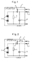
- a known circuit 1 has, for example, the structure shown in FIG. 1:
- the actual sensor element is a capacitive sensor, in particular a pyroelectric cell 2, which generates charges in accordance with the change in the intensity of the infrared radiation incident on it and stores them in the manner of a capacitor.
- One terminal of the sensor element 2 is connected to a fixed reference potential, for example ground.
- the other terminal supplies a voltage as an output signal. Since the output is extremely high-impedance, an impedance converter is connected downstream, so that the subsequent evaluation circuit sees a sufficiently low internal resistance of the circuit 1.
- a high-resistance resistor 4 is connected in parallel with the sensor element 2. It ensures that the charges formed can degrade again as soon as the heat source causing the charge has disappeared.
- the impedance converter is usually a field effect transistor 3. Its one connection is connected to the supply voltage U B , while its other connection supplies the useful signal U A suitable for further processing.
- the sensor element 2 is between ground and gate, the drain is at the battery voltage U B and the source supplies the output signal U A.
- the entire circuit is extremely susceptible to electrical interference.
- Mainly high-frequency electrical disturbances cause problems.
- High frequency is preferably understood to mean frequencies in the range of MHz and GHz.
- the high frequency interspersed over the supply lines is particularly disruptive.
- directly received radio frequency interference is also noticeable, for example caused by radio telephones or the like.
- the high-frequency interference leads to error detections and thus incorrect switching of the circuit 1.
- a capacitor 5 was used at Heimann, which was connected between the useful signal output 7 and ground. In the manner of a low-pass filter, he short-circuited high output frequencies, so that these were only weakened at the output of the circuit. The frequency of error recordings could thus be reduced.
- the object of the invention is to provide a circuit for detecting electromagnetic radiation, with which the error detections caused by high-frequency interference can be further minimized.
- FIG. 2 two sensor elements 2 are connected in series with opposite polarity.
- a discharge resistor 4 is provided parallel to the series connection of the sensor elements 2 so that the charges generated due to infrared radiation can flow off again.
- One terminal of the parallel circuit is connected to the gate of a field effect transistor 3 serving as an impedance converter.
- a first power connection of the FET supplies the output signal U A of the circuit according to the invention.
- a purely ohmic or inductive impedance 6 is connected between the second power connection of the FET and the supply voltage U B.
- the stray high-frequency voltage is injected from drain to gate via the drain-gate coupling capacitance of the field effect transistor.
- the voltage generated at the gate of the field effect transistor at the high-resistance resistor 4 and sensor element 2 is transmitted to the output 7 like the useful signal.
- Due to the additional drain impedance 6, the interspersed high-frequency voltage is divided between the drain resistance, the drain-gate coupling capacitance and the capacitance of the sensor element 2. Since the capacitive reactances are small compared to the drain impedance 6, falls the majority of the interspersed high-frequency voltage at the additional drain impedance 6.
- the drain impedance can have an ohmic resistance, an inductance or a combination of both.
- the interspersed high-frequency voltage may be divided between the inductive reactance, the drain-gate coupling capacitance and the capacitance of the sensor element 2. Since the inductive reactance increases with frequency, the high-frequency suppression is improved compared to the purely ohmic drain resistance.
- a source resistor (not shown) can be connected between output terminal 7 and ground, which supports the function of FET 3 serving as an impedance converter.
- the impedance 6 it was also considered to connect the impedance 6 between the first power terminal of the FET 3 and the output terminal 7 of the circuit 1. Even then there is the effect of suppressing high-frequency interference. The size of the output signal is then influenced in an undesirable manner, so that the first-mentioned possibility must be selected. In this case, the impedance 6 would possibly form a voltage divider with the above-mentioned source resistor, so that the output signal would be tapped off in the middle and thus weakened.
- FIG. 2 shows an embodiment in which two pyroelectric cells 2 are connected in opposite poles to one another.
- An optical system is oriented so that the two cells receive infrared radiation from different areas of the room. For example, if a person is to be detected, the orientation of the pyroelectric Cells 2 or the optics are selected so that people to be detected usually first pass through the area monitored by the first cell and then through the area monitored by the second cell. A clear alternating signal then results because the pyroelectric cells 2 do not respond one after the other, but spatially and thus chronologically. If, on the other hand, a surface to be monitored heats up uniformly, for example due to solar radiation, the output signals of the pyroelectric cells cancel each other out, so that error detections are reduced.
- a capacitor 5 acting as a low-pass filter can be provided on the output terminal, which additionally filters out high-frequency interference.
- the capacitor 5 is usually connected between the output terminal 7 and ground.
- the parallel connection of pyroelectric cells 2 and discharge resistor 4 is usually between the gate of the FET 3 and ground.
- the entire circuit can be housed in a TO-5 package. Only the connections for the supply voltage, for ground and for the useful signal then appear to the outside.
- the housing has a window through which the pyroelectric cells receive the thermal radiation to be detected.
- the pyroelectric cells have a sensitivity of the order of about 3.5 kV / W, at 0.5 ⁇ W, this results in a voltage of less than 2 mV with a high internal resistance.
- the resistor 4 has a value between 20 G ⁇ and 300 G ⁇ , preferably 75 G ⁇ . That of the invention
- High-frequency suppression impedance 6 has an ohmic component between 100 ⁇ and 470 k ⁇ , preferably 10 k ⁇ . But it can also be purely inductive.
- FET 3 is typically an n-channel junction FET, but n-channel depletion MOSFETs can also be used, for example.
- the capacitor 5 has a capacitance in the range between 100 pF and 10 nF, preferably of 270 pF.
- the FET typically has a voltage gain less than 1, typically about 0.9.
- the signal present at the output terminal 7 can then be further processed by suitable subsequent circuits, for example operational amplifiers.
- suitable subsequent circuits for example operational amplifiers.
- the source resistance mentioned above would be part of such an external circuit.
Landscapes
- Physics & Mathematics (AREA)
- General Physics & Mathematics (AREA)
- Spectroscopy & Molecular Physics (AREA)
- Engineering & Computer Science (AREA)
- Power Engineering (AREA)
- Photometry And Measurement Of Optical Pulse Characteristics (AREA)
- Geophysics And Detection Of Objects (AREA)
- Radiation Pyrometers (AREA)
- Transforming Light Signals Into Electric Signals (AREA)
- Light Receiving Elements (AREA)
Applications Claiming Priority (2)
| Application Number | Priority Date | Filing Date | Title |
|---|---|---|---|
| DE19619459A DE19619459C2 (de) | 1996-05-14 | 1996-05-14 | Schaltung zur Erfassung elektromagnetischer Strahlung |
| DE19619459 | 1996-05-14 |
Publications (2)
| Publication Number | Publication Date |
|---|---|
| EP0807806A2 true EP0807806A2 (fr) | 1997-11-19 |
| EP0807806A3 EP0807806A3 (fr) | 1999-09-22 |
Family
ID=7794310
Family Applications (1)
| Application Number | Title | Priority Date | Filing Date |
|---|---|---|---|
| EP97106905A Ceased EP0807806A3 (fr) | 1996-05-14 | 1997-04-25 | Circuit de détection de rayonnement électromagnétique |
Country Status (6)
| Country | Link |
|---|---|
| US (1) | US6013914A (fr) |
| EP (1) | EP0807806A3 (fr) |
| JP (1) | JPH1048043A (fr) |
| KR (1) | KR100516529B1 (fr) |
| DE (1) | DE19619459C2 (fr) |
| TW (1) | TW419583B (fr) |
Cited By (1)
| Publication number | Priority date | Publication date | Assignee | Title |
|---|---|---|---|---|
| WO2014025606A1 (fr) * | 2012-08-08 | 2014-02-13 | Excelitas Technologies Singapore, Pte. Ltd. | Détecteur de filtration d'interférence électromagnétique (emi) et son procédé |
Families Citing this family (4)
| Publication number | Priority date | Publication date | Assignee | Title |
|---|---|---|---|---|
| DE19962938A1 (de) * | 1999-12-24 | 2001-07-19 | Perkinelmer Optoelectronics | Verfahren zum Korrigieren des Ausgangssignals eines Infrarotstrahlungsmehrelementsensors, Infrarotstrahlungsmehrelementsensor und Infrarotstrahlungsmehrelementsensorsystem |
| FR2808442B1 (fr) * | 2000-05-04 | 2002-07-05 | Silab Sa | Procede d'extraction d'un principe actif a partir de teguments de pomme, principe actif obtenu et composition adaptee pour lutter contre les consequences du stress oxydatif de la peau |
| US20130032718A1 (en) * | 2011-08-03 | 2013-02-07 | Robert Bosch Gmbh | Rf immunity improved pyro sensor |
| EP3540391A4 (fr) * | 2016-11-14 | 2020-06-03 | Murata Manufacturing Co., Ltd. | Circuit de détection infrarouge et capteur infrarouge |
Family Cites Families (8)
| Publication number | Priority date | Publication date | Assignee | Title |
|---|---|---|---|---|
| JPS60125530A (ja) * | 1983-12-09 | 1985-07-04 | Kureha Chem Ind Co Ltd | 赤外線センサ |
| DE3413921A1 (de) * | 1984-04-13 | 1985-10-24 | Preh, Elektrofeinmechanische Werke Jakob Preh Nachf. Gmbh & Co, 8740 Bad Neustadt | Verfahren zur herstellung eines infrarotdetektors |
| GB2170952B (en) * | 1985-02-08 | 1988-11-16 | Philips Electronic Associated | Infra-red radiation detector devices |
| DE3528646C3 (de) * | 1985-08-09 | 1994-04-07 | Hirschmann Richard Gmbh Co | Schaltungsanordnung für einen Infrarot-Raumüberwachungsdetektor |
| DE3537316C1 (de) * | 1985-10-19 | 1987-03-12 | Hirschmann Radiotechnik | Schaltungsanordnung fuer einen Infrarot-Raumueberwachungsdetektor |
| JPH0530105Y2 (fr) * | 1987-05-29 | 1993-08-02 | ||
| JPH02130431A (ja) * | 1988-11-11 | 1990-05-18 | Nippon Ceramic Co Ltd | 焦電型赤外線センサ |
| US5352895A (en) * | 1992-02-19 | 1994-10-04 | Nohmi Bosai Ltd. | Pyroelectric device |
-
1996
- 1996-05-14 DE DE19619459A patent/DE19619459C2/de not_active Expired - Lifetime
-
1997
- 1997-04-25 EP EP97106905A patent/EP0807806A3/fr not_active Ceased
- 1997-05-12 KR KR1019970018302A patent/KR100516529B1/ko not_active Expired - Lifetime
- 1997-05-13 TW TW086106505A patent/TW419583B/zh not_active IP Right Cessation
- 1997-05-14 US US08/855,671 patent/US6013914A/en not_active Expired - Lifetime
- 1997-05-14 JP JP9124543A patent/JPH1048043A/ja active Pending
Cited By (1)
| Publication number | Priority date | Publication date | Assignee | Title |
|---|---|---|---|---|
| WO2014025606A1 (fr) * | 2012-08-08 | 2014-02-13 | Excelitas Technologies Singapore, Pte. Ltd. | Détecteur de filtration d'interférence électromagnétique (emi) et son procédé |
Also Published As
| Publication number | Publication date |
|---|---|
| DE19619459C2 (de) | 2000-06-08 |
| EP0807806A3 (fr) | 1999-09-22 |
| JPH1048043A (ja) | 1998-02-20 |
| TW419583B (en) | 2001-01-21 |
| KR970075861A (ko) | 1997-12-10 |
| KR100516529B1 (ko) | 2006-01-12 |
| US6013914A (en) | 2000-01-11 |
| DE19619459A1 (de) | 1997-11-20 |
Similar Documents
| Publication | Publication Date | Title |
|---|---|---|
| DE10131243C1 (de) | Kapazitiver Näherungsschalter | |
| EP0049493B1 (fr) | Détecteur d'intrusion à infrarouge | |
| EP2241868B1 (fr) | Circuit destiné à la détermination d'une capacité de mesure | |
| EP2069730B1 (fr) | Dispositif de determination et/ou de surveillance d'une grandeur de procede | |
| DE69425752T2 (de) | Kapazitiver detektor und alarmsystem | |
| DE102007047887A1 (de) | Kapazitätserfassungsvorrichtung | |
| DE69515459T2 (de) | Kapazitiver Sensor | |
| DE3852431T2 (de) | Einbruchdetektorsystem. | |
| EP3457369B1 (fr) | Circuit pour capteur de fumée | |
| EP1194740B1 (fr) | Capteur electrique permettant la mesure d'un changement de capacite et la conversion en un signal de tension | |
| DE3809960C2 (fr) | ||
| DE1766889A1 (de) | Detektoranordnung | |
| EP0807806A2 (fr) | Circuit de détection de rayonnement électromagnétique | |
| DE69312982T2 (de) | Pyroelektrische Vorrichtung | |
| DE102008047434A1 (de) | Verfahren und Schaltung zur Detektion einer Annäherung an eine Elektrodeneinrichtung | |
| CH661135A5 (de) | Vorrichtung zum ueberwachen von gepanzerten raeumen, insbesondere von tresoren und kassenschraenken, und zum erzeugen eines alarmsignales, wenn ein einbruchversuch unternommen wird. | |
| DE19913655B4 (de) | Verstärkerschaltung für einen Infrarotsensor | |
| EP1164380B1 (fr) | Circuit pout détecter des changements de capacitance | |
| DE102009053077B3 (de) | Kapazitive Näherungssensoranordnung | |
| EP0043516A2 (fr) | Dispositif électrique de filtrage | |
| EP0086369A1 (fr) | Détecteur infra-rouge d'intrusion avec récepteur à rayonnement pyroélectrique | |
| DE2453439A1 (de) | Kapazitiver fuehler fuer automatische tueren | |
| DE3404151C2 (fr) | ||
| WO2004048956A1 (fr) | Circuiterie pour l'evaluation de capteurs et procede pour evaluer plusieurs capteurs | |
| DE19637357C1 (de) | Vorrichtung zum Schutz vor elektromagnetischer Störstrahlung |
Legal Events
| Date | Code | Title | Description |
|---|---|---|---|
| PUAI | Public reference made under article 153(3) epc to a published international application that has entered the european phase |
Free format text: ORIGINAL CODE: 0009012 |
|
| AK | Designated contracting states |
Kind code of ref document: A2 Designated state(s): DE FR GB IT NL |
|
| PUAL | Search report despatched |
Free format text: ORIGINAL CODE: 0009013 |
|
| AK | Designated contracting states |
Kind code of ref document: A3 Designated state(s): DE FR GB IT NL |
|
| RIC1 | Information provided on ipc code assigned before grant |
Free format text: 6G 01J 1/44 A, 6G 08B 13/191 B, 6G 01J 5/34 B |
|
| 17P | Request for examination filed |
Effective date: 20000313 |
|
| RAP1 | Party data changed (applicant data changed or rights of an application transferred) |
Owner name: PERKINELMER OPTOELECTRONICS GMBH |
|
| RAP1 | Party data changed (applicant data changed or rights of an application transferred) |
Owner name: PERKINELMER OPTOELECTRONICS GMBH |
|
| 17Q | First examination report despatched |
Effective date: 20040406 |
|
| STAA | Information on the status of an ep patent application or granted ep patent |
Free format text: STATUS: THE APPLICATION HAS BEEN REFUSED |
|
| 18R | Application refused |
Effective date: 20060526 |