EP0807830A1 - Optical radar device, particularly for vehicles - Google Patents
Optical radar device, particularly for vehicles Download PDFInfo
- Publication number
- EP0807830A1 EP0807830A1 EP97107956A EP97107956A EP0807830A1 EP 0807830 A1 EP0807830 A1 EP 0807830A1 EP 97107956 A EP97107956 A EP 97107956A EP 97107956 A EP97107956 A EP 97107956A EP 0807830 A1 EP0807830 A1 EP 0807830A1
- Authority
- EP
- European Patent Office
- Prior art keywords
- radar device
- optical radar
- optical
- foregoing
- plane
- Prior art date
- Legal status (The legal status is an assumption and is not a legal conclusion. Google has not performed a legal analysis and makes no representation as to the accuracy of the status listed.)
- Withdrawn
Links
- 230000003287 optical effect Effects 0.000 title claims abstract description 59
- 230000005670 electromagnetic radiation Effects 0.000 claims description 2
- 239000011159 matrix material Substances 0.000 claims description 2
- 239000012780 transparent material Substances 0.000 claims description 2
- 239000004065 semiconductor Substances 0.000 abstract 1
- 230000005855 radiation Effects 0.000 description 3
- 230000004075 alteration Effects 0.000 description 2
- 230000010355 oscillation Effects 0.000 description 2
- 230000005540 biological transmission Effects 0.000 description 1
- 230000015556 catabolic process Effects 0.000 description 1
- 238000010586 diagram Methods 0.000 description 1
- 230000001771 impaired effect Effects 0.000 description 1
- 230000000704 physical effect Effects 0.000 description 1
Images

Classifications
-
- B—PERFORMING OPERATIONS; TRANSPORTING
- B60—VEHICLES IN GENERAL
- B60Q—ARRANGEMENT OF SIGNALLING OR LIGHTING DEVICES, THE MOUNTING OR SUPPORTING THEREOF OR CIRCUITS THEREFOR, FOR VEHICLES IN GENERAL
- B60Q1/00—Arrangement of optical signalling or lighting devices, the mounting or supporting thereof or circuits therefor
- B60Q1/0017—Devices integrating an element dedicated to another function
- B60Q1/0023—Devices integrating an element dedicated to another function the element being a sensor, e.g. distance sensor, camera
-
- G—PHYSICS
- G01—MEASURING; TESTING
- G01S—RADIO DIRECTION-FINDING; RADIO NAVIGATION; DETERMINING DISTANCE OR VELOCITY BY USE OF RADIO WAVES; LOCATING OR PRESENCE-DETECTING BY USE OF THE REFLECTION OR RERADIATION OF RADIO WAVES; ANALOGOUS ARRANGEMENTS USING OTHER WAVES
- G01S17/00—Systems using the reflection or reradiation of electromagnetic waves other than radio waves, e.g. lidar systems
- G01S17/88—Lidar systems specially adapted for specific applications
- G01S17/93—Lidar systems specially adapted for specific applications for anti-collision purposes
- G01S17/931—Lidar systems specially adapted for specific applications for anti-collision purposes of land vehicles
-
- G—PHYSICS
- G01—MEASURING; TESTING
- G01S—RADIO DIRECTION-FINDING; RADIO NAVIGATION; DETERMINING DISTANCE OR VELOCITY BY USE OF RADIO WAVES; LOCATING OR PRESENCE-DETECTING BY USE OF THE REFLECTION OR RERADIATION OF RADIO WAVES; ANALOGOUS ARRANGEMENTS USING OTHER WAVES
- G01S7/00—Details of systems according to groups G01S13/00, G01S15/00, G01S17/00
- G01S7/48—Details of systems according to groups G01S13/00, G01S15/00, G01S17/00 of systems according to group G01S17/00
- G01S7/481—Constructional features, e.g. arrangements of optical elements
- G01S7/4811—Constructional features, e.g. arrangements of optical elements common to transmitter and receiver
-
- G—PHYSICS
- G01—MEASURING; TESTING
- G01S—RADIO DIRECTION-FINDING; RADIO NAVIGATION; DETERMINING DISTANCE OR VELOCITY BY USE OF RADIO WAVES; LOCATING OR PRESENCE-DETECTING BY USE OF THE REFLECTION OR RERADIATION OF RADIO WAVES; ANALOGOUS ARRANGEMENTS USING OTHER WAVES
- G01S7/00—Details of systems according to groups G01S13/00, G01S15/00, G01S17/00
- G01S7/48—Details of systems according to groups G01S13/00, G01S15/00, G01S17/00 of systems according to group G01S17/00
- G01S7/481—Constructional features, e.g. arrangements of optical elements
- G01S7/4817—Constructional features, e.g. arrangements of optical elements relating to scanning
-
- G—PHYSICS
- G02—OPTICS
- G02B—OPTICAL ELEMENTS, SYSTEMS OR APPARATUS
- G02B5/00—Optical elements other than lenses
- G02B5/08—Mirrors
- G02B5/10—Mirrors with curved faces
Definitions
- the present invention relates to an optical radar device, particularly for road vehicles.
- a driver alert System is desirable to locate hazardously close vehicles or other obstacles.
- a radar is a device for measuring the distance of a target (the obstacle to be located) by determining the time interval between the transmission of electromagnetic radiation by the radar and reception by the radar of the radiation reflected by the obstacle.
- Optical radars normally comprise a laser source; a photodetecting device; and an optical beam forming and directing system, in turn comprising a flat reflecting mirror for receiving the radiation emitted by the laser and by one or more lenses through which the beam received and reflected by the flat mirror travels.
- a similar lens and flat mirror system receives the radiation reflected by the obstacle and focuses it on to the photodetecting device.
- each optical element inevitably reduces the intensity of the electromagnetic beam traveling through it, the presence of lenses impairs the efficiency of the system, as well as the optical quality of the beam due to aberration phenomena.
- an optical radar device in particular for vehicles, comprising emitting means for emitting a first electromagnetic beam on to a target; detecting means for detecting a second electromagnetic beam generated by reflection of said first beam by the target; and beam forming means for imparting a given path and given direction to said first beam, and for receiving and focusing said second beam on to said detecting means; characterized in that said beam forming means comprise at least one reflecting element having optical power.
- Number 1 in Figure 1 indicates a known optical radar housed, according to one aspect of the present invention, inside two vehicle headlights 2a, 2b.
- Radar 1 comprises a laser diode 3 for generating a first electromagnetic beam 4; a photodetector 6 for detecting a second electromagnetic beam 7 generated by reflection of first beam 4 by a target 5; and an optical beam forming system 9 for directing first beam 4 in a given direction along a propagation path D (indicated by the arrow) and focusing second beam 7 on to photodetector 6, which is connected to a processing system 8 for supplying data relative to the distance of the detected target.
- a propagation path D indicated by the arrow
- first beam 4 comprises elliptical sections with different angles of divergency along the two optical axes.
- first beam 4 comprises a train of pulses 14, of predetermined duration, frequency and power, generated by a pulsing system 15, but, according to a variation not shown, may also be a continuous modulated beam.
- Second beam 7 comprises a portion of first beam 4 reflected by target 5 and within an optical cone of given size determined by beam forming system 9 and in turn defining the receiving "field".
- beam forming system 9 comprises two curved mirrors 10, 11 with respective reflecting surfaces 12, 13, which are so shaped as to have a hyperbolic profile in each vertical section, and a parabolic or hyperbolic profile in each horizontal section, as shown in Figure 4, wherein a vertical section plane ⁇ and a horizontal section plane ⁇ cut reflecting surfaces 12, 13 of mirrors 10, 11 along a first hyperbolic curve 24 and a second parabolic or hyperbolic curve 25 respectively.
- reflecting surfaces 12, 13 may also be obtained by rotating a parabolic surface about its axis of symmetry.
- first beam 4 in the Figure 2 and 3 sections respectively defines angles of divergency ⁇ elev,Tx and ⁇ azimuth,Tx
- the receiving field is defined respectively by angles ⁇ elev,Rx and ⁇ azimuth,Rx .
- Angle ⁇ elev,Tx is preferably much greater than angle ⁇ azimuth,Tx to obtain a horizontally narrow, vertically wide beam.
- a horizontally narrow beam is advantageous in the case of a scanning radar, by also enabling information to be obtained concerning the location and size of the target in the scanning plane, e.g. the horizontal plane in the case of a ground vehicle.
- Diffracting optics 16 provide for directing the beam in predetermined directions and varying its physical properties and intensity, depending on how they are structured. More generally speaking, the capacity of an optical component to vary certain basic quantities of an electromagnetic beam, such as form, intensity and direction of propagation, is known as "optical power".
- Diffraction optics 16 may comprise a matrix of adjacent diffracting microoptics 17, and may either be formed on a film of transparent material 18 bonded to reflecting surfaces 12, 13 of mirrors 10, 11, or directly on reflecting surfaces 12, 13 themselves.
- Relief diffracting optics e.g. computer-generated holograms, are one example of diffracting optics which may be used for the optical radar of the invention.
- Beams 4 and 7 may be modified as required by the device according to the invention using curved mirrors of the type described with or without diffracting optics, or flat mirrors with diffracting optics.
- the optical radar device is installed inside one of the vehicle headlights in a substantially monostatic configuration.
- the device may be divided into two subassemblies, one containing the emitting part of the radar (laser 3 and first curved mirror 10), and the other containing the receiving part (second curved mirror 11 and photodetector 6); and each subsystem is housed inside a respective headlight 2a, 2b in a substantially bistatic configuration.
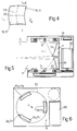
- the optical radar may be equipped with a beam scanning system 19 wherein actuating and supporting means 20 and 22 move the mirrors with respect to laser 3 and photodetector 6, which are fixed.
- mirrors 10, 11 may be mounted to swing about an axis r through both laser 3 and photodetector 6; and a motor 20 provides, in a manner not shown, for oscillating mirrors 10, 11 about a balance position.
- first electromagnetic beam 4 emitted by laser 3 and reflected by mirror 10 travels along path D and gets wider by angles ⁇ elev,Tx and ⁇ azimuth,Tx in the directions defined by its optical axes; and mirror 11 focuses second beam 7 on photodetector 6, which converts the light signal into and electric signal and transmits it to processing system 8.
- the oscillation of mirrors 10 and 11 in the variation shown by the dotted line in Figure 5, or rotation of mirrors 10a, 10b, 10c and 11a, 11b, 11c in the preferred embodiment in Figures 5 and 6 provides for horizontally scanning first beam 4.
- the angular resolution of the optical radar is determined by the oscillation speed (swing system) or rotation speed (Figure 6 system) of the mirrors, which is understandable in the case of pulsed radars, the angular resolution of which is determined by the angle between two successive pulses and which is proportional to the speed of the mirrors.
- the curved mirrors described (or at any rate mirrors having optical power by virtue of diffracting optics 16) provide for eliminating the lenses of optical radars, which are thus simplified, made more compact, and may therefore be installed in confined spaces, such as headlights or fog lights.
- Eliminating the lenses also provides for improvements in terms of performance by reducing system losses and aberration.
Landscapes
- Engineering & Computer Science (AREA)
- Physics & Mathematics (AREA)
- General Physics & Mathematics (AREA)
- Computer Networks & Wireless Communication (AREA)
- Radar, Positioning & Navigation (AREA)
- Remote Sensing (AREA)
- Mechanical Engineering (AREA)
- Optics & Photonics (AREA)
- Electromagnetism (AREA)
- Optical Radar Systems And Details Thereof (AREA)
- Radar Systems Or Details Thereof (AREA)
Applications Claiming Priority (2)
| Application Number | Priority Date | Filing Date | Title |
|---|---|---|---|
| IT96TO000413A IT1285332B1 (it) | 1996-05-17 | 1996-05-17 | Dispositivo radar di tipo ottico, in particolare per un veicolo. |
| ITTO960413 | 1996-05-17 |
Publications (1)
| Publication Number | Publication Date |
|---|---|
| EP0807830A1 true EP0807830A1 (en) | 1997-11-19 |
Family
ID=11414640
Family Applications (1)
| Application Number | Title | Priority Date | Filing Date |
|---|---|---|---|
| EP97107956A Withdrawn EP0807830A1 (en) | 1996-05-17 | 1997-05-15 | Optical radar device, particularly for vehicles |
Country Status (2)
| Country | Link |
|---|---|
| EP (1) | EP0807830A1 (it) |
| IT (1) | IT1285332B1 (it) |
Cited By (8)
| Publication number | Priority date | Publication date | Assignee | Title |
|---|---|---|---|---|
| US6280057B1 (en) | 1997-12-17 | 2001-08-28 | O'meara James C. | Laser lighting system |
| EP0957376A3 (en) * | 1998-05-13 | 2003-01-22 | Olympus Optical Co., Ltd. | Distance measuring apparatus |
| GB2392035A (en) * | 2002-07-16 | 2004-02-18 | Visteon Global Tech Inc | Vehicle lamp incorporating a sensor and data transmission means |
| US9103904B2 (en) | 2013-04-30 | 2015-08-11 | Uchicago Argonne, Llc | Interferometric millimeter wave and THz wave doppler radar |
| CN104986116A (zh) * | 2015-07-21 | 2015-10-21 | 张进 | 带有激光雷达的汽车外后视镜和汽车 |
| CN106524036A (zh) * | 2012-02-07 | 2017-03-22 | 两树光子学有限公司 | 具有相位调制器的用于车前灯的照明设备 |
| CN107015239A (zh) * | 2017-05-19 | 2017-08-04 | 深圳市帝泰光电有限公司 | 一种雷达波穿透成像系统 |
| CN110515057A (zh) * | 2019-04-10 | 2019-11-29 | 青岛镭测创芯科技有限公司 | 一种收发一体的多方向光学准直收发装置 |
Citations (3)
| Publication number | Priority date | Publication date | Assignee | Title |
|---|---|---|---|---|
| US3781552A (en) * | 1972-08-02 | 1973-12-25 | K Kadrmas | Self-calibrating multiple field of view telescope for remote atmospheric electromagnetic probing and data acquisition |
| EP0384353A2 (en) * | 1989-02-20 | 1990-08-29 | Omron Corporation | Reflective-type photoelectric sensor |
| US5313262A (en) * | 1992-09-30 | 1994-05-17 | Imra America, Inc. | Systems and methods for object detection using beam widening optics |
-
1996
- 1996-05-17 IT IT96TO000413A patent/IT1285332B1/it active IP Right Grant
-
1997
- 1997-05-15 EP EP97107956A patent/EP0807830A1/en not_active Withdrawn
Patent Citations (3)
| Publication number | Priority date | Publication date | Assignee | Title |
|---|---|---|---|---|
| US3781552A (en) * | 1972-08-02 | 1973-12-25 | K Kadrmas | Self-calibrating multiple field of view telescope for remote atmospheric electromagnetic probing and data acquisition |
| EP0384353A2 (en) * | 1989-02-20 | 1990-08-29 | Omron Corporation | Reflective-type photoelectric sensor |
| US5313262A (en) * | 1992-09-30 | 1994-05-17 | Imra America, Inc. | Systems and methods for object detection using beam widening optics |
Cited By (20)
| Publication number | Priority date | Publication date | Assignee | Title |
|---|---|---|---|---|
| US6280057B1 (en) | 1997-12-17 | 2001-08-28 | O'meara James C. | Laser lighting system |
| EP0957376A3 (en) * | 1998-05-13 | 2003-01-22 | Olympus Optical Co., Ltd. | Distance measuring apparatus |
| GB2392035A (en) * | 2002-07-16 | 2004-02-18 | Visteon Global Tech Inc | Vehicle lamp incorporating a sensor and data transmission means |
| GB2392035B (en) * | 2002-07-16 | 2004-08-11 | Visteon Global Tech Inc | Vehicle lamp and vehicle illumination and data transmission system incorporating same |
| US6821003B2 (en) | 2002-07-16 | 2004-11-23 | Visteon Global Technologies, Inc. | Vehicle lamp and vehicle illumination and data transmission system incorporating same |
| US10451742B2 (en) | 2012-02-07 | 2019-10-22 | Envisics Ltd. | Holographic LIDAR system |
| CN106524036B (zh) * | 2012-02-07 | 2019-11-26 | 恩维世科斯有限公司 | 具有相位调制器的用于车前灯的照明设备 |
| CN106524036A (zh) * | 2012-02-07 | 2017-03-22 | 两树光子学有限公司 | 具有相位调制器的用于车前灯的照明设备 |
| EP3165815A1 (en) * | 2012-02-07 | 2017-05-10 | Two Trees Photonics Limited | A light detection and ranging sytem lidar as part of collision avoidance system with a phase modulator |
| US11003137B2 (en) | 2012-02-07 | 2021-05-11 | Envisics Ltd | Holographic lidar system and method |
| US9829858B2 (en) | 2012-02-07 | 2017-11-28 | Daqri Holographics Limited | Lighting device for headlights with a phase modulator |
| US10061268B2 (en) | 2012-02-07 | 2018-08-28 | Envisics Ltd. | Lighting device for headlights with a phase modulator |
| US10061267B2 (en) | 2012-02-07 | 2018-08-28 | Envisics Ltd. | Lighting device for headlights with a phase modulator |
| US10061266B2 (en) | 2012-02-07 | 2018-08-28 | Envisics Ltd. | Holographic lidar system |
| US10228654B2 (en) | 2012-02-07 | 2019-03-12 | Envisics Ltd. | Lighting device for headlights with a phase modulator |
| US9103904B2 (en) | 2013-04-30 | 2015-08-11 | Uchicago Argonne, Llc | Interferometric millimeter wave and THz wave doppler radar |
| CN104986116A (zh) * | 2015-07-21 | 2015-10-21 | 张进 | 带有激光雷达的汽车外后视镜和汽车 |
| CN107015239A (zh) * | 2017-05-19 | 2017-08-04 | 深圳市帝泰光电有限公司 | 一种雷达波穿透成像系统 |
| CN110515057A (zh) * | 2019-04-10 | 2019-11-29 | 青岛镭测创芯科技有限公司 | 一种收发一体的多方向光学准直收发装置 |
| CN110515057B (zh) * | 2019-04-10 | 2024-11-26 | 青岛镭测创芯科技有限公司 | 一种收发一体的多方向光学准直收发装置 |
Also Published As
| Publication number | Publication date |
|---|---|
| ITTO960413A0 (it) | 1996-05-17 |
| IT1285332B1 (it) | 1998-06-03 |
| ITTO960413A1 (it) | 1997-11-17 |
Similar Documents
| Publication | Publication Date | Title |
|---|---|---|
| US7544945B2 (en) | Vertical cavity surface emitting laser (VCSEL) array laser scanner | |
| US5784023A (en) | Speed detection method | |
| CA2049578C (en) | Collision avoidance system | |
| US5313262A (en) | Systems and methods for object detection using beam widening optics | |
| US6246502B1 (en) | Optical scanning apparatus | |
| US11732858B2 (en) | Headlight illumination system using optical element | |
| KR102407344B1 (ko) | 확장된 수평 시야각을 가지는 스캐닝 라이다 장치 | |
| US20040114205A1 (en) | Laser scanner with peripheral scanning capability | |
| JPH09113262A (ja) | 走査距離計及び距離計を使用する走査方法 | |
| US12372625B2 (en) | Position capturing device for a light signal redirection device of an optical measurement apparatus for capturing objects, light signal redirection device, measurement apparatus and method for operating a position capturing device | |
| JP2005121638A (ja) | 光電子検出装置 | |
| EP0807830A1 (en) | Optical radar device, particularly for vehicles | |
| US5260710A (en) | Vehicular optical-radar apparatus | |
| JP2003121546A (ja) | 車載用レーダ装置 | |
| CN116457698A (zh) | 一种激光雷达及移动平台 | |
| WO1999026214A1 (en) | Device and method for detection of aircraft wire hazard | |
| JP2024546427A (ja) | 可視光、LiDAR、およびレーダ放射を放出するためのヴィークル用のマルチスペクトル放出デバイス、ならびにその方法および使用 | |
| JPH11142112A (ja) | 距離測定装置 | |
| JP4379790B2 (ja) | 光景を走査する装置 | |
| JP3810045B2 (ja) | レーダ装置 | |
| CA2296837A1 (en) | Collision avoidance system | |
| US12386042B2 (en) | Light signal deflecting device for an optical measuring system for detecting objects, measuring system, and method for operating a light signal deflecting device | |
| JPH11326498A (ja) | 車両用光レーダ装置 | |
| JPH06242224A (ja) | 車載用障害物検知装置 | |
| KR102486473B1 (ko) | 차량용 스캐닝 라이다 광학계 및 그를 포함하는 차량용 스캐닝 라이다 |
Legal Events
| Date | Code | Title | Description |
|---|---|---|---|
| PUAI | Public reference made under article 153(3) epc to a published international application that has entered the european phase |
Free format text: ORIGINAL CODE: 0009012 |
|
| AK | Designated contracting states |
Kind code of ref document: A1 Designated state(s): DE ES FR GB |
|
| 17P | Request for examination filed |
Effective date: 19971029 |
|
| 17Q | First examination report despatched |
Effective date: 19980112 |
|
| STAA | Information on the status of an ep patent application or granted ep patent |
Free format text: STATUS: THE APPLICATION IS DEEMED TO BE WITHDRAWN |
|
| 18D | Application deemed to be withdrawn |
Effective date: 20001201 |