EP0807875A1 - Méthode et dispostif de commande d'une ligne de fabrication - Google Patents
Méthode et dispostif de commande d'une ligne de fabrication Download PDFInfo
- Publication number
- EP0807875A1 EP0807875A1 EP97107679A EP97107679A EP0807875A1 EP 0807875 A1 EP0807875 A1 EP 0807875A1 EP 97107679 A EP97107679 A EP 97107679A EP 97107679 A EP97107679 A EP 97107679A EP 0807875 A1 EP0807875 A1 EP 0807875A1
- Authority
- EP
- European Patent Office
- Prior art keywords
- control unit
- work
- memory
- data
- information
- Prior art date
- Legal status (The legal status is an assumption and is not a legal conclusion. Google has not performed a legal analysis and makes no representation as to the accuracy of the status listed.)
- Granted
Links
Images


Classifications
-
- G—PHYSICS
- G05—CONTROLLING; REGULATING
- G05B—CONTROL OR REGULATING SYSTEMS IN GENERAL; FUNCTIONAL ELEMENTS OF SUCH SYSTEMS; MONITORING OR TESTING ARRANGEMENTS FOR SUCH SYSTEMS OR ELEMENTS
- G05B19/00—Program-control systems
- G05B19/02—Program-control systems electric
- G05B19/418—Total factory control, i.e. centrally controlling a plurality of machines, e.g. direct or distributed numerical control [DNC], flexible manufacturing systems [FMS], integrated manufacturing systems [IMS] or computer integrated manufacturing [CIM]
- G05B19/41865—Total factory control, i.e. centrally controlling a plurality of machines, e.g. direct or distributed numerical control [DNC], flexible manufacturing systems [FMS], integrated manufacturing systems [IMS] or computer integrated manufacturing [CIM] characterised by job scheduling, process planning, material flow
-
- G—PHYSICS
- G05—CONTROLLING; REGULATING
- G05B—CONTROL OR REGULATING SYSTEMS IN GENERAL; FUNCTIONAL ELEMENTS OF SUCH SYSTEMS; MONITORING OR TESTING ARRANGEMENTS FOR SUCH SYSTEMS OR ELEMENTS
- G05B2219/00—Program-control systems
- G05B2219/30—Nc systems
- G05B2219/31—From computer integrated manufacturing till monitoring
- G05B2219/31206—Exchange of parameters, data, programs between two station, station and central or host or remote
-
- G—PHYSICS
- G05—CONTROLLING; REGULATING
- G05B—CONTROL OR REGULATING SYSTEMS IN GENERAL; FUNCTIONAL ELEMENTS OF SUCH SYSTEMS; MONITORING OR TESTING ARRANGEMENTS FOR SUCH SYSTEMS OR ELEMENTS
- G05B2219/00—Program-control systems
- G05B2219/30—Nc systems
- G05B2219/31—From computer integrated manufacturing till monitoring
- G05B2219/31296—Identification, pallet object data and program code for station
-
- G—PHYSICS
- G05—CONTROLLING; REGULATING
- G05B—CONTROL OR REGULATING SYSTEMS IN GENERAL; FUNCTIONAL ELEMENTS OF SUCH SYSTEMS; MONITORING OR TESTING ARRANGEMENTS FOR SUCH SYSTEMS OR ELEMENTS
- G05B2219/00—Program-control systems
- G05B2219/30—Nc systems
- G05B2219/31—From computer integrated manufacturing till monitoring
- G05B2219/31304—Identification of workpiece and data for control, inspection, safety, calibration
-
- G—PHYSICS
- G05—CONTROLLING; REGULATING
- G05B—CONTROL OR REGULATING SYSTEMS IN GENERAL; FUNCTIONAL ELEMENTS OF SUCH SYSTEMS; MONITORING OR TESTING ARRANGEMENTS FOR SUCH SYSTEMS OR ELEMENTS
- G05B2219/00—Program-control systems
- G05B2219/30—Nc systems
- G05B2219/31—From computer integrated manufacturing till monitoring
- G05B2219/31422—Upload, download programs, parameters from, to station to, from server
-
- G—PHYSICS
- G05—CONTROLLING; REGULATING
- G05B—CONTROL OR REGULATING SYSTEMS IN GENERAL; FUNCTIONAL ELEMENTS OF SUCH SYSTEMS; MONITORING OR TESTING ARRANGEMENTS FOR SUCH SYSTEMS OR ELEMENTS
- G05B2219/00—Program-control systems
- G05B2219/30—Nc systems
- G05B2219/32—Operator till task planning
- G05B2219/32059—Send code, data for workpiece to each workstation to be used, update data
-
- Y—GENERAL TAGGING OF NEW TECHNOLOGICAL DEVELOPMENTS; GENERAL TAGGING OF CROSS-SECTIONAL TECHNOLOGIES SPANNING OVER SEVERAL SECTIONS OF THE IPC; TECHNICAL SUBJECTS COVERED BY FORMER USPC CROSS-REFERENCE ART COLLECTIONS [XRACs] AND DIGESTS
- Y02—TECHNOLOGIES OR APPLICATIONS FOR MITIGATION OR ADAPTATION AGAINST CLIMATE CHANGE
- Y02P—CLIMATE CHANGE MITIGATION TECHNOLOGIES IN THE PRODUCTION OR PROCESSING OF GOODS
- Y02P90/00—Enabling technologies with a potential contribution to greenhouse gas [GHG] emissions mitigation
- Y02P90/02—Total factory control, e.g. smart factories, flexible manufacturing systems [FMS] or integrated manufacturing systems [IMS]
Definitions
- the invention relates to control method and apparatus of a line and a line system, in which, for example, a work is processed and is sequentially transported to downstream steps, thereby processing the work.
- a processing device unit 111 and a transport device unit 112 of a station 101 are managed by a first line controller PLC1.
- a processing device unit 121 and a transport device unit 122 of a station 102 are managed by a second line controller PLC2 and a processing device unit 131 and a transport device unit 132 of a station 103 are managed by a third line controller PLC3.
- the first, second, and third line controllers PLC1, PLC2, and PLC3 are connected to a host computer 150 through corresponding lines of communication lines K1 to K3, respectively.
- the host computer 150 collects and manages tracking data and quality data of each work at certain timings through the first, second, and third line controllers PLC1, PLC2, and PLC3, respectively.
- the host computer 150 supplies the tracking data of the works to the respective equipment via the first, second, and third line controllers PLC1, PLC2, and PLC3 in accordance with a transporting state of the work, respectively.
- the invention is made in consideration of the above conventional example and it is an object of the invention to provide control method and apparatus of a line and a line system, in which control units connected to processing devices are synchronized by using a memory.
- Another object of the invention is to provide control method and apparatus of a line and a line system, in which while sharing information regarding works to be processed among a plurality of control units, processes in processing devices are synchronized and the works can be processed by a simple construction.
- a line system in which control units each of which is connected to a processing device of a work are connected through a network, comprising: a memory which has data to process the work by the processing device and is provided for each control unit; and uniforming means, for making contents in the memories provided in the control units coincide.
- a line control apparatus in which control units each of which is connected to a processing device of a work are connected through a network, comprising: a memory for storing, every control unit, data which is inputted from each control unit and is used to process the work by the processing device; and transmitting means for transmitting the data of one set to each relevant control unit, wherein such one set is composed of the data which was stored in the memory and is the data of the control units which are connected to at least the processing devices that are arranged before and after a processing line of the work.
- a line control method in a line in which control units each of which is connected to a processing device of a work are connected by a network comprising the steps of: storing data regarding the processing devices connected to the control unit into a memory of the control unit connected; sampling contents in the memory provided for each control unit at predetermined time intervals and storing every control unit; and transmitting the data of one set to each relevant control unit, wherein each of the sets is composed of the data of the control units connected to at least the processing devices which are arranged before and after a processing line of the work in the data stored every control unit.
- Fig. 1 is a block diagram showing a construction of a manufacturing line system according to the first embodiment of the invention.
- a line controller 1 and station control units (PLC) 4 (4-1, 4-2, ..., 4-n) are connected by a sequencer network 3.
- Reference numeral 2 denotes a storage device such as a hard disk or the like connected to the line controller 1.
- Each station 10 (10-1, 10-2, ..., 10-n) has a processing device (5-1, 5-2, ..., 5-n) for processing a work, a transport device 6 (6-1, 6-2, ..., 6-n) to transport the work to the next station, and the like.
- the sequencer network 3 is based on a common memory system of a ring type which is frequently used hitherto.
- the sequencer network 3 can write data from each station control unit 4 connected to the network 3 into a specified area in a common memory of its own control unit, can read all areas in the common memories of the other control units, and can write and read data into/from the specified area in the common memory of each control unit even by the line controller 1 serving as a parent station.
- a bus type connection network can be also used so long as it is based on a common memory system.
- Fig. 2 is a block diagram showing a construction of the control unit 4 according to the first embodiment. It is assumed that the control units 4-1 to 4-n in Fig. 1 have the same construction.
- reference numeral 201 denotes a CPU such as a microprocessor or the like to control the whole control unit 4 and 202 indicates a program memory in which a control program that is executed by the CPU 201 has been stored.
- the program memory 202 is ordinarily constructed of an ROM.
- Reference numeral 203 denotes an RAM having a common memory area 204 which is used as a work area to store various data at the time of execution of various controls by the CPU 201 and can be also accessed from the other control units through the network 3 and a line interface (I/F unit) 206.
- Reference numeral 205 denotes an input/output interface unit (I/O ⁇ I/F).
- the processing device 5 and transport device 6 are connected through the I/O ⁇ I/F 205 and their operations are controlled by the CPU 201.
- Reference numeral 207 denotes an operation panel. Various key switches which are operated by the operator, an LED, a display, and the like are arranged on the operation panel 207.
- Reference numeral 208 denotes a sensor which is connected to the control unit 4 through the I/O ⁇ I/F 205 and detects a position and a state of the work in the processing device 5 and transport device 6 and generates a corresponding signal.
- the sensor 208 includes a positioning and delivery sensor 902 of a board and an acceptance sensor 903, which will be explained hereinlater.
- the processing device 5 has a buffer for receiving and temporarily holding the work from the transport device 6 and for temporarily holding the processed work before it is delivered to the transport device 6.
- the foregoing component elements are connected to a bus 200.
- the CPU 201, program memory 202, and RAM 203 are connected to the bus 200, they can be also constructed as a one-chip IC.
- each station control unit 4 connected to the network 3 has an area for storing data on a word (16 bits) unit basis and an area for storing the data on a bit (1 bit) unit basis in order to transmit and receive information to/from the other station control units.
- Each control unit further has an internal register to store and hold tracking data.
- FIGs. 3A and 3B show the data structures in the common memory 204.
- Fig. 3A shows the area (hereinafter, referred to as a "bit map”) to store the data on a bit unit basis.
- Fig. 3B shows the area (hereinafter, referred to as a "word map”) to store the data on a word unit basis.
- Each of the bit map and the word map stores each information of the control units 4-1 to 4-n serving as child stations and information which is transmitted from the line controller 1 serving as a parent station to each of the control units 4-1 to 4-n.
- the line controller 1 and control units 4-1 to 4-n have the common memories 204 in which the common data has been stored. Therefore, the data formats on the common memories 204 in the line controller 1 and control units 4-1 to 4-n are the same and an address of each data is shifted in the same memory space by an amount of an address corresponding to a base address and is allocated every station. A specific example of the data stored will now be described.
- Figs. 4 and 5 are diagrams showing specific data structures of the control unit 4-1 of the common memory 204 according to the first embodiment.
- Fig. 4 shows the data structure of link bit information in which data has been stored on a bit unit basis.
- Fig. 5 shows the data structure of link word information in which data has been stored on a word unit basis.
- base addresses (“W000H” and "B000H”) are allocated as shown in Figs. 4 and 5. "H” indicates a hexadecimal number.
- Figs. 6 and 7 are diagrams showing the data structure of the control unit 4-2 in the common memory 204.
- a base address in the data area of the word unit is set to "W030H” and a base address in the bit unit area is allocated to "B050H", so that it will be understood that their data structures are quite the same.
- Fig. 8 is a diagram showing a construction of a data area of a bit unit for the control unit 4-1 of the line controller (parent station) 1 in the common memory 204.
- a base address is set to "B400H".
- Each common memory 204 has a data memory storing area 204a and a link area storing area 204b and those areas have the same data structures as those shown in Figs. 3A and 3B.
- the data memory storing area 204a is a storing area of data for use in operation control in each station.
- the link area storing area 204b is provided to make the contents in the data memory storing area 204a of each control unit coincide without exerting an influence on each operation control.
- the data memory storing area 204a is refreshed as follows. First, the data stored in the link area storing area 204b is transmitted to the data memory storing area 204a and the data on the data memory storing area 204a side excluding the data about the self control unit 4 is overwritten. That is, in the control unit 4-1, the data in the data memory storing area 204a is overwritten by the data stored in the link area storing area 204b excluding the portions of B000H to B04FH regarding the control unit 4-1. On the other hand, with respect to the portions of B000H to B04FH regarding the control unit 4-1, the data stored on the link area storing area 204b is overwritten by the data in the data memory storing area 204a.
- the data in the data memory storing area 204a is refreshed. After that, the refreshed data is returned to the link area storing area 204b and the data in the data memory storing area 204a and the data in the link area storing area 204b coincide.
- the line controller 1 reads out the data regarding each control unit 4 from the control unit 4. Specifically speaking, the line controller 1 reads out the data from each link area storing area 204b. The data in the link area storing area 204b of the line controller 1 is rewritten by the read-out data.
- the rewritten data in the link area storing area 204b of the line controller 1 is transmitted to the control units 4-1 to 4-n serving as child stations.
- the data in the link area storing area 204b in each of the control units 4-1 to 4-n is rewritten, so that the data in the line controller 1 and the data in the common memories 204 in the control units 4-1 to 4-n are held to the same contents. Therefore, since each control unit 4 can know the states of the other stations by the own common memory 204, there is no need to transmit and receive data between the control units at the time of each operation control.
- the contents in the memories provided for all control units which are connected to the line are shared by all of the control units.
- the work can be processed by the data of only the processing devices arranged before and after on the line, as for the control units with such a relation, it is sufficient to share the data possessed by the control units arranged before and after.
- quality data and peculiar data of the board are outputted to the network 3 and are stored into predetermined addresses in the common memory 204 which is managed by each control unit.
- information regarding a board quality (temperature and humidity etc. in processing) which is processed by the processing device 5 and is sequentially transported to the next station by the transport device 6 is stored into, for example, an area of 12 words in a range from address "W00AH" to address "W015H” in the control unit 4-1.
- ID information such as a board number or the like is stored into four words from address "W00H”.
- bit information indicative of the kind (product, monitor, dummy, between lots, etc.) of board is stored into an area from address "B030H" to "B035H".
- those data is stored from the base address corresponding to each unit of the common memory 204.
- the control unit 4-2 sets a "transportable" signal (address "B070H") indicating that the board 901 can be received at timing T1 shown in Fig. 10.
- the control unit 4-1 writes sampling data of the board 901 under processing in the processing device 5-1 into addresses (W012H to W015H) in the common memory 204 any time and finishes the processing in the processing device 5-1.
- the board ID of the board 901 is written into W000H to W003H, sheet processing quality information is written into W00AH to W011H, and further, the board kind information is set into B030H to B035H. After that, a transporting motor for delivery and the like of the transport device 6-1 is driven, thereby starting the delivery of the board 901.
- the control unit 4-1 sets a "delivery" signal (bit in address "B011H") of the apparatus state/board transfer and reception at timing T2, thereby informing of a fact that the delivery of the board 901 is completed.
- the line controller 1 collects the data at a preset sampling time from the control units 4-1 to 4-n. For example, if the sampling time is set to one minute, after the board 901 entered the processing device 5-1 which is managed by the control unit 4-1 for the first time, the line controller 1 samples the data in one minute.
- the line controller 1 fetches the board ID (W00H to W003H), processing quality information (W00AH to W014H), and board kind information (B030H to B035H) at a timing when the "delivery" signal of the control unit 4-1 is set and sets a "reading-completion” signal (bit in address "B411H") at a time point corresponding to the completion of the collection of those data (timing T3).
- the control unit 4-2 fetches the board ID (W00H to W003H) and board kind information (B030H to B035H). After that, the "acceptance" signal (bit in address "B061H” is set, thereby informing the control unit 4-1 of a fact that the transportation has been completed.
- Timing T5 now follows and when the "acceptance" signal from the control unit 4-2 is set and it is confirmed that the reading operation of the line controller 1 has been completed, namely, when it is confirmed that the transportation of the board 901 and the fetching of the quality information of the line controller 1 were finished, the control unit 4-1 resets the "delivery” signal (resets address "B011H").
- control unit 4-2 resets the "transportable” signal (bit in address “B070H”) at a time point when the "delivery” signal of the control unit 4-1 is reset.
- the control unit 4-2 resets the "acceptance” signal (bit in address “B061H”) at timing T7.
- the line controller 1 resets the "reading-completion" signal.
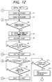
- Fig. 12 is a flowchart showing processes by the control unit 4-1 according to the embodiment 1.
- step S1 the board 901 as a processing target is received.
- step S2 the board 901 is processed by the processing device 5-1.
- step S3 in the control unit 4-2 on the downstream side, a check is made to see if the "transportable" signal has been set in address "B070H” in the common memory 204. If YES, the processing routine advances from step S3 to step S4 and the sampling data regarding the board during the processing or after completion of the processing is written into addresses "W012H" to "W015H” in the common memory 204. The processing is finished.
- the board ID of the board 901 to be delivered is written into addresses "W000H” to "W003H"
- the sheet processing quality information is stored into addresses "W00AH” to "W011H”
- the board kind information is stored into addresses "B030H” to "B035H”.
- step S5 A transporting motor of the transport device 6-1 is driven and the transportation of the board 901 is started.
- step S7 follows.
- the "delivery" signal in address "B011H" in the common memory 204 is set, thereby informing the control unit on the downstream side of a fact that the delivery of the board has been completed.
- step S8 the "acceptance" signal is set by the control unit on the downstream side.
- step S10 follows.
- the "delivery” signal set in step S7 is reset.
- Step S11 follows and a check is made to see if a preparation for reception of the next board 901 to be processed has been completed. If YES, step S12 follows and the "transportable" signal is set, thereby informing the control unit on the upstream side of a fact of the completion of the preparation.
- the processes from step S1 are repetitively executed.
- Fig. 13 is a flowchart showing processes by the control unit 4-2 locating on the downstream side of the control unit 4-1.
- step S21 a check is made to see if the preparation for reception of the board 901 has been completed. If YES, step S22 follows and the "transportable" signal (bit in address "B070H") is set, thereby informing the control unit 4-1 on the upstream side of a fact of the completion of the preparation. In the control unit 4-1, thus, the processing routine advances from step S3 to step S4 in Fig. 12.
- step S24 follows. A check is made by the sensor 903 in step S24 to see if the board 901 has reached.
- step S25 follows.
- the board ID (W00H to W003H) and the board kind information (B030H to B035H) stored in the common memory 204 are fetched.
- step S26 follows and the "acceptance" signal (bit in address "B061H") is set, thereby informing the control unit 4-1 of a fact that the conveyance has been completed.
- the processing routine in the control unit 4-1 advances from step S8 in Fig. 12 mentioned above to step S9.
- step S27 the "delivery” signal (bit in address “B061H") is reset.
- step S28 the "acceptance” signal in address “B061H” and the “transportable” signal in address “B070H” is reset.
- step S29 follows and the conveyed board is processed. Subsequent processes are similar to those in step S3 and subsequent steps in Fig. 12 mentioned above.
- Fig. 14 is a flowchart showing processes by the line controller 1 of the embodiment 1.
- the line controller 1 reads out the data from the common memory 204 of the control unit which is processing the board 901 and samples the read-out data at a predetermined sampling timing (steps S31 and S32). When the timing is not the sampling timing, the processing routine advances from step S31 to step S33. A check is made to see if the "delivery" signal (bit in address "BXX1H”: XX can be set to any one of "01", “06", “0B”, "10", "15”, and the like) of the control unit which is processing the board has been set.
- step S34 follows and the board ID (W00H to W003H), processing quality information (W00AH to W014H), and board kind information (B030H to B035H) are fetched.
- step S35 follows and the "reading-completion" signal (bit in address "B411H") is set.
- Step S36 follows and a check is made to see if the "delivery" signal of the control unit (for instance, control unit 4-1) as a target is OFF. If NO, step S38 follows and a check is made to see if the timing is the sampling timing in a manner similar to steps S31 and S32. When the sampling timing comes, step S39 follows and the data from the control unit which is processing the board is collected. When the "delivery" signal is reset in step S36, step S37 follows and the "reading-completion" signal (bit in address "B411H”) is reset, thereby notifying each control unit of a fact that the reading operation of various data of the common memory 204 has been completed. Thus, for example, as shown in the flowchart of Fig. 12, the processing routine advances from step S9 to step S10 and the "delivery" signal of the control unit as a target is reset.
- a selecting and housing processes when a defect occurs in the step (for example, inspecting step or the like) during the processing in the line will now be described.
- the quality information of the relevant board is rewritten to "NG" (for example, the board information on the head side is set to "B034H” and the board information on the rear side is set to "B035H", thereby rewriting).
- the invention can similarly cope with such a case by writing the quality information of each board into the relevant area in addresses "B036H” to "B03FH".
- the information regarding the quality of the board which is generated in the line as mentioned above is stored as board information in the control unit of each station, the board and the board information are tracked, and the processes are sequentially executed. In the final step, on the basis of the board ID, board information, and the like of the board which was tracked, a good product and a defective product of the boards are discriminated and they can be enclosed into different cassettes or the like.
- the information stored in the memory including those information effectively functions with respect to the management for ISO9000 or ISO14000.
- the line controller 1 since the same contents as those in each control unit 4 have been also stored in the common memory, it is also possible to easily perform the management regarding ISO9000 or ISO14000.
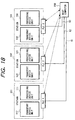
- Fig. 15 is a diagram showing a construction of a manufacturing line system according to the second embodiment of the invention. Portions common to those in the foregoing first embodiment are designated by the same reference numerals and their descriptions are omitted.
- reference numeral 7 denotes a cassette enclosing a plurality of boards.
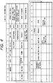
- the cassette 7 has a readable/writable ID tag 8 in which information shown in Fig. 16 has been stored.
- the ID tag 8 has "cassette ID”, "cassette empty/mounting classification” indicating whether the cassette is empty or a board has been mounted, "product lot No.”, "lot division classification”, “product kind code”, “completed process number”, “next process number”, “date of process”, “time of delivery from process”, and the like. Further, in the second embodiment, assuming that every two boards are taken out, each board ID and the information indicative of "OK” or "NG” of the boards A and B have been stored.
- a tracking control method in a manufacturing line in the second embodiment of the invention in a manufacturing processing line in which processing devices are connected by a network, when the board is delivered out by a board inserting station (corresponding to the station of the control unit 4-1) at the line head, namely, when the board is delivered to the station to be processed by the control unit 4-2 existing on the downstream side and is processed, it is confirmed that the "transportable" signal from the control unit 4-2 on the downstream side has been set.
- the information such as a board ID and the like stored in the ID tag 8 attached to the cassette 7, namely, the individual board ID, board information, and the like of every enclosing stage are read and stored into the common memory 204. After that, the board is delivered to the control unit 4-2 on the downstream side.
- the control unit 4-2 on the downstream side reads out the tracking information about the relevant board from a specific area in the common memory 204 at the timing for transportation mentioned above, fetches the read-out tracking information into a register (RAM) of the CPU of the control unit 4-2, and manages it. After completion of the process by the control of the control unit 4-2, the "transportable" signal from the control unit on the downstream side is examined. If "transportable”, the processed board is delivered to the step on the downstream side. Prior to the delivery of the board, the tracking information regarding the board to be delivered is set into a predetermined area in the common memory 204. On the basis of the information on the ID tag 8 attached to the cassette 7, an interlock and signal transmission and reception among the control units (stations) are executed by using the network 3.
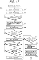
- Fig. 17 is a flowchart showing processes in the control unit 4-1 according to the second embodiment of the invention.
- step S43 when the "transportable" signal of the control unit on the downstream side is received, the ID tag information attached to the cassette 7 is read and the board information is stored into a specific area in the common memory 204.
- the individual board ID of every enclosing stage of the cassette 7 and the board information are stored into specific addresses in the common memory 204.
- step S45 to S52 the processed board is delivered to the station on the downstream side as shown in steps S5 to S12 in Fig. 12 mentioned above.
- step S53 when the board which was finally processed is transported to the station 10-n, the board quality is discriminated with reference to the board information stored in a predetermined address in the common memory 204. On the basis of the discrimination result, the board information is written into the ID tag of the cassette in step S54.
- the processes in steps S53 and S54 described here are executed by the control unit 4-n.
- the cassette 7 is set to another line and even when the board is processed in this line, the board information in the preceding line can be referred, so that the board can be transported and processed while tacking among a plurality of independent lines.
- the object of the invention is also accomplished by supplying a storing medium in which program codes of software to realize the functions of the foregoing embodiments have been recorded to a system or apparatus and by reading out and executing the program codes stored in the storing medium by a computer (or CPU or MPU) of the system or apparatus.
- the program codes themselves read out from the storing medium realize the functions of the embodiments mentioned above and the storing medium in which the program codes have been stored constructs the present invention.
- a storing medium to supply the program codes for example, it is also possible to use any one of a floppy disk, a hard disk, an optical disk, a magnetooptic disk, a CD-ROM, a CD-R, a magnetic tape, a non-volatile memory card, an ROM, and the like.
- the synchronization among the control units connected to the processing devices can be established by using the common memories.
- a line system in which control units each of which is connected to a processing device of a work are connected through a network has a memory which has data for processing the work by the processing device and which is provided for each control unit and makes the contents in the memories provided for the control units coincide.
Landscapes
- Engineering & Computer Science (AREA)
- General Engineering & Computer Science (AREA)
- Manufacturing & Machinery (AREA)
- Quality & Reliability (AREA)
- Physics & Mathematics (AREA)
- General Physics & Mathematics (AREA)
- Automation & Control Theory (AREA)
- General Factory Administration (AREA)
- Control By Computers (AREA)
- Automatic Assembly (AREA)
- Multi-Process Working Machines And Systems (AREA)
- Programmable Controllers (AREA)
Applications Claiming Priority (6)
| Application Number | Priority Date | Filing Date | Title |
|---|---|---|---|
| JP11628296 | 1996-05-10 | ||
| JP11628296 | 1996-05-10 | ||
| JP116282/96 | 1996-05-10 | ||
| JP9411097 | 1997-04-11 | ||
| JP9094110A JPH1039906A (ja) | 1996-05-10 | 1997-04-11 | ラインの制御方法とその装置及びラインシステム |
| JP94110/97 | 1997-04-11 |
Publications (2)
| Publication Number | Publication Date |
|---|---|
| EP0807875A1 true EP0807875A1 (fr) | 1997-11-19 |
| EP0807875B1 EP0807875B1 (fr) | 2002-11-13 |
Family
ID=26435424
Family Applications (1)
| Application Number | Title | Priority Date | Filing Date |
|---|---|---|---|
| EP97107679A Expired - Lifetime EP0807875B1 (fr) | 1996-05-10 | 1997-05-09 | Méthode et dispostif de commande d'une ligne de fabrication |
Country Status (4)
| Country | Link |
|---|---|
| US (1) | US6092001A (fr) |
| EP (1) | EP0807875B1 (fr) |
| JP (1) | JPH1039906A (fr) |
| DE (1) | DE69716996T2 (fr) |
Cited By (3)
| Publication number | Priority date | Publication date | Assignee | Title |
|---|---|---|---|---|
| FR2777369A1 (fr) * | 1997-12-31 | 1999-10-15 | Sloan Valve Co | Carte electronique de commande, notamment pour la commande d'appareils sanitaires |
| FR2813405A1 (fr) * | 2000-08-29 | 2002-03-01 | Schneider Automation Gmbh | Systeme de production |
| FR2819902A1 (fr) * | 2001-01-25 | 2002-07-26 | Joseph Valenza | Gestion et reconstitution electronique de lots |
Families Citing this family (8)
| Publication number | Priority date | Publication date | Assignee | Title |
|---|---|---|---|---|
| JP3548000B2 (ja) * | 1998-05-29 | 2004-07-28 | 矢崎総業株式会社 | ワイヤーハーネス製造装置及び該装置のタクトタイム制御方法 |
| US6745257B2 (en) * | 2001-01-04 | 2004-06-01 | International Business Machines Corporation | Method, system, and program for providing status in a multi-processing node system |
| US6836692B2 (en) * | 2001-08-09 | 2004-12-28 | Johnson & Johnson Vision Care, Inc. | System and method for intelligent lens transfer |
| US7904182B2 (en) * | 2005-06-08 | 2011-03-08 | Brooks Automation, Inc. | Scalable motion control system |
| JP4327181B2 (ja) * | 2006-07-27 | 2009-09-09 | 本田技研工業株式会社 | 部品製造管理システム及びその方法 |
| US7809458B2 (en) * | 2008-03-31 | 2010-10-05 | Honda Motor Co., Ltd. | Process control system with ability to exchange data with production line machine controllers |
| JP7211022B2 (ja) * | 2018-11-07 | 2023-01-24 | セイコーエプソン株式会社 | ウェブ製造装置およびシート製造装置 |
| JP7614941B2 (ja) | 2021-05-13 | 2025-01-16 | キヤノン株式会社 | モータ制御システムおよびモータ制御システムの制御方法 |
Citations (4)
| Publication number | Priority date | Publication date | Assignee | Title |
|---|---|---|---|---|
| GB2073460A (en) * | 1980-03-27 | 1981-10-14 | Willemin Machines Sa | Control system for a machine or for an installation |
| EP0156921A1 (fr) * | 1983-09-16 | 1985-10-09 | Fanuc Ltd. | Dispositif de commande numerique |
| EP0620512A1 (fr) * | 1992-10-26 | 1994-10-19 | Fanuc Ltd. | Controleur numerique |
| JPH07271424A (ja) * | 1994-03-29 | 1995-10-20 | Mazda Motor Corp | 生産設備制御装置 |
Family Cites Families (4)
| Publication number | Priority date | Publication date | Assignee | Title |
|---|---|---|---|---|
| US5150288A (en) * | 1989-12-18 | 1992-09-22 | Honda Giken Kogyo Kabushiki Kaisha | Production management system and method of transmitting data |
| JPH06139251A (ja) * | 1992-10-28 | 1994-05-20 | Pfu Ltd | 混流生産システム |
| US5555504A (en) * | 1994-06-10 | 1996-09-10 | Johnson & Johnson Vision Products, Inc. | Production line tracking and quality control system |
| US5551001A (en) * | 1994-06-29 | 1996-08-27 | Exponential Technology, Inc. | Master-slave cache system for instruction and data cache memories |
-
1997
- 1997-04-11 JP JP9094110A patent/JPH1039906A/ja not_active Withdrawn
- 1997-05-06 US US08/851,709 patent/US6092001A/en not_active Expired - Lifetime
- 1997-05-09 EP EP97107679A patent/EP0807875B1/fr not_active Expired - Lifetime
- 1997-05-09 DE DE69716996T patent/DE69716996T2/de not_active Expired - Lifetime
Patent Citations (4)
| Publication number | Priority date | Publication date | Assignee | Title |
|---|---|---|---|---|
| GB2073460A (en) * | 1980-03-27 | 1981-10-14 | Willemin Machines Sa | Control system for a machine or for an installation |
| EP0156921A1 (fr) * | 1983-09-16 | 1985-10-09 | Fanuc Ltd. | Dispositif de commande numerique |
| EP0620512A1 (fr) * | 1992-10-26 | 1994-10-19 | Fanuc Ltd. | Controleur numerique |
| JPH07271424A (ja) * | 1994-03-29 | 1995-10-20 | Mazda Motor Corp | 生産設備制御装置 |
Non-Patent Citations (3)
| Title |
|---|
| DATABASE WPI Derwent World Patents Index; AN 96013823, XP002037088 * |
| OCCELLO M. ET AL.: "A new Approach for Process Control", PROCEEDINGS ON COMPUTERS IN DESIGN, MANUFACTURING, AND PRODUCTION, 24 May 1993 (1993-05-24), PARIS-EVRY, FRANCE, pages 487 - 492, XP000463904 * |
| WECK M ET AL: "UNIVERSELLE ABLAUFSTEUERUNG FUER DIE FLEXIBLE FERTIGUNG", VDI Z, vol. 133, no. 3, 1 March 1991 (1991-03-01), pages 50, 53 - 56, XP000219808 * |
Cited By (3)
| Publication number | Priority date | Publication date | Assignee | Title |
|---|---|---|---|---|
| FR2777369A1 (fr) * | 1997-12-31 | 1999-10-15 | Sloan Valve Co | Carte electronique de commande, notamment pour la commande d'appareils sanitaires |
| FR2813405A1 (fr) * | 2000-08-29 | 2002-03-01 | Schneider Automation Gmbh | Systeme de production |
| FR2819902A1 (fr) * | 2001-01-25 | 2002-07-26 | Joseph Valenza | Gestion et reconstitution electronique de lots |
Also Published As
| Publication number | Publication date |
|---|---|
| EP0807875B1 (fr) | 2002-11-13 |
| US6092001A (en) | 2000-07-18 |
| JPH1039906A (ja) | 1998-02-13 |
| DE69716996D1 (de) | 2002-12-19 |
| DE69716996T2 (de) | 2003-04-10 |
Similar Documents
| Publication | Publication Date | Title |
|---|---|---|
| EP0807875B1 (fr) | Méthode et dispostif de commande d'une ligne de fabrication | |
| US5592400A (en) | Card issue system | |
| EP0218979A2 (fr) | Système de mise au point d'un programme de calculateur | |
| US5500797A (en) | Device for making use of information related to the breakdown detected by one or more central units of an aircraft | |
| US7380023B2 (en) | Vehicular communication device exchanging reception and transmission with external tool | |
| JPH03116395A (ja) | 自動販売機データ収集システム | |
| US20030100374A1 (en) | Mobile electronic information apparatus | |
| US5166928A (en) | Communication system comprising a communication line monitor for monitoring a communication line | |
| JPH11184513A (ja) | 制御システム及びその通信方法 | |
| GB2111735A (en) | Data transmission and processing systems | |
| JPH04283058A (ja) | 作業指示システム | |
| JPH0572329A (ja) | 個体識別装置 | |
| JP3010204B2 (ja) | 生産管理装置 | |
| JP2830380B2 (ja) | 識別システム及び物品識別方法 | |
| JP2735448B2 (ja) | Idカード及びそれを用いた半導体製造システム | |
| JPH11161336A (ja) | エンコーダ | |
| JPH06134656A (ja) | 生産指示装置 | |
| EP0308043A2 (fr) | Appareil et procédé pour le suivi et l'identification d'assemblage de circuits imprimés | |
| JP3297076B2 (ja) | 並列実行型プログラマブルコントローラシステムのプログラム管理方法 | |
| JP3521601B2 (ja) | データ伝送装置及びidシステム | |
| SU1473744A1 (ru) | Система дл контрол инкубаторов | |
| JPH067567B2 (ja) | 分散型作業進行管理方法 | |
| JP2003117742A (ja) | 組立生産システム | |
| JP4433492B2 (ja) | プログラマブルコントローラとの間のデータ授受方式 | |
| JPH07314296A (ja) | 生産管理装置及び製造設備制御装置 |
Legal Events
| Date | Code | Title | Description |
|---|---|---|---|
| PUAI | Public reference made under article 153(3) epc to a published international application that has entered the european phase |
Free format text: ORIGINAL CODE: 0009012 |
|
| AK | Designated contracting states |
Kind code of ref document: A1 Designated state(s): DE FR GB NL |
|
| 17P | Request for examination filed |
Effective date: 19980406 |
|
| 17Q | First examination report despatched |
Effective date: 19991216 |
|
| GRAG | Despatch of communication of intention to grant |
Free format text: ORIGINAL CODE: EPIDOS AGRA |
|
| GRAG | Despatch of communication of intention to grant |
Free format text: ORIGINAL CODE: EPIDOS AGRA |
|
| GRAH | Despatch of communication of intention to grant a patent |
Free format text: ORIGINAL CODE: EPIDOS IGRA |
|
| GRAH | Despatch of communication of intention to grant a patent |
Free format text: ORIGINAL CODE: EPIDOS IGRA |
|
| GRAA | (expected) grant |
Free format text: ORIGINAL CODE: 0009210 |
|
| AK | Designated contracting states |
Kind code of ref document: B1 Designated state(s): DE FR GB NL |
|
| REG | Reference to a national code |
Ref country code: GB Ref legal event code: FG4D |
|
| REF | Corresponds to: |
Ref document number: 69716996 Country of ref document: DE Date of ref document: 20021219 |
|
| ET | Fr: translation filed | ||
| PLBE | No opposition filed within time limit |
Free format text: ORIGINAL CODE: 0009261 |
|
| STAA | Information on the status of an ep patent application or granted ep patent |
Free format text: STATUS: NO OPPOSITION FILED WITHIN TIME LIMIT |
|
| 26N | No opposition filed |
Effective date: 20030814 |
|
| PGFP | Annual fee paid to national office [announced via postgrant information from national office to epo] |
Ref country code: NL Payment date: 20070515 Year of fee payment: 11 |
|
| PG25 | Lapsed in a contracting state [announced via postgrant information from national office to epo] |
Ref country code: NL Free format text: LAPSE BECAUSE OF NON-PAYMENT OF DUE FEES Effective date: 20081201 |
|
| REG | Reference to a national code |
Ref country code: FR Ref legal event code: PLFP Year of fee payment: 19 |
|
| PGFP | Annual fee paid to national office [announced via postgrant information from national office to epo] |
Ref country code: DE Payment date: 20150531 Year of fee payment: 19 Ref country code: GB Payment date: 20150528 Year of fee payment: 19 |
|
| PGFP | Annual fee paid to national office [announced via postgrant information from national office to epo] |
Ref country code: FR Payment date: 20150527 Year of fee payment: 19 |
|
| REG | Reference to a national code |
Ref country code: DE Ref legal event code: R119 Ref document number: 69716996 Country of ref document: DE |
|
| GBPC | Gb: european patent ceased through non-payment of renewal fee |
Effective date: 20160509 |
|
| REG | Reference to a national code |
Ref country code: FR Ref legal event code: ST Effective date: 20170131 |
|
| PG25 | Lapsed in a contracting state [announced via postgrant information from national office to epo] |
Ref country code: FR Free format text: LAPSE BECAUSE OF NON-PAYMENT OF DUE FEES Effective date: 20160531 Ref country code: DE Free format text: LAPSE BECAUSE OF NON-PAYMENT OF DUE FEES Effective date: 20161201 |
|
| PG25 | Lapsed in a contracting state [announced via postgrant information from national office to epo] |
Ref country code: GB Free format text: LAPSE BECAUSE OF NON-PAYMENT OF DUE FEES Effective date: 20160509 |