EP0807933A1 - Dispositif de chargement de cassette - Google Patents
Dispositif de chargement de cassette Download PDFInfo
- Publication number
- EP0807933A1 EP0807933A1 EP97303373A EP97303373A EP0807933A1 EP 0807933 A1 EP0807933 A1 EP 0807933A1 EP 97303373 A EP97303373 A EP 97303373A EP 97303373 A EP97303373 A EP 97303373A EP 0807933 A1 EP0807933 A1 EP 0807933A1
- Authority
- EP
- European Patent Office
- Prior art keywords
- cassette
- holder
- cassette holder
- gear
- magnetic tape
- Prior art date
- Legal status (The legal status is an assumption and is not a legal conclusion. Google has not performed a legal analysis and makes no representation as to the accuracy of the status listed.)
- Withdrawn
Links
- 238000001514 detection method Methods 0.000 claims abstract description 17
- 230000008878 coupling Effects 0.000 claims description 52
- 238000010168 coupling process Methods 0.000 claims description 52
- 238000005859 coupling reaction Methods 0.000 claims description 52
- 230000008859 change Effects 0.000 abstract description 42
- 238000003780 insertion Methods 0.000 description 27
- 230000037431 insertion Effects 0.000 description 27
- 230000003287 optical effect Effects 0.000 description 22
- 230000007246 mechanism Effects 0.000 description 9
- 230000001105 regulatory effect Effects 0.000 description 7
- 230000000994 depressogenic effect Effects 0.000 description 6
- 230000004044 response Effects 0.000 description 6
- 238000005096 rolling process Methods 0.000 description 6
- 230000007257 malfunction Effects 0.000 description 5
- 239000011435 rock Substances 0.000 description 5
- 238000012840 feeding operation Methods 0.000 description 3
- 238000000034 method Methods 0.000 description 3
- 230000000593 degrading effect Effects 0.000 description 2
- 238000004804 winding Methods 0.000 description 2
- 230000009471 action Effects 0.000 description 1
- 230000000694 effects Effects 0.000 description 1
Images









Classifications
-
- G—PHYSICS
- G11—INFORMATION STORAGE
- G11B—INFORMATION STORAGE BASED ON RELATIVE MOVEMENT BETWEEN RECORD CARRIER AND TRANSDUCER
- G11B25/00—Apparatus characterised by the shape of record carrier employed but not specific to the method of recording or reproducing, e.g. dictating apparatus; Combinations of such apparatus
- G11B25/06—Apparatus characterised by the shape of record carrier employed but not specific to the method of recording or reproducing, e.g. dictating apparatus; Combinations of such apparatus using web-form record carriers, e.g. tape
- G11B25/066—Apparatus characterised by the shape of record carrier employed but not specific to the method of recording or reproducing, e.g. dictating apparatus; Combinations of such apparatus using web-form record carriers, e.g. tape adapted for use with containers of different sizes or configurations; adaptor devices therefor
Definitions
- the present invention relates to a cassette loading device for loading a magnetic tape cassette selected from multiple types of magnetic tape cassettes different in outside dimensions from one another.
- VTR magnetic recording/reproducing apparatuses
- various standards i.e., magnetic recording methods
- various VTRs based on different standards tend to compete for market share.
- various kinds of magnetic tape cassettes to be referred to hereinbelow as cassette
- various kinds of cassettes based on the same standard but different in cassette size (outside diameter, reel distance) are put onto the market.
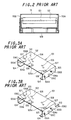
- Figs.1A and 1B are plan views showing a conventional cassette loading device 100 incorporated in the compatible VTR;
- Fig.2 is a front view of Fig.1;
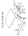
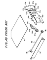
- Figs.3A, 3B, 4A, 4B and 5 are perspective views showing essential parts.
- Cassette loading device 100 has a cassette holder 101, which is integrally formed of a top portion 102, left and right side portions 103, and L-cassette guiding pieces 104 for guiding the undersurface of L-cassette LC.
- L-cassette guiding piece 104 has an integrally formed S-cassette guiding piece 105 at its distal end.
- L-cassette guiding piece 104 has a stopper piece 104a which has been formed upright to bear the front part, with respect to the cassette's direction of movement, of L-cassette LC.
- S-cassette guiding piece 105 has a stopper piece 105a which has been formed upright to bear the front part, with respect to the cassette's direction of movement, of S-cassette SC.
- Each side portion 103 has 1st through 3rd slider axles 106A, 106B and 106C press fitted.
- Leaf springs 107 and 108 for pressing L-cassette and S-cassette, respectively are press fitted in top portion 102.
- an engaging boss 106D is provided on only the side portion 103 located on the right side in the figure.
- a mech-chassis 109 which supports cassette loading device 100, has a pair of right and left frames110A and 110B standing upright parallel to each other. Each frame 110A and 110B has integrally formed, inwardly bent flanges 110a on the upper edge thereof. A top plate 111 supported by these flanges 110a, is provided between frames 110A and 110B. Pivotally supported between frames 110A and 110B is a cassette port door 112 for opening and closing the port of cassette holder 101. Cassette port door 112 is biased toward the closed direction by an unillustrated door shutting spring.
- Frames 110A and 110B each have a 1st L-shaped guide slot 113a engaged with and guiding 1st slider axle 106A of cassette holder 101, and a 2nd L-shaped guide slot 113b engaged with and guiding 2nd slider axle 106B, whereby cassette holder 101 is supported so as to be able to slide along guide slots 113a and 113b. Further, frames 110A and 110B each have a rib-formed guide slot 113c which is engaged with 3rd slider axle 106C to guide the downward movement of cassette holder 101 when it moves downwards (to be described later).
- Drive arms 114A and 114B are pivoted on the inner sides of respective frames 110A and 110B so that they are free to rock back and forth.
- Drive arms 114A and 114B each have a semicircular gear 114a formed coaxially with the support axle thereof.
- Rotationally supported between left and right frames 110A and 110B is a link shaft 115.
- This link shaft 115 has timing gears 116, 116 attached at both ends in phase.
- Timing gears 116, 116 are in mesh with semicircular gears 114a of drive arms 114A and 114B, respectively, so that both drive arms 114A and 114B will sway integrally.
- Drive arms 114A and 114B have respective slots 114b, 114b, which extend along the length thereof. This slot 114b is engaged with 1st slider axle 106A which also fits through 1st guide slot 113a.
- Left drive arm 114B has another semicircular gear 114c which is formed coaxially with the support axle of drive arm 114B.
- Drive arms 114A and 114B each have a cassette pressing spring 114d which urges 1st slider axle 106A engaging slot 114b, in such a direction as to press the distal end of drive arm 114A or 114B toward the chassis interior (in the clockwise direction in Figs.4A and 4B, and in the counterclockwise direction in Fig.5).
- the outer side of left frame 110B has 4th through 6th slider axles 117A, 117B and 117C press fitted thereon.
- a double-acting plate 118 is provided on the outer side of left frame 110B.
- Double-acting plate 118 has guide slots 118a, 118b and 118c which are engaged with 4th through 6th slider axles 117A to 117C, respectively, so that double-acting plate 118 will be able to move back and forth relative to frame 110B in the cassette's direction of movement.
- Double-acting plate 118 has a rack gear 118d meshed with semicircular gear 114c of drive arm 114B so that double-acting plate 118 will move linearly in the cassette's direction of insertion as drive arm 114B moves swayingly.
- driving plate 119 Provided on the outer side of double-acting plate 118 is a driving plate 119, which has guide slots 119a, 119b and 119c engaged with 4th through 6th slider axles 117A to 117C, respectively.
- driving plate 119 will be able to move back and fourth relative to frame 110B in the cassette's direction of movement.
- a double-acting spring 120 a tension spring is provided between double-acting plate 118 and driving plate 119 at their inner ends thereof.
- Driving plate 119 has a rack gear 119e which, similarly to rack gear 118d, is in mesh with semicircular gear 114c and another rack gear 119f which receives the driving force from an unillustrated driver motor for loading.
- Rack gear 118d is formed with such a length as to be in mesh with semicircular gear 114c from the beginning of the rocking movement of drive arm 114B to the end.
- Rack gear 119e is formed with such a length that it will not be in mesh at the beginning of the rocking movement of drive arm 114B but will become engaged with the other semicircular gear 114c of the drive arm 114B in the course of rocking movement of the arm to the end.
- mech-chassis 109 has a light emitter 121.
- a light-receiving sensor 122 that receives the sensor light from light emitter 121 and a shutter 123 as shown in Fig.4B.
- Shutter 123 is provided so as to move up and down along the inner side of frame 110A and is urged upward by means of a spring 124.
- Shutter 123 has a slanting surface 123a in the upper part thereof which is engaged with engaging boss 106D of cassette holder 101.
- shutter 123 is formed with an opening 123b which allows completion of the optical path from light emitter 121 to light-receiving sensor 122 only when engaging boss 106D becomes engaged with the shutter forcibly moving it downwards.
- the sensing device consisting of light emitter 121 and light-receiving sensor 122 detects the timing of starting the cassette in-pulling operation (to be described next), and in addition, performs BOT detection (detection of the beginning of taking up the magnetic tape accommodated in cassette LC or SC) and EOT detection (detection of the end of taking up the magnetic tape accommodated in cassette LC or SC). Due to the tape winding direction of the cassette, the sensing device provided on the right of the frame in the figure is adapted to detect BOT, whereas the sensing device on the left of the frame is adapted to detects EOT.
- an L-cassette LC is inserted from an unillustrated inserting port so that it is placed on L-cassette guiding piece 104 of cassette holder 101.
- a further insertion of the L-cassette LC into the chassis interior makes it abut stopper piece 104a, on its inner side edge with respect to the moving direction of LC-cassette LC.
- the L-cassette LC is pressed against L-cassette guiding piece 104 from above by leaf springs 107, so that it will be stably held inside cassette holder 101.
- 1st and 2nd slider axles 106A and 106B will reach the vertically slotted portions of 1st and 2nd guide slots 113a and 113b, and 3rd slider axle 106C will become engaged with rib-formed guide slot 113c.
- an unillustrated cassette size detecting lever provided on mech-chassis 109 detects the inserted cassette as to be an L-cassette LC, to thereby drive an unillustrated reel table shifting mechanism. In this way, unillustrated reel tables are adjusted so that the distance between the reel tables will match the reel distance of L-cassette LC.
- cassette holder 101 When cassette holder 101 has moved down to its terminal position, the L-cassette LC is placed on four cassette stays 125 (see Fig.6F) planted on mech-chassis 109. In this condition, cassette holder 101 is pressed downwards by means of cassette pressing springs 114d provided for drive arms 114A and 114B. Therefore, the L-cassette LC becomes pressed in contact with cassette stays 125 with its bottom slightly spaced away from L-cassette guiding piece 104.
- the S-cassette SC is inserted from an unillustrated inserting port so that it is placed on S-cassette guiding piece 105 of cassette holder 101.
- a further insertion of the S-cassette SC into the chassis interior makes it abut stopper piece 105a, on its inner side edge with respect to the moving direction of SC-cassette SC.
- the S-cassette SC is pressed against S-cassette guiding piece 105 from above by leaf springs 108, so that it will be stably held inside cassette holder 101.
- the point for starting the in-pulling operation of a cassette is set up in the following manner.
- the cassette in-pulling operation is activated (the cassette loading switch is turned on so that an unillustrated driving motor starts to cause the driving plate 119 to perform pull-in action) if the cassette is pushed in to a predetermined position sd in order to prevent the fingers from being caught between the cassette inserting port and the cassette and injured.
- the two kinds, small and large types of cassettes LC and SC handled by cassette loading device 100 must be positioned so that the mouth positions of cassettes LC and SC after they have been loaded will coincide with each other.
- the mouth position means the reference position on the forward side in the loading direction of cassette LC or SC, which serves as the reference point for drawing out the magnetic tape.
- the rear ends, with respect to the loading direction, of the different types of cassettes are positioned with a difference D, as shown in Fig.8, and it was impossible to avoid this.
- the timing for the cassette in-pulling operation was set up so as to be suitable for S-cassette SC.
- the cassette in-pulling operation is started when the rear side with respect to the cassette loading direction has reached the aforementioned predetermined position sd (see Figs.7B, 7D).
- the projected amount of L-cassette LD (the distance projected from the VTR front panel) becomes too large.
- each cassette LC and SC abuts stopper pieces 104a and 105a, the projected amounts of cassettes LC and SC from the VTR front panel FP differ, resulting in ineptness of cassette insertion and degrading the handling performance.
- the projected amount sD (see Figs.7A and 7C) of S-cassette SC from the VTR front panel FP when it abuts stopper piece 105a, is set optimally (at about 10 mm; this might change depending upon the size of the S-cassette SC and the aforementioned predetermined position sd)
- the operation with L-cassette LC projected out to such a large degree is awkward and clumsy looking, degrading the handling performance.
- the present invention offers the following means to solve the problems described above.
- a cassette loading device for handling plural kinds of magnetic tape cassettes different in outside dimensions, comprises: an inputting means which moves a magnetic tape cassette in linkage with a pushing operation of the cassette by the operator up to a position where the cassette in-pulling operation starts; and a plurality of cassette holders in conformity with the number of the plural kinds of magnetic tape cassettes to be handled, and is characterized in that the cassette holders are arranged such that one cassette holder is fitted into the other holder so as to slide in the cassette's direction of movement relative to the other.
- a cassette loading device having the above first feature is characterized in that the inputting means moves the other cassette holder with a different amount of stroke from the pushed amount of stroke for the magnetic tape cassette inserted in the one cassette holder.
- a cassette loading device having the above second feature, is characterized in that the inputting means comprises: a coupling gear which is composed of a pair of gear parts coaxially arranged with respect to each other and is rotatably attached to the one cassette holder; a first rack gear which is provided so as to be unable to move in the cassette's direction of movement and is meshed with one gear part of the coupling gear; and a second rack gear which is fixed to the other cassette holder and meshed with the other gear part of the coupling gear.
- a cassette loading device for handling plural kinds of magnetic tape cassettes different in outside dimensions, comprises: an inputting means which moves a cassette holder into which magnetic tape cassettes different in outside dimensions are selectively inserted, in linkage with a pushing operation of the magnetic tape cassette by the operator, to a position where the cassette in-pulling operation starts; a functioning member which selectively operates in accordance with the movement of the magnetic tape cassette held in the cassette holder and in accordance with the outside dimensions thereof; and a changing means which changes a position where the cassette in-pulling operation starts in the moving direction of the cassette holder, in accordance with the operating state of the functioning member.
- a cassette loading device having the above fourth feature is characterized in that the functioning member is rotationally supported at a central portion across the length, and has on one end thereof, an engaging portion which selectively engages a magnetic tape cassette inserted into the cassette holder in accordance with the outside dimensions of the cassette, and on the other end thereof, a plurality of position designating portions which are provided corresponding to the outside dimensions of the magnetic tape cassettes and are spaced from each other with respect to the moving direction of the cassette holder, while the changing means selectively detects one position designating portion at the terminal end of the movement of the cassette and starts the cassette in-pulling operation at the time of the detection.
- a cassette loading device having the above fifth feature, is characterized in that the position designating portion comprises an opening formed in the functioning member and the changing means comprises a detector optically detecting the opening.
- a cassette loading device having the above fifth feature is characterized in that the position designating portion comprises a projection formed in the functioning member and the changing means comprises a detector detecting the projection by mechanical engagement with the projection.
- a cassette loading device having the above fourth feature is characterized in that a plurality of cassette holders are provided in conformity with the number of the plural kinds of magnetic tape cassettes to be handled and are arranged such that one cassette holder is fitted into the other holder so as to slide in the cassette's direction of movement relative to the other, and the inputting means moves the other cassette holder with a different amount of stroke from the pushed amount of stroke for the magnetic tape cassette inserted in the one cassette holder.
- cassette loading device having the above fifth feature is characterized in that a plurality of cassette holders are provided in conformity with the number of the plural kinds of magnetic tape cassettes to be handled and are arranged such that one cassette holder is fitted into the other holder so as to slide in the cassette's direction of movement relative to the other, and the inputting means moves the other cassette holder with a different amount of stroke from the pushed amount of stroke for the magnetic tape cassette inserted in the one cassette holder.
- cassette loading device having the above sixth feature is characterized in that a plurality of cassette holders are provided in conformity with the number of the plural kinds of magnetic tape cassettes to be handled and are arranged such that one cassette holder is fitted into the other holder so as to slide in the cassette's direction of movement relative to the other, and the inputting means moves the other cassette holder with a different amount of stroke from the pushed amount of stroke for the magnetic tape cassette inserted in the one cassette holder.
- a cassette loading device having the above seventh feature is characterized in that a plurality of cassette holders are provided in conformity with the number of the plural kinds of magnetic tape cassettes to be handled and are arranged such that one cassette holder is fitted into the other holder so as to slide in the cassette's direction of movement relative to the other, and the inputting means moves the other cassette holder with a different amount of stroke from the pushed amount of stroke for the magnetic tape cassette inserted in the one cassette holder.
- a cassette loading device having the above eighth feature is characterized in that the inputting means comprises: a coupling gear which is composed of a large-diametric gear part and a small-diametric gear part coaxially arranged with respect to each other and is rotatably attached to the one cassette holder; a first rack gear which is provided so as to be unable to move in the cassette's direction of movement and meshed with the large-diametric gear part; and a second rack gear which is fixed to the other cassette holder and meshed with the small-diametric gear part of the coupling gear.
- a cassette loading device having the above ninth feature is characterized in that the inputting means comprises: a coupling gear which is composed of a large-diametric gear part and a small-diametric gear part coaxially arranged with respect to each other and is rotatably attached to the one cassette holder; a first rack gear which is provided so as to be unable to move in the cassette's direction of movement and meshed with the large-diametric gear part; and a second rack gear which is fixed to the other cassette holder and meshed with the small-diametric gear part of the coupling gear.
- a cassette loading device having the above tenth feature is characterized in that the inputting means comprises: a coupling gear which is composed of a large-diametric gear part and a small-diametric gear part coaxially arranged with respect to each other and is rotatably attached to the one cassette holder; a first rack gear which is provided so as to be unable to move in the cassette's direction of movement and meshed with the large-diametric gear part; and a second rack gear which is fixed to the other cassette holder and meshed with the small-diametric gear part of the coupling gear.
- a cassette loading device having the above eleventh feature is characterized in that the inputting means comprises: a coupling gear which is composed of a large-diametric gear part and a small-diametric gear part coaxially arranged with respect to each other and is rotatably attached to the one cassette holder; a first rack gear which is provided so as to be unable to move in the cassette's direction of movement and meshed with the large-diametric gear part; and a second rack gear which is fixed to the other cassette holder and meshed with the small-diametric gear part of the coupling gear.
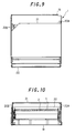
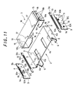
- a cassette loading device 1 comprises an L-cassette holder 2 and an S-cassette holder 3 as shown in Figs.9-13.
- S-cassette holder 3 is made to fit on L-cassette holder 2 in a slidable manner along the cassette's direction of movement.
- L-cassette holder 2 is integrally formed of a top portion 4, left and right side portions 5, and L-cassette guiding pieces 6 for guiding the undersurface of L-cassette LC.
- L-cassette guiding piece 6 has a stopper piece 6a which has been formed upright to bear the front part of L-cassette LC.
- Leaf springs 7 for pressing L-cassette are press fitted in top portion 4. The distance between left and right L-cassette guiding pieces 6 is set equal to or greater than the width of S-cassette SC.
- L-holder side plates 9 are fixed to bosses 8 with screws.
- a coupling gear 10 and a fixed rack guiding boss 11 are provided on the inner side of L-holder side plate 9.
- Coupling gear 10 is composed of two different-sized gears having different pitch circle diameters, a large-diametric gear part 10a and a small-diametric gear part 10b integrally formed concentrically, and is attached rotatably to L-holder side plate 9.
- 1st to 3rd slider axles 12A, 12B and 12C and a sensor engagement projection 9b are provided on the outer side of L-holder side plate 9 .
- a guide slot 9a extending horizontally is formed in L-holder side plate 9.
- sensor engagement projection 9b is provided only on one L-holder side plate (the left one in Fig.11) 9, while mech-chassis 19 has a cassette loading switch 31 (see Figs.14A-14C, Figs.15A-15C) which is engaged with this sensor engagement projection 9b.
- a fixed rack 13 is provided between side portion 5 and L-holder side plate 9.
- Fixed rack 13 has a first rack gear 13a meshing large-diametric gear part 10a, a guide slot 13b engaged with fixed rack guide boss 11 and a position regulating boss 13c.
- S-cassette holder 3 is composed of a top portion 14, left and right side portions 15 and S-cassette guiding pieces 16 for guiding the undersurface of S-cassette SC.
- S-cassette guiding piece 16 has a stopper piece 16a which has been formed upright to bear the front part of S-cassette SC.
- Leaf springs 17 for pressing S-cassette are press fitted in top portion 14.
- a movable rack 18 Fixed on the outer face of side portion 15 is a movable rack 18, which has a 2nd rack gear 18a and a sliding bosses 18b. Second rack gear 18a is meshed with small-diametric gear part 10b of coupling gear 10. Sliding bosses 18b engage with guide slot 9a of L-holder side plate 9.
- top portion 4 of L-cassette holder 2 are clearance holes 4a for leaf springs 17 on S-cassette holder 3.
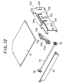
- Mech-chassis 19 which supports cassette loading device 1, has a pair of right and left frames 20A and 20B standing upright parallel to each other. Each frame 20A and 20B has integrally formed, inwardly bent flanges 20a on the upper edge thereof. A top plate 21 supported by these flanges 20a, is provided between frames 20A and 20B. Pivotally supported between frames 20A and 20B is a cassette port door 22 for opening and closing the port for both cassette holders 2 and 3. Cassette port door 22 is biased toward the closed direction by an unillustrated door shutting spring.
- Frames 20A and 20B each have a 1st L-shaped guide slot 23a engaged with and guiding the 1st slider axle 12A of L-cassette side plate 9, and a 2nd L-shaped guide slot 23b engaged with and guiding 2nd slider axle 12B, whereby L-cassette side plate 9 is supported so as to be able to slide along guide slots 23a and 23b.
- frames 20A and 20B each include: a rib-formed guide slot 23c which is engaged with 3rd slider axle 12C to guide the downward movement when both cassette holders 2 and 3 move downwards; and a guide slot 23d which guides position regulating boss 13c of fixed rack 13 in the vertical direction and inhibits the motion in the cassette's direction of movement.
- Drive arms 24A and 24B are pivoted on the inner sides of respective frames 20A and 20B so that they are free to rock back and forth.
- Drive arms 24A and 24B each have a semicircular gear 24a formed coaxially with the support axle thereof.
- Rotationally supported between left and right frames 20A and 20B is a link shaft 25.
- This link shaft 25 has timing gears 26, 26 attached at both ends in phase.
- Timing gears 26, 26 are in mesh with semicircular gears 24a of drive arms 24A and 24B, respectively, so that both drive arms 24A and 24B will rotate integrally.
- Drive arms 24A and 24B have respective slots 24b, 24b, which extend along the length thereof. This slot 24b is engaged with 1st slider axle 12A which also fits through 1st guide slot 23a.
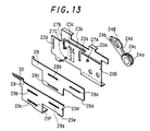
- Left drive arm 24B has another semicircular gear 24c which is formed coaxially with the support axle of drive arm 24B.
- Drive arms 24A and 24B each have a cassette pressing spring 24d which urges 1st slider axle 12A engaging slot 24b, in such a direction as to press the distal end of drive arm 24A or 24B toward the chassis interior (in the clockwise direction in Fig.12, and in the counterclockwise direction in Fig.13).
- the outer side of left frame 20B has 4th through 6th slider axles 27A, 27B and 27C press fitted thereon.
- a double-acting plate 28 is provided on the outer side of left frame 20B.
- Double-acting plate 28 has guide slots 28a, 28b and 28c which are engaged with 4th through 6th slider axles 27A to 27C, respectively, so that double-acting plate 28 will be able to move back and forth relative to frame 20B in the cassette's direction of insertion.
- Double-acting plate 28 has a rack gear 28d meshed with semicircular gear 24c of drive arm 24B so that double-acting plate 28 will move linearly in the cassette's direction of insertion as drive arm 24B moves swayingly.
- driving plate 29 Provided on the outer side of double-acting plate 28 is a driving plate 29, which has guide slots 29a, 29b and 29c engaged with 4th through 6th slider axles 27A to 27C, respectively.
- driving plate 29 will be able to move back and fourth relative to frame 20B in the cassette's direction of insertion.
- a double-acting spring 30, a tension spring is provided between double-acting plate 28 and driving plate 29 at their inner ends thereof.
- Driving plate 29 has a rack gear 29e which, similarly to rack gear 28d, is in mesh with semicircular gear 24c, and another rack gear 29f which receives the driving force from an unillustrated driver motor for loading.
- Rack gear 28d is formed with such a length as to be in mesh with semicircular gear 24c from the beginning of the rocking movement of drive arm 24B to the end.
- Rack gear 29e is formed with such a length that it will not be in mesh at the beginning of the rocking movement of drive arm 24B but will become engaged with semicircular gear 24c of drive arm 24B in the course of rocking movement of the arm to the end.
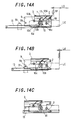
- cassette loading device 1 since fixed rack 13 is inhibited from moving in the cassette's direction of movement by guide slot 23d, when L-cassette holder 2 is moved, S-cassette holder 3 will also move through coupling gear 10 and fixed rack 13. In this case, S-cassette holder 3 undergoes extra movement compared to L-cassette holder 2, corresponding to the ratio of the pitch circle diameters of large-diametric gear part 10a and small-diametric gear part 10b.
- the horizontal conveyance starts from the inserted positions of L- and S-cassettes LC and SC (at the positions where cassettes LC and SC abut stopper pieces 6a and 16a, respectively). Since the L-cassette holder 2 is located at a more inward position relative to the chassis interior, it is possible to reduce the projected amount (designated at LD in Fig.14A) of L-cassette LC at its inserted position from the VTR front panel FP.
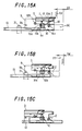
- the projected amount (designated at SD in Fig.15A) of S-cassette SC at its inserted position from the VTR front panel FP can be made coincident with the aforementioned projected amount LD.
- an L-cassette LC is inserted from an unillustrated inserting port so that it is placed on L-cassette guiding piece 6 of cassette holder 2.
- a further insertion of the L-cassette LC into the chassis interior makes it abut stopper piece 6a, on its inner side edge.
- the L-cassette LC is pressed against L-cassette guiding piece 6 from above by leaf springs 17, so that it will be stably held inside L-cassette holder 2.
- Movable rack 18 (S-cassette holder 3), which is placed on in mesh with coupling gear 10, also moves horizontally, as coupling gear 10 travels horizontally.
- movable rack 18 (S-cassette holder 3) meshed with small-diametric gear part 10b turned by the rolling of coupling gear 10, moves further toward the chassis interior as it rolls over small-diametric gear part 10b. Therefore, S-cassette holder 3 travels further, which is the distance in which movable rack 18 moves over the rolling small-diametric gear part 10b, than L-cassette holder 2.
- L-holder side plate 9 is guided with its 1st and 2nd slider axles 12A and 12B engaging 1st and 2nd guide slots 23a and 23b of frames 20A and 20B.
- drive arms 24A and 24B when 1st slider axles 12A move toward the chassis interior, drive arms 24A and 24B whose slots 24b are engaged with 1st slider axles 12A, swayingly move their distal ends toward the chassis interior (in the clockwise direction in Fig.12, and in the counterclockwise direction in Fig.13). Since drive arms 24A and 24B are coupled by link shaft 25, timing gears 26, 26 and semicircular gears 24a, they will sway in synchronism.
- double-acting plate 28 meshed with semicircular gear 24c moves slightly toward the chassis interior. During this, since driving plate 29 will not move, double-acting plate 28 will move whilst extending double-acting spring 30 provided between double-acting plate 28 and driving plate 29.
- drive arm 24B When double-acting plate 28 is moved toward the chassis interior by driving plate 29, drive arm 24B whose semicircular gear 24c is meshed with rack gear 28d of double-acting plate 28, sways in such a direction that the distal end thereof moves toward the chassis interior (in the counterclockwise direction in Fig.13) while drive arm 24A also sways in synchronism.
- 1st slider axles 12A, 12A engaging slots 24b and 24b of drive arms 24A and 24B move toward the chassis interior.
- L-cassette holder 2 moves together with the L-cassette LC toward the chassis interior.
- L-cassette holder 2 is guided by the engagement of 1st and 2nd slider axles 12A and 12B with 1st and 2nd guide slots 23a and 23b.
- an unillustrated cassette size detecting switch detects the inserted cassette as to be an L-cassette LC, to thereby drive an unillustrated reel table shifting mechanism.
- the reel tables are adjusted so that the distance between the reel tables will match the reel distance of L-cassette LC.
- L-cassette holder 2 will move downwards together with the L-cassette LC.
- fixed rack 13 moves downwards together with L-cassette holder 2 since position regulating bosses 13c are guided along guide slots 23d.
- the L-cassette LC which already has been pulled in to the lowest position of the in-pulling operation, is placed on four cassette stays (not shown) planted on mech-chassis 19. In this condition, drive arms 24A and 24B urged by cassette pressing springs 24d press 1st slider axles 12A downwards. Therefore, the L-cassette LC becomes pressed in contact with the aforementioned cassette stays with its bottom slightly spaced away from L-cassette guiding piece 6.
- FIG.15A an S-cassette SC is inserted from an unillustrated inserting port so that it is placed on S-cassette guiding piece 16 of cassette holder 3.
- a further insertion of the S-cassette SC into the chassis interior makes the inner side edge thereof abut stopper piece 16a of S-cassette guiding piece 16.
- the S-cassette SC is pressed against S-cassette guiding piece 16 from above by leaf springs 17, so that it will be stably held inside S-cassette holder 3.
- L-holder side plate 9 is guided with its 1st and 2nd slider axles 12A and 12B engaging 1st and 2nd guide slots 23a and 23b of frames 20A and 20B.
- drive arms 24A and 24B when 1st slider axles 12A move toward the chassis interior, drive arms 24A and 24B whose slots 24b are engaged with 1st slider axles 12A, swayingly move their distal ends toward the chassis interior (in the clockwise direction in Fig.12, and in the counterclockwise direction in Fig.13). Since drive arms 24A and 24B are coupled by link shaft 25, timing gears 26, 26 and semicircular gears 24a, they will sway in synchronism.
- double-acting plate 28 meshed with semicircular gear 24c moves slightly toward the chassis interior. During this, since driving plate 29 will not move, double-acting plate 28 will move whilst extending double-acting spring 30 provided between double-acting plate 28 and driving plate 29.
- drive arm 24B When double-acting plate 28 is moved toward the chassis interior by driving plate 29, drive arm 24B whose semicircular gear 24c is meshed with rack gear 28d of double-acting plate 28, sways in such a direction that the distal end thereof moves toward the chassis interior (in the counterclockwise direction in Fig.13) while drive arm 24A also sways in synchronism.
- 1st slider axles 12A, 12A engaging slots 24b and 24b of drive arms 24A and 24B move toward the chassis interior.
- S-cassette holder 3 moves together with the S-cassette SC toward the chassis interior.
- S-cassette holder 3 is guided by the engagement of 1st and 2nd slider axles 12A and 12B with 1st and 2nd guide slots 23a and 23b.
- an unillustrated cassette size detecting switch detects the inserted cassette as to be an S-cassette SC, to thereby drive an unillustrated reel table shifting mechanism.
- the reel tables are adjusted so that the distance between the reel tables will match the reel distance of S-cassette SC.
- the S-cassette SC which already has been pulled in to the lowest position of the in-pulling operation, is placed on four cassette stays (not shown) planted on mech-chassis 19. In this condition, drive arms 24A and 24B urged by cassette pressing springs 24d press 1st slider axles 12A downwards. Therefore, the S-cassette SC becomes pressed in contact with the aforementioned cassette stays with its bottom slightly spaced away from S-cassette guiding piece 16.
- 1st to 3rd slider axles 12A to 12C are provided for L-cassette holder 2 so as to drive it by means of drive arms 24A and 24B, these 1st to 3rd slider axles 12A to 12C may be provided in S-cassette holder 3.
- S-cassette holder 3 is arranged in such a manner as to enclose L-cassette holder 2, but it is also possible to make such an arrangement that L-cassette holder 2 encloses S-cassette holder 3.
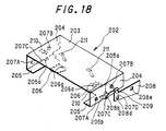
- a cassette loading device 201 has a cassette holder 202, which is integrally formed of a top portion 203, left and right side portions 204, and L-cassette guiding pieces 205 for guiding the undersurface of L-cassette LC.
- L-cassette guiding piece 205 has an integrally formed S-cassette guiding piece 206 at its distal end.
- L-cassette guiding piece 205 has a stopper piece 205a which has been formed upright to bear the front part, with respect to the cassette's direction of movement, of L-cassette LC.
- S-cassette guiding piece 206 has a stopper piece 206a which has been formed upright to bear the front part, with respect to the cassette's direction of movement, of S-cassette SC.
- the L-cassette guiding piece 205 on the right in Fig.18 has an opening 205b (see Fig.21) into which an aftermentioned timing change lever 208 is fitted.
- Each side portion 204 has 1st through 3rd slider axles 207A, 207B, 207C and a boss 207D press fitted.
- Boss 207D is provided on only the side portion 204 located on the right side in Fig.18.
- Timing change lever 208 is pivotally attached to boss 207D. Timing change lever 208 is supported at the central portion across its width by boss 207D.
- timing change lever 208 is bent so as to fit along the bottom surface of L-cassette guiding piece 205. Further, a distal end 208b of end portion 208a is bent upward so that it can be fitted through opening 205b of L-cassette guiding piece 205. Since opening 205b is provided in L-cassette guiding piece 205, distal end 208b will engage the bottom of the L-cassette LC only when an L-cassette LC is loaded to cassette holder 202, whereas it will not engage the bottom of the S-cassette SC when an S-cassette SC is loaded.
- Timing change lever 208 on the inner side with respect to the cassette's direction of insertion is formed in an L-shape and is positioned below side portion 204.
- This end portion 208c has a 1st opening 208d and a 2nd opening 208e.
- First and second openings 208d and 208e are arranged along the length of end portion 208c.
- Timing change lever 208 thus configured is urged by a spring 209 in such a direction that its distal end 208b projects from opening 205b (in clockwise direction in Figs.18 and 21).
- Leaf springs 210 and 211 for pressing L-cassette and S-cassette, respectively are press fitted in top portion 203.
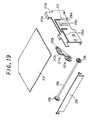
- a mech-chassis 212 which supports cassette loading device 201, has a pair of right and left frames 213A and 213B standing upright parallel to each other. Each frame 213A and 213B has integrally formed, inwardly bent flanges 213a on the upper edge thereof. A top plate 214 supported by these flanges 213a, is provided between frames 213A and 213B. Pivotally supported between frames 213A and 213B is a cassette port door 215 for opening and closing the port of cassette holder 202. Cassette port door 215 is biased toward the closed direction by an unillustrated door shutting spring.
- Frames 213A and 213B each have a 1st L-shaped guide slot 216a engaged with and guiding 1st slider axle 207A of cassette holder 202, and a 2nd L-shaped guide slot 216b engaged with and guiding 2nd slider axle 207B, whereby cassette holder 202 is supported so as to be able to slide along guide slots 216a and 216b. Further, frames 213A and 213B each have a rib-formed guide slot 216c which is engaged with 3rd slider axle 207C to guide the downward movement of cassette holder 202 when it moves downwards (to be described later).
- Drive arms 217A and 217B are pivoted on the inner sides of respective frames 213A and 213B so that they are free to rock back and forth.
- Drive arms 217A and 217B each have a semicircular gear 217a formed coaxially with the support axle thereof.
- Rotationally supported between left and right frames 213A and 213B is a link shaft 218.
- This link shaft 218 has timing gears 219, 219 attached at both ends in phase.
- Timing gears 219, 219 are meshed with semicircular gears 217a of drive arms 217A and 217B, respectively, so that both drive arms 217A and 217B will sway integrally.
- Drive arms 217A and 217B have respective slots 217b, which extend along the length thereof. This slot 217b is engaged with 1st slider axle 207A which also fits through 1st guide slot 216a.
- Left drive arm 217B has another semicircular gear 217c which is formed coaxially with the support axle of drive arm 217B.
- Drive arms 217A and 217B each have a cassette pressing spring 217d which urges 1st slider axle 207A engaging slot 217b, in such a direction as to press the distal end of drive arm 217A or 217B toward the chassis interior (in the clockwise direction in Fig.19 and in the counterclockwise direction in Fig.20).
- the outer side of left frame 213B has 4th through 6th slider axles 220A, 220B and 220C press fitted thereon.
- Double-acting plate 221 is provided on the outer side of left frame 213B.
- Double-acting plate 221 has guide slots 221a, 221b and 221c which are engaged with 4th through 6th slider axles 220A to 220C, respectively, so that double-acting plate 221 will be able to move back and forth relative to frame 213B in the cassette's direction of movement.
- Double-acting plate 221 has a rack gear 221d meshed with semicircular gear 217c of drive arm 217B so that double-acting plate 221 will move linearly in the cassette's direction of insertion as drive arm 217B moves swayingly.
- driving plate 222 Provided on the outer side of double-acting plate 221 is a driving plate 222, which has guide slots 222a, 222b and 222c engaged with 4th through 6th slider axles 220A to 220C, respectively.
- driving plate 222 will be able to move back and fourth relative to frame 213B in the cassette's direction of movement.
- a double-acting spring 223, a tension spring is provided between double-acting plate 221 and driving plate 222 at their inner ends thereof.
- Driving plate 222 has a rack gear 222e which, similarly to rack gear 221d, is in mesh with semicircular gear 217c and another rack gear 222f which receives the driving force from an unillustrated driver motor for loading.
- Rack gear 221d is formed with such a length as to be in mesh with semicircular gear 217c from the beginning of the rocking movement of drive arm 217B to the end.
- Rack gear 222e is formed with such a length that it will not be in mesh at the beginning of the rocking movement of drive arm 217B but will become engaged with semicircular gear 217c of drive arm 217B in the course of rocking movement of the arm to the end.
- mech-chassis 212 has a light emitter 230.
- a light-receiving sensor 231 Provided on the inner side of frame 213A positioned on the right side in Fig.16 are a light-receiving sensor 231 that receives the sensor light from light emitter 230.
- the sensing device consisting of light emitter 230 and light-receiving sensor 231 detects the timing of starting the cassette in-pulling operation (to be described next), and in addition, performs BOT detection (detection of the beginning of taking up the magnetic tape accommodated in cassette LC or SC) and EOT detection (detection of the end of taking up the magnetic tape accommodated in cassette LC or SC). Due to the tape winding direction of the cassette, the sensing device provided on the right of the frame in the figure is adapted to detect BOT, whereas the sensing device on the left of the frame is adapted to detects EOT.
- an L-cassette LC is inserted from an unillustrated inserting port so that it is placed on L-cassette guiding piece 205 of cassette holder 202.
- a further insertion of the L-cassette LC into the chassis interior makes it abut stopper piece 205a, on its inner side edge with respect to the moving direction of LC-cassette LC.
- the L-cassette LC is pressed against L-cassette guiding piece 205 from above by leaf springs 210, so that it will be stably held inside cassette holder 202.
- timing change lever 208 has moved toward the chassis interior by a spacing distance ⁇ (see Fig.22A) between light-receiving sensor 231 and 1st opening 208d, 1st opening 208d located on the front side with respect to the cassette's direction of movement becomes positioned in the sensor optical path between light emitter 230 and light-receiving sensor 231.
- light-receiving sensor 231 receives the sensor light from light emitter 230.
- an unillustrated driving motor is activated, and the driving force is transmitted to rack 222f.
- driving plate 222 moves toward the chassis interior.
- double-acting plate 221 together with driving plate 222 begins to move toward the chassis interior.
- the amount of stroke of cassette holder 202 until 1st opening 208d reaches the sensor optical path between light emitter 230 and light-receiving sensor 231 will be equal to the aforementioned spacing distance ⁇ . Since lst opening 208d is more distant from light-receiving sensor 231 than 2nd opening 208e, the amount of stroke of cassette holder 202 in this case is greater than that in the case where 2nd opening is used. As a result, the L-cassette LC held in cassette holder 202 moves deeper toward the chassis interior.
- an unillustrated cassette size detecting lever provided on mech-chassis 212 detects the inserted cassette as to be an L-cassette LC, to thereby drive an unillustrated reel table shifting mechanism. In this way, unillustrated reel tables are adjusted so that the distance between the reel tables will match the reel distance of L-cassette LC.
- cassette holder 202 when cassette holder 202 has moved down to its terminal position, the L-cassette LC is placed on four cassette stays 232 planted on mech-chassis 212. In this condition, cassette holder 202 is pressed downwards by means of cassette pressing springs 217d provided for drive arms 217A and 217B. Therefore, the L-cassette LC becomes pressed in contact with cassette stays 232 with its bottom slightly spaced away from L-cassette guiding piece 205.
- an S-cassette SC is inserted from an unillustrated inserting port so that it is placed on S-cassette guiding piece 206 of cassette holder 202.
- a further insertion of the S-cassette SC into the chassis interior makes it abut stopper piece 206a, on its inner side edge with respect to the moving direction of SC-cassette SC.
- the S-cassette SC is pressed against S-cassette guiding piece 206 from above by leaf springs 211, so that it will be stably held inside cassette holder 202.
- 1st opening 208d is positioned lower to some extent than the position of the sensor optical path between light emitter 230 and light-receiving sensor 231. Whereas, 2nd opening 208e becomes positioned as high as the sensor optical path between light emitter 230 and light-receiving sensor 231.
- timing change lever 208 has moved toward the chassis interior by a spacing distance ⁇ (see Fig.23A) between light-receiving sensor 231 and 2nd opening 208e, 2nd opening 208e located on the inner side with respect to the cassette's direction of movement becomes positioned in the sensor optical path between light emitter 230 and light-receiving sensor 231.
- light-receiving sensor 231 receives the sensor light from light emitter 230.
- an unillustrated driving motor is activated, and the driving force is transmitted to rack 222f.
- driving plate 222 moves toward the chassis interior.
- double-acting plate 221 together with driving plate 222 begins to move toward the chassis interior.
- the amount of stroke of cassette holder 202 until 2nd opening 208e reaches the sensor optical path between light emitter 230 and light-receiving sensor 231 will be equal to the aforementioned spacing distance ⁇ . Since 2nd opening 208e is closer to light-receiving sensor 231 than 1st opening 208d, the amount of stroke of cassette holder 202 in this case is smaller. As a result, the S-cassette SC held in cassette holder 202 does not move deeper toward the chassis interior.
- a cassette loading device 240 will be illustrated with reference to Figs.24A and 24B, but this basically has a similar configuration to that in the 2nd embodiment. Therefore, identical or like components are allotted with the same reference numerals and the detailed description of those will be omitted.
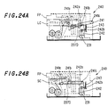
- Timing change lever 241 basically has a similar configuration to timing changer lever 208 in the 2nd embodiment. Specifically, timing change lever 208 is pivotally attached to boss 207D provided in cassette holder 202, and its distal end 241a is fitted through opening 205b of L-cassette guiding piece 205 so as to be projected into the interior of cassette holder 202. Timing change lever 241 is characterized by having 1st and 2nd engaging projections 241b and 241c, in place of 1st and 2nd openings 208d and 208e in timing changer lever 208. First engaging projection 241b is provided near boss 207D, whereas 2nd engaging projection 241c is provided away from boss 207D.
- Shutter 242 is provided along the inner surface of right frame 213A.
- Shutter 242 is provided along frame 213A so as to be movable upward and downward and is urged upward by a spring 243.
- Shutter 242 has a slanting surface 242a at the upper part thereof which is engaged with 1st and 2nd engaging projections 241b and 241c of timing change lever 241.
- Shutter 242 also has an opening 242b which allows completion of the optical path from light emitter 230 to light-receiving sensor 231.
- an L-cassette LC is inserted from an unillustrated inserting port so that it is placed on L-cassette guiding piece 205 of cassette holder 202.
- a further insertion of the L-cassette LC into the chassis interior makes it abut stopper piece 205a, on its inner side edge with respect to the moving direction of L-cassette LC.
- the amount of stroke of cassette holder 202 until opening 242b reaches the sensor optical path between light emitter 230 and light-receiving sensor 231 will be equal to the spacing distance between 1st engaging projection 241b and slanting surface 242a when no L-cassette LC is held. Since 1st engaging projection 241b is more distant from slanting surface 242a than 2nd engaging projection 241c, the amount of stroke of cassette holder 202 when an L-cassette LC is held, is greater than the amount of stroke when an S-cassette SC is held. Therefore, the L-cassette LC held in cassette holder 202 moves deeper toward the chassis interior.
- an S-cassette SC is inserted from an unillustrated inserting port so that it is placed on S-cassette guiding piece 206 of cassette holder 202.
- a further insertion of the S-cassette SC into the chassis interior makes it abut stopper piece 206a, on its inner side edge with respect to the moving direction of SC-cassette SC.
- the amount of stroke of cassette holder 202 until opening 242b reaches the sensor optical path between light emitter 230 and light-receiving sensor 231 will be equal to the spacing distance between 2nd engaging projection 241c and slanting surface 242a when no S-cassette SC is held. Since 2nd engaging projection 241c is closer to slanting surface 242a than 1st engaging projection 241b, the amount of stroke of cassette holder 202 when an S-cassette SC is held is smaller than the amount of stroke when an L-cassette LC is held. Therefore, the S-cassette SC held in cassette holder 202 does not move deeper toward the chassis interior.
- a cassette loading device 245 will be illustrated with reference to Figs.25A and 25B.
- This cassette loading device 245 is a variation of the third embodiment, therefore, identical or like components are allotted with the same reference numerals and the detailed description of those will be omitted.
- cassette loading device 245 is characterized by having a cassette loading switch 246 comprised of a leaf switch.
- Cassette loading switch 246 is provided on the inner side of right frame 213A in such a position that it will become engaged with 1st and 2nd engaging projection 241b and 241c.
- an L-cassette LC is inserted from an unillustrated inserting port so that it is placed on L-cassette guiding piece 205 of cassette holder 202.
- a further insertion of the L-cassette LC into the chassis interior makes it abut stopper piece 205a, on its inner side edge with respect to the moving direction of LC-cassette LC.
- an S-cassette SC is inserted from an unillustrated inserting port so that it is placed on S-cassette guiding piece 206 of cassette holder 202.
- a further insertion of the S-cassette SC into the chassis interior makes it abut stopper piece 206a, on its inner side edge with respect to the moving direction of S-cassette SC.
- cassette loading switch 246 When the rear side face, with respect to the cassette's direction of movement, of the S-cassette SC becomes substantially flush with the VTR front panel FP (at the same position as the front ends of frames 213A and 213B, or in Fig.25B, at a position which is slightly depressed toward the chassis interior from the VTR front panel FP), cassette loading switch 246 will be set into the ON state, so that the cassette in-pulling operation will start from that position.
- a cassette loading device 250 comprises an L-cassette holder 251 and an S-cassette holder 252 as shown in Figs.26-28.
- S-cassette holder 252 is made to fit on L-cassette holder 251 in a slidable manner along the cassette's direction of movement.
- L-cassette holder 251 is integrally formed of a top portion 253, left and right side portions 254, and L-cassette guiding pieces 255 for guiding the undersurface of L-cassette LC.
- L-cassette guiding piece 255 has a stopper piece 255a which has been formed upright to bear the front part of L-cassette LC.
- the L-cassette guiding piece 255 on the right in Fig.26 has an opening 255b into which an aftermentioned timing change lever 262 is fitted.
- Leaf springs 256 for pressing L-cassette are press fitted in top portion 253.
- the distance between left and right L-cassette guiding pieces 255 is set equal to or greater than the width of S-cassette SC.
- L-holder side plates 258 are fixed to bosses 257 with screws.
- a coupling gear 259 and a fixed rack guiding boss 260 are provided on the inner side of L-holder side plate 258.
- Coupling gear 259 is composed of two different-sized gears having different pitch circle diameters, a large-diametric gear part 259a and a small-diametric gear part 259b integrally formed concentrically, and is attached rotatably to L-holder side plate 258.
- Provided on the outer side of L-holder side plate 258 are 1st to 3rd slider axles 261A, 261B and 261C and a boss 261D.
- a guide slot 258a extending horizontally is formed in L-holder side plate 258.
- Boss 261D is provided only on one of L-holder side plates 258, located on the right side in Fig.26, and timing change lever 262 is attached swayably thereto.
- Timing change lever 262 basically has a similar configuration as in the timing change lever 208 shown in Fig.21 though it is attached at a different position.
- timing change lever 262 is pivotally supported at the central portion across its width by boss 261D.
- An end portion, designated at 262a, on the near side, with respect to the cassette's direction of insertion, of timing change lever 262 is bent so as to fit along the bottom surface of L-cassette guiding piece 255.
- a distal end 262b of end portion 262a is bent upward so that it can be fitted through opening 255b of L-cassette guiding piece 255. Since opening 255b is provided in L-cassette guiding piece 255, distal end 262b will engage the bottom of the L-cassette LC only when an L-cassette LC is loaded to cassette holder 251, whereas it will not engage the bottom of the S-cassette SC when an S-cassette SC is loaded.
- Timing change lever 262 On the inner side with respect to the cassette's direction of insertion is formed in an L-shape and is positioned below side portion 254. This end portion 262c has a 1st opening 262d and a 2nd opening 262e. First and second openings 262d and 262e are arranged along the length of end portion 262c. Timing change lever 262 thus configured is urged by a spring 263 in such a direction that its distal end 262b projects from opening 255b (in clockwise direction in Fig.26).
- a fixed rack 264 is provided between side portion 254 and L-holder side plate 258.
- Fixed rack 264 has a first rack gear 264a meshing large-diametric gear part 259a, a guide slot 264b engaged with fixed rack guide boss 260 and a position regulating boss 264c.
- S-cassette holder 252 is composed of a top portion 265, left and right side portions 266 and S-cassette guiding pieces 267 for guiding the undersurface of S-cassette SC.
- S-cassette guiding piece 267 has a stopper piece 267a which has been formed upright to bear the front part of S-cassette SC.
- Leaf springs 268 for pressing S-cassette are press fitted in top portion 265.
- a movable rack 269 Fixed on the outer face of side portion 266 is a movable rack 269, which has a 2nd rack gear 269a and a sliding bosses 269b.
- Second rack gear 269a is meshed with small-diametric gear part 259b of coupling gear 259. Sliding bosses 269b engage with guide slot 258a of L-holder side plate 258.
- top portion 253 of L-cassette holder 251 are clearance holes 253a for leaf springs 268 on S-cassette holder 252.
- Mech-chassis 270 which supports cassette loading device 250, has a pair of right and left frames 271A and 271B standing upright parallel to each other. A top plate 272 is provided between frames 271A and 271B. Pivotally supported between frames 271A and 271B is a cassette port door 273 for opening and closing the port for both cassette holders 251 and 252.
- Frames 271A and 271B each have a 1st L-shaped guide slot 271a engaged with and guiding the 1st slider axle 261A of L-cassette side plate 258, and a 2nd L-shaped guide slot 271b engaged with and guiding 2nd slider axle 261B, whereby L-cassette side plate 258 is supported so as to be able to slide along guide slots 271a and 271b.
- frames 271A and 271B each include: a rib-formed guide slot 271c which is engaged with 3rd slider axle 261C to guide the downward movement when both cassette holders 251 and 252 move downwards; and a guide slot 271d which guides position regulating boss 264c of fixed rack 264 in the vertical direction and inhibits the motion in the cassette's direction of movement.
- Drive arms 274A and 274B are pivoted on the inner sides of respective frames 271A and 271B so that they are free to rock back and forth.
- Drive arms 274A and 274B each have a semicircular gear 274a formed coaxially with the support axle thereof.
- Rotationally supported between left and right frames 271A and 271B is a link shaft 275.
- This link shaft 275 has timing gears 276, 276 attached at both ends in phase.
- Timing gears 276, 276 are in mesh with semicircular gears 274a of drive arms 274A and 274B, respectively, so that both drive arms 274A and 274B will rotate integrally.
- Drive arms 274A and 274B have respective slots 274b, 274b, which extend along the length thereof. This slot 274b is engaged with 1st slider axle 261A which also fits through 1st guide slot 271a.
- Left drive arm 274B has another semicircular gear 274c which is formed coaxially with the support axle of drive arm 274B.
- Drive arms 274A and 274B each have a cassette pressing spring 274d which urges 1st slider axle 261A engaging slot 274b, in such a direction as to press the distal end of drive arm 274A or 274B toward the chassis interior (in the clockwise direction in Fig.27, and in the counterclockwise direction in Fig.28).
- a light-receiving sensor 281 for receiving the sensor light from a light emitter provided for mech-chassis 270 (this light emitter is not shown in the figure but is provided in the same position as light emitter 230 in the 2nd embodiment).
- the outer side of left frame 271B has 4th through 6th slider axles 277A, 277B and 277C press fitted thereon.
- a double-acting plate 278 is provided on the outer side of left frame 271B.
- Double-acting plate 278 has guide slots 278a, 278b and 278c which are engaged with 4th through 6th slider axles 277A to 277C, respectively, so that double-acting plate 278 will be able to move back and forth relative to frame 271B in the cassette's direction of insertion.
- Double-acting plate 278 has a rack gear 278d meshed with semicircular gear 274c of drive arm 274B so that double-acting plate 278 will move linearly in the cassette's direction of insertion as drive arm 274B moves swayingly.
- driving plate 279 Provided on the outer side of double-acting plate 278 is a driving plate 279, which has guide slots 279a, 279b and 279c engaged with 4th through 6th slider axles 277A to 277C, respectively.
- driving plate 279 will be able to move back and fourth relative to frame 271B in the cassette's direction of insertion.
- a double-acting spring 280 a tension spring is provided between double-acting plate 278 and driving plate 279 at their inner ends thereof.
- Driving plate 279 has a rack gear 279e which, similarly to rack gear 278d, is in mesh with semicircular gear 274c, and another rack gear 279f which receives the driving force from an unillustrated driver motor for loading.
- Rack gear 278d is formed with such a length as to be in mesh with semicircular gear 274c from the beginning of the rocking movement of drive arm 274B to the end.
- Rack gear 279e is formed with such a length that it will not be in mesh at the beginning of the rocking movement of drive arm 274B but will become engaged with semicircular gear 274c of drive arm 274B in the course of rocking movement of the arm to the end.
- cassette loading device 250 since fixed rack 264 is inhibited from moving in the cassette's direction of movement by guide slot 271d, when L-cassette holder 251 is moved, S-cassette holder 252 will also move through coupling gear 259 and fixed rack 264. In this case, S-cassette holder 252 undergoes extra movement compared to L-cassette holder 251, corresponding to the ratio of the pitch circle diameters of large-diametric gear part 259a and small-diametric gear part 259b.
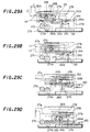
- the horizontal conveyance starts from the inserted positions of L- and S-cassettes LC and SC (at the positions where cassettes LC and SC abut stopper pieces 255a and 267a, respectively). Since the L-cassette holder 251 is located at a more inward position relative to the chassis interior, it is possible to reduce the projected amount (designated at LD in Fig.29A) of L-cassette LC at its inserted position from the VTR front panel FP.
- the projected amount (designated at SD in Fig.29A) of S-cassette SC at its inserted position from the VTR front panel FP can be made coincident with the aforementioned projected amount LD.
- FIG.29A an L-cassette LC is inserted from an unillustrated inserting port so that it is placed on L-cassette guiding piece 255 of cassette holder 251.
- a further insertion of the L-cassette LC into the chassis interior makes it abut stopper piece 255a, on its inner side edge.
- the L-cassette LC is pressed against L-cassette guiding piece 255 from above by leaf springs 256, so that it will be stably held inside L-cassette holder 251.
- Movable rack 269 (S-cassette holder 252), which is placed on in mesh with coupling gear 259, also moves horizontally, as coupling gear 259 travels horizontally.
- movable rack 269 (S-cassette holder 252) meshed with small-diametric gear part 259b turned by the rolling of coupling gear 259, moves further toward the chassis interior as it rolls over small-diametric gear part 259b. Therefore, S-cassette holder 252 travels further, which is the distance in which movable rack 269 moves over the rolling small-diametric gear part 259b, than L-cassette holder 251.
- L-holder side plate 258 is guided with its 1st and 2nd slider axles 261A and 261B engaging 1st and 2nd guide slots 271a and 271b of frames 271A and 271B.
- drive arms 274A and 274B whose slots 274b are engaged with 1st slider axles 261A, swayingly move their distal ends toward the chassis interior (in the clockwise direction in Fig.27, and in the counterclockwise direction in Fig.28). Since drive arms 274A and 274B are coupled by link shaft 275, timing gears 276, 276 and semicircular gears 274a, they will sway in synchronism.
- double-acting plate 278 meshed with semicircular gear 274c moves slightly toward the chassis interior. During this, since driving plate 279 will not move, double-acting plate 278 will move whilst extending double-acting spring 280 provided between double-acting plate 278 and driving plate 279.
- timing change lever 262 When double-acting plate 278 has moved toward the chassis interior and with this movement, timing change lever 262 has moved toward the chassis interior by a spacing distance between light-receiving sensor 281 and 1st opening 262d as shown in Fig.29B, 1st opening 262d located on the front side with respect to the cassette's direction of movement becomes positioned in the sensor optical path for light-receiving sensor 281.
- light-receiving sensor 281 receives the sensor light from the light emitter (not shown) provided in mech-chassis 270.
- an unillustrated driving motor is activated, and the driving force is transmitted to rack 279f. Accordingly, driving plate 279 moves toward the chassis interior.
- double-acting plate 278 together with driving plate 279 begins to move toward the chassis interior.
- the amount of stroke of cassette holder 251 until 1st opening 262d reaches the sensor optical path for light-receiving sensor 281 will be equal to the aforementioned spacing distance between light-receiving sensor 281 and 1st opening 262d. Since 1st opening 262d is more distant from light-receiving sensor 281 than 2nd opening 262e, the amount of stroke of L-holder side plate 258 becomes greater. As a result, the amount of stroke of L-cassette holder 251 becomes greater.
- the L-cassette LC held in cassette holder 251 moves deeper toward the chassis interior.
- the rear side face of the cassette with respect to the cassette's direction of movement becomes substantially flush with the VTR front panel FP (at the same position as the front ends of frames 213A and 213B)
- light-receiving sensor 281 will detect the sensor light. Accordingly, the cassette in-pulling operation will start as described hereinbelow from a position where the L-cassette LC is only marginally projected out from the VTR front panel FP.
- the cassette in-pulling operation will be made as follows: When double-acting plate 278 is moved toward the chassis interior by driving plate 279, drive arm 274B whose semicircular gear 274c is meshed with rack gear 278d of double-acting plate 278, sways in such a direction that the distal end thereof moves toward the chassis interior (in the clockwise direction in Figs.29A-29D) while drive arm 274A also sways in synchronism.
- an unillustrated cassette size detecting switch detects the inserted cassette as to be an L-cassette LC, to thereby drive an unillustrated reel table shifting mechanism.
- the reel tables are adjusted so that the distance between the reel tables will match the reel distance of L-cassette LC.
- the L-cassette LC which already has been pulled in to the lowest position of the in-pulling operation, is placed on four cassette stays (not shown) planted on mech-chassis 270.
- drive arms 274A and 274B urged by cassette pressing springs 274d press 1st slider axles 261A downwards. Therefore, the L-cassette LC becomes pressed in contact with the aforementioned cassette stays with its bottom slightly spaced away from L-cassette guiding piece 255.
- FIG.30A an S-cassette SC is inserted from an unillustrated inserting port so that it is placed on S-cassette guiding piece 267 of cassette holder 252.
- a further insertion of the S-cassette SC into the chassis interior makes the inner side edge thereof abut stopper piece 267a of S-cassette guiding piece 267.
- the S-cassette SC is pressed against S-cassette guiding piece 267 from above by leaf springs 268, so that it will be stably held inside S-cassette holder 252.
- S-cassette holder 252 placed on coupling gear 259 also travels by the distance in which coupling gear 259 moves toward the chassis interior. Therefore, as S-cassette holder 252 is pushed in, L-cassette holder 251 also moves, but S-cassette holder 252 is moved more than L-cassette holder 251.
- L-holder side plate 258 is guided with its 1st and 2nd slider axles 261A and 261B engaging 1st and 2nd guide slots 271a and 271b of frames 271A and 271B.
- drive arms 274A and 274B whose slots 274b are engaged with 1st slider axles 261A, swayingly move their distal ends toward the chassis interior (in the clockwise direction in Figs.30A and 30B). Since drive arms 274A and 274B are coupled by link shaft 275, timing gears 276, 276 and semicircular gears 274a, they will sway in synchronism.
- double-acting plate 278 meshed with semicircular gear 274c moves slightly toward the chassis interior. During this, since driving plate 279 will not move, double-acting plate 278 will move whilst extending double-acting spring 280 provided between double-acting plate 278 and driving plate 279.
- timing change lever 262 (L-holder side plate 258) has moved toward the chassis interior by a spacing distance between light-receiving sensor 281 and 2nd opening 262e as shown in Fig.30B, 2nd opening 262e located on the inner side with respect to the cassette's direction of movement becomes positioned in the sensor optical path for light-receiving sensor 281.
- light-receiving sensor 281 receives the sensor slight from the light emitter (not shown) provided in mech-chassis 270.
- an unillustrated driving motor is activated, and the driving force is transmitted to rack 279f. Accordingly, driving plate 279 moves toward the chassis interior.
- double-acting plate 278 together with driving plate 279 begins to move toward the chassis interior.
- the amount of stroke of S-cassette holder 252 until 2nd opening 262e reaches the sensor optical path for light-receiving sensor 281 will be equal to the aforementioned spacing distance between light-receiving sensor 281 and 2nd opening 262e. Since 2nd opening 262e is closer to light-receiving sensor 281 than 1st opening 262d, the amount of stroke of L-holder side plate 258 becomes smaller. As a result, the amount of stroke of S-cassette holder 252 also becomes smaller.
- 1st to 3rd slider axles 261A to 261C are provided for L-cassette holder 251 so as to drive it by means of drive arms 274A and 274B, these 1st to 3rd slider axles 261A to 261C may be provided in S-cassette holder 252.
- S-cassette holder 252 is arranged in such a manner as to enclose L-cassette holder 251, but it is also possible to make such an arrangement that L-cassette holder 251 encloses S-cassette holder 252.
- the invention thus configurated has the following effects.
- the inputting means moves one cassette holder with a different amount of stroke from the pushed amount of stroke for the magnetic tape cassette inserted in the other cassette holder, it is possible to feed a magnetic tape cassette placed in either cassette holder, in the most suitable fashion relative to the outside dimensions of the cassette, thus preventing occurrence of malfunctions and damage to the appliance due to an improper cassette feeding. Further, it is possible to feed any of the different kinds of magnetic tape cassettes by the same feeding operation, therefore it becomes possible to facilitate the cassette feeding operation, resulting in improved operativeness.
- the inpulling means moves one cassette holder with a different amount of stroke from the pushed amount of stroke for the other cassette holder, it becomes possible to differentiate the starting position where each cassette holder receives a respective magnetic tape cassette, in accordance with the outside dimensions of the magnetic tape cassette. As a result, it becomes possible to equalize the projected amounts of the different magnetic tape cassettes from the cassette loading device at the beginning when each cassette is inserted into the holder. This allows the operator to perform the loading operation of magnetic tape cassettes of different types without caring about the outside dimensions of the cassettes, thus attaining easy and improved operativeness.
- the changing means can change the starting position of the in-pulling operation of each magnetic tape cassette in accordance with its outside dimensions, it is possible to load a magnetic tape cassette in the most suitable fashion relative to the outside dimensions of the cassette, thus preventing occurrence of malfunctions and damage to the appliance due to an improper cassette feeding. Further, it is possible to load any of the different kinds of magnetic tape cassettes by the same feeding operation, therefore it becomes possible to realize easy handling in cassette loading operation as well as to improved operativeness.
Landscapes
- Automatic Tape Cassette Changers (AREA)
Applications Claiming Priority (4)
| Application Number | Priority Date | Filing Date | Title |
|---|---|---|---|
| JP8123279A JPH09306067A (ja) | 1996-05-17 | 1996-05-17 | カセットローディング装置 |
| JP8123280A JPH09306068A (ja) | 1996-05-17 | 1996-05-17 | カセットローディング装置 |
| JP123279/96 | 1996-05-17 | ||
| JP123280/96 | 1996-05-17 |
Publications (1)
| Publication Number | Publication Date |
|---|---|
| EP0807933A1 true EP0807933A1 (fr) | 1997-11-19 |
Family
ID=26460255
Family Applications (1)
| Application Number | Title | Priority Date | Filing Date |
|---|---|---|---|
| EP97303373A Withdrawn EP0807933A1 (fr) | 1996-05-17 | 1997-05-16 | Dispositif de chargement de cassette |
Country Status (2)
| Country | Link |
|---|---|
| US (1) | US5920442A (fr) |
| EP (1) | EP0807933A1 (fr) |
Cited By (2)
| Publication number | Priority date | Publication date | Assignee | Title |
|---|---|---|---|---|
| GB2419728A (en) * | 2004-10-28 | 2006-05-03 | Hewlett Packard Development Co | Cartridge loading apparatus |
| GB2419729A (en) * | 2004-10-28 | 2006-05-03 | Hewlett Packard Development Co | Cartridge loading devices |
Families Citing this family (4)
| Publication number | Priority date | Publication date | Assignee | Title |
|---|---|---|---|---|
| US6735154B2 (en) | 2001-01-31 | 2004-05-11 | Dphi Acquisitions, Inc. | Device and method for detecting cartridge readiness to load in a data storage system |
| US20020131201A1 (en) * | 2001-01-31 | 2002-09-19 | Dataplay, Inc. | Mechanism and method for limiting ejection of data cartridge from a disk drive |
| US6829120B2 (en) * | 2001-01-31 | 2004-12-07 | Dphi Acquisitions, Inc. | Data cartridge load/unload mechanism for disk drive |
| JP4687386B2 (ja) * | 2005-10-25 | 2011-05-25 | ミツミ電機株式会社 | カートリッジホルダ装置 |
Citations (6)
| Publication number | Priority date | Publication date | Assignee | Title |
|---|---|---|---|---|
| EP0316156A2 (fr) * | 1987-11-10 | 1989-05-17 | Victor Company Of Japan, Limited | Système de chargement de cassette à bande |
| EP0356184A2 (fr) * | 1988-08-23 | 1990-02-28 | Victor Company Of Japan, Ltd. | Mécanisme d'extraction de bande pour appareil d'enregistrement/reproduction magnétique pour usage sélectif avec des cassettes à bande de deux dimensions différentes |
| EP0374899A2 (fr) * | 1988-12-20 | 1990-06-27 | Sony Corporation | Système de chargement de cassette à bande magnétique dans un appareil d'enregistrement et/ou de reproduction |
| US5067036A (en) * | 1989-02-28 | 1991-11-19 | Hitachi, Ltd. | Cassette loading mechanism for accommodating cassettes of various sizes |
| EP0557726A2 (fr) * | 1992-02-28 | 1993-09-01 | Sharp Kabushiki Kaisha | Lecteur de cassette à bande compatible avec des cassettes à bande de différent format |
| EP0570134A2 (fr) * | 1992-05-06 | 1993-11-18 | Matsushita Electric Industrial Co., Ltd. | Appareil de chargement de cassette |
Family Cites Families (1)
| Publication number | Priority date | Publication date | Assignee | Title |
|---|---|---|---|---|
| JPH05128675A (ja) * | 1991-11-05 | 1993-05-25 | Sony Corp | カセツト・オートチエンジヤー |
-
1997
- 1997-04-17 US US08/839,319 patent/US5920442A/en not_active Expired - Fee Related
- 1997-05-16 EP EP97303373A patent/EP0807933A1/fr not_active Withdrawn
Patent Citations (6)
| Publication number | Priority date | Publication date | Assignee | Title |
|---|---|---|---|---|
| EP0316156A2 (fr) * | 1987-11-10 | 1989-05-17 | Victor Company Of Japan, Limited | Système de chargement de cassette à bande |
| EP0356184A2 (fr) * | 1988-08-23 | 1990-02-28 | Victor Company Of Japan, Ltd. | Mécanisme d'extraction de bande pour appareil d'enregistrement/reproduction magnétique pour usage sélectif avec des cassettes à bande de deux dimensions différentes |
| EP0374899A2 (fr) * | 1988-12-20 | 1990-06-27 | Sony Corporation | Système de chargement de cassette à bande magnétique dans un appareil d'enregistrement et/ou de reproduction |
| US5067036A (en) * | 1989-02-28 | 1991-11-19 | Hitachi, Ltd. | Cassette loading mechanism for accommodating cassettes of various sizes |
| EP0557726A2 (fr) * | 1992-02-28 | 1993-09-01 | Sharp Kabushiki Kaisha | Lecteur de cassette à bande compatible avec des cassettes à bande de différent format |
| EP0570134A2 (fr) * | 1992-05-06 | 1993-11-18 | Matsushita Electric Industrial Co., Ltd. | Appareil de chargement de cassette |
Cited By (6)
| Publication number | Priority date | Publication date | Assignee | Title |
|---|---|---|---|---|
| GB2419728A (en) * | 2004-10-28 | 2006-05-03 | Hewlett Packard Development Co | Cartridge loading apparatus |
| GB2419729A (en) * | 2004-10-28 | 2006-05-03 | Hewlett Packard Development Co | Cartridge loading devices |
| GB2419728B (en) * | 2004-10-28 | 2007-01-17 | Hewlett Packard Development Co | Cartridge loading apparatus |
| GB2419729B (en) * | 2004-10-28 | 2007-03-28 | Hewlett Packard Development Co | Cartridge loading devices |
| US7420768B2 (en) | 2004-10-28 | 2008-09-02 | Hewlett-Packard Development Company, L.P. | Cartridge loading apparatus |
| US8116028B2 (en) | 2004-10-28 | 2012-02-14 | Hewlett-Packard Development Company, L.P. | Cartridge loading devices |
Also Published As
| Publication number | Publication date |
|---|---|
| US5920442A (en) | 1999-07-06 |
Similar Documents
| Publication | Publication Date | Title |
|---|---|---|
| US4841499A (en) | Multi-disc player | |
| US4509158A (en) | Disc loading device in a video disc player | |
| EP0764947A2 (fr) | Appareil d'enregistrement et de reproduction | |
| CN100562933C (zh) | 碟片装置 | |
| US20010043552A1 (en) | Apparatus for reproducing an optical disc | |
| US4794478A (en) | Improved loading device for cassette recording playback apparatus | |
| KR100251249B1 (ko) | 테이프 카셋트의 기록 및 재생 장치 | |
| US5920442A (en) | Cassette loading device | |
| US6567369B2 (en) | Disc reproducing apparatus | |
| US4115826A (en) | Cartridge type magnetic tape recorders | |
| US6515954B1 (en) | Recording and/or playback apparatus of a recording medium | |
| US5126898A (en) | Automatic cassette changer for tape player | |
| US6424603B1 (en) | Library apparatus of storage media | |
| US5598984A (en) | Reel table moving device for video cassette tape recorder | |
| JP2564625B2 (ja) | 磁気記録再生装置 | |
| US5828647A (en) | Disk changer with reduced driving time | |
| EP1005039B1 (fr) | Appareil de lecture de disques | |
| US20040190390A1 (en) | Disc tray in disc device | |
| JPH03283044A (ja) | カセットローダ装置 | |
| JPH09306068A (ja) | カセットローディング装置 | |
| JPH09306067A (ja) | カセットローディング装置 | |
| JPH08161807A (ja) | ディスクローディング装置 | |
| JPH0325317Y2 (fr) | ||
| KR100307356B1 (ko) | 디스크 드라이버의 디스크 이송장치 | |
| JP2665689B2 (ja) | 車載用ディスクプレーヤ |
Legal Events
| Date | Code | Title | Description |
|---|---|---|---|
| PUAI | Public reference made under article 153(3) epc to a published international application that has entered the european phase |
Free format text: ORIGINAL CODE: 0009012 |
|
| AK | Designated contracting states |
Kind code of ref document: A1 Designated state(s): DE FR GB |
|
| 17P | Request for examination filed |
Effective date: 19980119 |
|
| 17Q | First examination report despatched |
Effective date: 20010702 |
|
| STAA | Information on the status of an ep patent application or granted ep patent |
Free format text: STATUS: THE APPLICATION IS DEEMED TO BE WITHDRAWN |
|
| 18D | Application deemed to be withdrawn |
Effective date: 20011113 |