EP0808665A2 - Valve à piston - Google Patents
Valve à piston Download PDFInfo
- Publication number
- EP0808665A2 EP0808665A2 EP97107993A EP97107993A EP0808665A2 EP 0808665 A2 EP0808665 A2 EP 0808665A2 EP 97107993 A EP97107993 A EP 97107993A EP 97107993 A EP97107993 A EP 97107993A EP 0808665 A2 EP0808665 A2 EP 0808665A2
- Authority
- EP
- European Patent Office
- Prior art keywords
- liquid
- extension
- piston valve
- cylinder
- valve according
- Prior art date
- Legal status (The legal status is an assumption and is not a legal conclusion. Google has not performed a legal analysis and makes no representation as to the accuracy of the status listed.)
- Granted
Links
Images
Classifications
-
- B—PERFORMING OPERATIONS; TRANSPORTING
- B05—SPRAYING OR ATOMISING IN GENERAL; APPLYING FLUENT MATERIALS TO SURFACES, IN GENERAL
- B05B—SPRAYING APPARATUS; ATOMISING APPARATUS; NOZZLES
- B05B12/00—Arrangements for controlling delivery; Arrangements for controlling the spray area
-
- B—PERFORMING OPERATIONS; TRANSPORTING
- B05—SPRAYING OR ATOMISING IN GENERAL; APPLYING FLUENT MATERIALS TO SURFACES, IN GENERAL
- B05B—SPRAYING APPARATUS; ATOMISING APPARATUS; NOZZLES
- B05B5/00—Electrostatic spraying apparatus; Spraying apparatus with means for charging the spray electrically; Apparatus for spraying liquids or other fluent materials by other electric means
- B05B5/16—Arrangements for supplying liquids or other fluent material
- B05B5/1608—Arrangements for supplying liquids or other fluent material the liquid or other fluent material being electrically conductive
- B05B5/1616—Arrangements for supplying liquids or other fluent material the liquid or other fluent material being electrically conductive and the arrangement comprising means for insulating a grounded material source from high voltage applied to the material
- B05B5/1658—Details
- B05B5/1666—Voltage blocking valves, e.g. with axially separable coupling elements
-
- B—PERFORMING OPERATIONS; TRANSPORTING
- B05—SPRAYING OR ATOMISING IN GENERAL; APPLYING FLUENT MATERIALS TO SURFACES, IN GENERAL
- B05B—SPRAYING APPARATUS; ATOMISING APPARATUS; NOZZLES
- B05B12/00—Arrangements for controlling delivery; Arrangements for controlling the spray area
- B05B12/14—Arrangements for controlling delivery; Arrangements for controlling the spray area for supplying a selected one of a plurality of liquids or other fluent materials or several in selected proportions to a spray apparatus, e.g. to a single spray outlet
- B05B12/1481—Arrangements for controlling delivery; Arrangements for controlling the spray area for supplying a selected one of a plurality of liquids or other fluent materials or several in selected proportions to a spray apparatus, e.g. to a single spray outlet comprising pigs, i.e. movable elements sealingly received in supply pipes, for separating different fluids, e.g. liquid coating materials from solvent or air
-
- B—PERFORMING OPERATIONS; TRANSPORTING
- B05—SPRAYING OR ATOMISING IN GENERAL; APPLYING FLUENT MATERIALS TO SURFACES, IN GENERAL
- B05B—SPRAYING APPARATUS; ATOMISING APPARATUS; NOZZLES
- B05B5/00—Electrostatic spraying apparatus; Spraying apparatus with means for charging the spray electrically; Apparatus for spraying liquids or other fluent materials by other electric means
- B05B5/16—Arrangements for supplying liquids or other fluent material
- B05B5/1608—Arrangements for supplying liquids or other fluent material the liquid or other fluent material being electrically conductive
- B05B5/1616—Arrangements for supplying liquids or other fluent material the liquid or other fluent material being electrically conductive and the arrangement comprising means for insulating a grounded material source from high voltage applied to the material
-
- B—PERFORMING OPERATIONS; TRANSPORTING
- B05—SPRAYING OR ATOMISING IN GENERAL; APPLYING FLUENT MATERIALS TO SURFACES, IN GENERAL
- B05B—SPRAYING APPARATUS; ATOMISING APPARATUS; NOZZLES
- B05B5/00—Electrostatic spraying apparatus; Spraying apparatus with means for charging the spray electrically; Apparatus for spraying liquids or other fluent materials by other electric means
- B05B5/16—Arrangements for supplying liquids or other fluent material
- B05B5/1608—Arrangements for supplying liquids or other fluent material the liquid or other fluent material being electrically conductive
- B05B5/1616—Arrangements for supplying liquids or other fluent material the liquid or other fluent material being electrically conductive and the arrangement comprising means for insulating a grounded material source from high voltage applied to the material
- B05B5/1625—Arrangements for supplying liquids or other fluent material the liquid or other fluent material being electrically conductive and the arrangement comprising means for insulating a grounded material source from high voltage applied to the material the insulating means comprising an intermediate container alternately connected to the grounded material source for filling, and then disconnected and electrically insulated therefrom
-
- Y—GENERAL TAGGING OF NEW TECHNOLOGICAL DEVELOPMENTS; GENERAL TAGGING OF CROSS-SECTIONAL TECHNOLOGIES SPANNING OVER SEVERAL SECTIONS OF THE IPC; TECHNICAL SUBJECTS COVERED BY FORMER USPC CROSS-REFERENCE ART COLLECTIONS [XRACs] AND DIGESTS
- Y10—TECHNICAL SUBJECTS COVERED BY FORMER USPC
- Y10T—TECHNICAL SUBJECTS COVERED BY FORMER US CLASSIFICATION
- Y10T137/00—Fluid handling
- Y10T137/8376—Combined
Definitions
- the invention relates to a piston valve for liquids with potential separation between liquids on the input and output sides at different electrical potentials according to the preamble of claim 1.
- valve can be used to control electrically conductive liquids, such as water-based paint, which are sprayed with electrostatic charge. Potential differences of approximately 100 kV direct voltage can occur between the valve inlet and outlet.
- the invention is therefore based on the object of specifying a piston valve for liquids and with electrical isolation, which has a longer service life.
- a field strength reduction is achieved which leads to a significant improvement in the durability of the valve materials.
- an electrical field strength in the valve body of less than 20 kV / mm can be achieved with potential differences of up to 200 kV.
- the desired field strength reduction can be set by suitable electrode design and by additional electrodes.
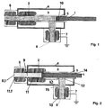
- Figures 1 and 2 show a schematic representation of a preferred valve design.
- a valve piston 1 which is movable therein and which is also made of an electrically insulating material.
- Suitable materials for the electrically insulating cylinder 5 are ceramics and in particular glasses, for example borosilicate glasses.
- the piston is provided with sealing rings 10.
- the piston 1 is displaced in the cylinder 5 with the aid of a pneumatic, hydraulic or electrical drive (not shown), as a result of which a liquid inlet 12 is opened, as shown in FIG. 1, or is closed, as in FIG is shown.
- an additional insulation liquid 14 can also be pressed into the space between valve piston 1 and cylinder 5. This additional insulation liquid 14 should be selected in a media-specific manner since it contaminates the liquid 8 controlled by the valve. If the controlled liquid 8 is water-based paint, paraffin oil offers itself as an additional insulation liquid 14.
- a control electrode 2 is arranged on an extension 11 of the cylinder 5.
- the extension 11 is made of metal.
- this extension can also be made from the electrically insulating material of the cylinder 5 instead of metal.
- the metal should be chemically resistant to the medium, e.g. Be water-based paint.
- a suitable material for the extension 11 is steel.
- the metallic extension 11 can be connected to the electrically insulating cylinder 5, for example by gluing or melting, the connection point being smoothed inside so that the valve piston 1 can slide over the connection point.
- the metallic extension 11 shown is shaped to the control electrode 2, so that there is an electrical connection between the control electrode 2 and the liquid 8.1 located at an outlet 9. If the extension is not made of metal, but of electrically insulating material, e.g. Glass is made, the control electrode 2 is placed and melted so that there is also an electrical connection between the liquid 8.1 and the electrode 2.
- An electrode shape with a radius of curvature of at least three millimeters is particularly suitable. The control electrode 2 is therefore always at the potential of the liquid 8.1 on the outlet side and causes a field strength reduction at the valve.
- Electrical insulation from the outside can be achieved by enveloping the valve arrangement with an electrical insulation means 3, for example polyethylene. If a liquid insulation medium, for example an oil, is used, a correspondingly tight housing 4 around the insulation medium 3 is necessary.
- additional electrodes 6, 7 can be arranged to further reduce the field strength.
- a first additional electrode 6 is arranged on a further extension 11.1. Both for the further extension 11.1 and for the first additional electrode 6, the description of the extension 11 or electrode 2 applies analogously with regard to material, design and potential.
- a second additional electrode 7 is arranged on a feed line 15 and is at ground potential.
Landscapes
- Electrically Driven Valve-Operating Means (AREA)
- Electrostatic Spraying Apparatus (AREA)
- Valve Device For Special Equipments (AREA)
- Compressor (AREA)
- Sliding Valves (AREA)
- Nozzles (AREA)
Applications Claiming Priority (2)
| Application Number | Priority Date | Filing Date | Title |
|---|---|---|---|
| DE19620577 | 1996-05-22 | ||
| DE19620577A DE19620577A1 (de) | 1996-05-22 | 1996-05-22 | Kolbenventil |
Publications (3)
| Publication Number | Publication Date |
|---|---|
| EP0808665A2 true EP0808665A2 (fr) | 1997-11-26 |
| EP0808665A3 EP0808665A3 (fr) | 2001-01-24 |
| EP0808665B1 EP0808665B1 (fr) | 2003-03-05 |
Family
ID=7794992
Family Applications (1)
| Application Number | Title | Priority Date | Filing Date |
|---|---|---|---|
| EP97107993A Expired - Lifetime EP0808665B1 (fr) | 1996-05-22 | 1997-05-16 | Valve à piston |
Country Status (6)
| Country | Link |
|---|---|
| US (1) | US5797590A (fr) |
| EP (1) | EP0808665B1 (fr) |
| JP (1) | JPH10109053A (fr) |
| KR (1) | KR970073738A (fr) |
| AT (1) | ATE233605T1 (fr) |
| DE (2) | DE19620577A1 (fr) |
Cited By (2)
| Publication number | Priority date | Publication date | Assignee | Title |
|---|---|---|---|---|
| WO1999032231A1 (fr) * | 1997-12-18 | 1999-07-01 | LACTEC GmbH Gesellschaft für moderne Lackiertechnik | Procede et dispositif pour isoler un milieu en ecoulement electroconducteur |
| US6849129B2 (en) | 2002-03-13 | 2005-02-01 | Lactec Gmbh | Paint-spraying apparatus for applying liquid coating material to workpieces |
Families Citing this family (4)
| Publication number | Priority date | Publication date | Assignee | Title |
|---|---|---|---|---|
| AU2003225645A1 (en) * | 2002-03-01 | 2003-09-16 | Engineered Machined Products, Inc. | A fluid valve |
| US20050101923A1 (en) * | 2003-11-10 | 2005-05-12 | Leading Edge Innovations, Inc. | Male urinary incontinence sheath |
| US20070102662A1 (en) * | 2005-11-04 | 2007-05-10 | Gliders, Inc. | Valve for single-use and multi-use applications |
| DE102006025549B4 (de) | 2006-06-01 | 2019-04-04 | Eisenmann Se | Ventil |
Family Cites Families (9)
| Publication number | Priority date | Publication date | Assignee | Title |
|---|---|---|---|---|
| US3955796A (en) * | 1975-02-12 | 1976-05-11 | M & J Valve Company | Flow control apparatus |
| DE2838976C2 (de) * | 1978-09-07 | 1983-10-13 | Otto Fritz GmbH Normalschliff-Aufbaugeräte, 6238 Hofheim | Dosierventil |
| DE3431701A1 (de) * | 1984-08-29 | 1986-03-06 | Laborglas Miethke GmbH, 5090 Leverkusen | Glasventil |
| CA2055901A1 (fr) * | 1990-11-26 | 1992-05-27 | James J. Gimple | Revetement automatique utilisant des matieres de revetement conductrices |
| CA2059427C (fr) * | 1991-01-22 | 2000-03-28 | Ichirou Ishibashi | Structure permettant d'empecher les pertes de courant dans les appareils de pulverisation electrostatique |
| US5201493A (en) * | 1992-03-12 | 1993-04-13 | Kim Young M | Electrically insulated ball valve device |
| EP0640017B1 (fr) * | 1992-05-15 | 1998-07-22 | Abb Trallfa Robot A/S | Dispositif de dosage de peinture pour systeme de peinture par pulverisation commande par programme |
| DE4444671A1 (de) * | 1994-12-15 | 1996-06-20 | Abb Patent Gmbh | Lackförderpumpe |
| JP2598767B2 (ja) * | 1994-12-27 | 1997-04-09 | エービービー・インダストリー株式会社 | 塗装用スプレーガン |
-
1996
- 1996-05-22 DE DE19620577A patent/DE19620577A1/de not_active Withdrawn
-
1997
- 1997-05-16 AT AT97107993T patent/ATE233605T1/de not_active IP Right Cessation
- 1997-05-16 EP EP97107993A patent/EP0808665B1/fr not_active Expired - Lifetime
- 1997-05-16 DE DE59709420T patent/DE59709420D1/de not_active Expired - Lifetime
- 1997-05-20 JP JP9129827A patent/JPH10109053A/ja active Pending
- 1997-05-21 KR KR1019970019735A patent/KR970073738A/ko not_active Withdrawn
- 1997-05-22 US US08/861,856 patent/US5797590A/en not_active Expired - Fee Related
Cited By (3)
| Publication number | Priority date | Publication date | Assignee | Title |
|---|---|---|---|---|
| WO1999032231A1 (fr) * | 1997-12-18 | 1999-07-01 | LACTEC GmbH Gesellschaft für moderne Lackiertechnik | Procede et dispositif pour isoler un milieu en ecoulement electroconducteur |
| US6422491B1 (en) | 1997-12-18 | 2002-07-23 | Lactec Gmbh Gesellschaft Fuer Moderne Lackiertechnik | Method and device for isolating an electro-conductive flowing medium |
| US6849129B2 (en) | 2002-03-13 | 2005-02-01 | Lactec Gmbh | Paint-spraying apparatus for applying liquid coating material to workpieces |
Also Published As
| Publication number | Publication date |
|---|---|
| DE19620577A1 (de) | 1997-11-27 |
| ATE233605T1 (de) | 2003-03-15 |
| KR970073738A (ko) | 1997-12-10 |
| US5797590A (en) | 1998-08-25 |
| DE59709420D1 (de) | 2003-04-10 |
| EP0808665A3 (fr) | 2001-01-24 |
| JPH10109053A (ja) | 1998-04-28 |
| EP0808665B1 (fr) | 2003-03-05 |
Similar Documents
| Publication | Publication Date | Title |
|---|---|---|
| DE3712349C2 (de) | Vorrichtung zur Dämpfung von Bewegungsabläufen | |
| DE3043871A1 (de) | Mehrwegeventil | |
| DE3709447A1 (de) | Regelbarer stossdaempfer, insbesondere fuer kraftfahrzeuge | |
| DE3632562A1 (de) | Zweirohr-stossdaempfer | |
| DE3437106A1 (de) | Elektromagnetische stelleinrichtung | |
| EP0066274A1 (fr) | Arrangement de vannes pour augmenter la vitesse de sortie d'un vérin | |
| EP0808665B1 (fr) | Valve à piston | |
| DE3405315C2 (fr) | ||
| WO1993022590A1 (fr) | Soupape pour la regulation du debit d'un fluide s'ecoulant sous pression | |
| DE102004043281A1 (de) | Vorrichtung zum Fixieren von beweglich gelagerten Teilen | |
| EP1332283B1 (fr) | Aiguille d'injection presentant une pointe d'aiguille elastique | |
| DE102014004284B4 (de) | Hochspannungsdurchführung | |
| DE102013110246A1 (de) | Korona-Zündeinrichtung | |
| EP0082933A1 (fr) | Dispositif de détection de la position d'un piston de cylindre | |
| EP0491652B1 (fr) | Dispositif pour déplacer un corps de soupape avec un élément piézoélectrique pour une soupape et application de celui-ci | |
| EP1045732B1 (fr) | Dispositif pour isoler un milieu en ecoulement electroconducteur | |
| DE19735466A1 (de) | Druckmittelmotor für elektrorheologische Flüssigkeiten | |
| DE19955959A1 (de) | Druckmittelmotor auf Basis elektrorheologischer Flüssigkeiten | |
| EP0613515B1 (fr) | Soupape hydraulique haute pression | |
| DE3708656A1 (de) | Elektrostatische spruehpistole | |
| DE3723287C2 (fr) | ||
| DE19746312B4 (de) | Kabelendverschluß oder Kabelmuffe | |
| DE19711193C2 (de) | Vakuumschaltkammer | |
| DE112019002448T5 (de) | Magnetventil | |
| EP0802357A1 (fr) | Vanne électromagnétique |
Legal Events
| Date | Code | Title | Description |
|---|---|---|---|
| PUAI | Public reference made under article 153(3) epc to a published international application that has entered the european phase |
Free format text: ORIGINAL CODE: 0009012 |
|
| AK | Designated contracting states |
Kind code of ref document: A2 Designated state(s): AT BE CH DE DK ES FI FR GB IE IT LI NL PT SE |
|
| PUAL | Search report despatched |
Free format text: ORIGINAL CODE: 0009013 |
|
| AK | Designated contracting states |
Kind code of ref document: A3 Designated state(s): AT BE CH DE DK ES FI FR GB IE IT LI NL PT SE |
|
| 17P | Request for examination filed |
Effective date: 20010602 |
|
| GRAH | Despatch of communication of intention to grant a patent |
Free format text: ORIGINAL CODE: EPIDOS IGRA |
|
| GRAH | Despatch of communication of intention to grant a patent |
Free format text: ORIGINAL CODE: EPIDOS IGRA |
|
| GRAA | (expected) grant |
Free format text: ORIGINAL CODE: 0009210 |
|
| AK | Designated contracting states |
Designated state(s): AT BE CH DE DK ES FI FR GB IE IT LI NL PT SE |
|
| PG25 | Lapsed in a contracting state [announced via postgrant information from national office to epo] |
Ref country code: NL Free format text: LAPSE BECAUSE OF FAILURE TO SUBMIT A TRANSLATION OF THE DESCRIPTION OR TO PAY THE FEE WITHIN THE PRESCRIBED TIME-LIMIT Effective date: 20030305 Ref country code: IT Free format text: LAPSE BECAUSE OF FAILURE TO SUBMIT A TRANSLATION OF THE DESCRIPTION OR TO PAY THE FEE WITHIN THE PRE;WARNING: LAPSES OF ITALIAN PATENTS WITH EFFECTIVE DATE BEFORE 2007 MAY HAVE OCCURRED AT ANY TIME BEFORE 2007. THE CORRECT EFFECTIVE DATE MAY BE DIFFERENT FROM THE ONE RECORDED.SCRIBED TIME-LIMIT Effective date: 20030305 Ref country code: IE Free format text: LAPSE BECAUSE OF FAILURE TO SUBMIT A TRANSLATION OF THE DESCRIPTION OR TO PAY THE FEE WITHIN THE PRESCRIBED TIME-LIMIT Effective date: 20030305 Ref country code: GB Free format text: LAPSE BECAUSE OF FAILURE TO SUBMIT A TRANSLATION OF THE DESCRIPTION OR TO PAY THE FEE WITHIN THE PRESCRIBED TIME-LIMIT Effective date: 20030305 Ref country code: FR Free format text: LAPSE BECAUSE OF NON-PAYMENT OF DUE FEES Effective date: 20030305 Ref country code: FI Free format text: LAPSE BECAUSE OF FAILURE TO SUBMIT A TRANSLATION OF THE DESCRIPTION OR TO PAY THE FEE WITHIN THE PRESCRIBED TIME-LIMIT Effective date: 20030305 |
|
| REG | Reference to a national code |
Ref country code: GB Ref legal event code: FG4D Free format text: NOT ENGLISH |
|
| REG | Reference to a national code |
Ref country code: CH Ref legal event code: EP |
|
| REG | Reference to a national code |
Ref country code: IE Ref legal event code: FG4D Free format text: GERMAN |
|
| REF | Corresponds to: |
Ref document number: 59709420 Country of ref document: DE Date of ref document: 20030410 Kind code of ref document: P |
|
| PG25 | Lapsed in a contracting state [announced via postgrant information from national office to epo] |
Ref country code: AT Free format text: LAPSE BECAUSE OF NON-PAYMENT OF DUE FEES Effective date: 20030516 |
|
| PG25 | Lapsed in a contracting state [announced via postgrant information from national office to epo] |
Ref country code: LI Free format text: LAPSE BECAUSE OF NON-PAYMENT OF DUE FEES Effective date: 20030531 Ref country code: CH Free format text: LAPSE BECAUSE OF NON-PAYMENT OF DUE FEES Effective date: 20030531 Ref country code: BE Free format text: LAPSE BECAUSE OF NON-PAYMENT OF DUE FEES Effective date: 20030531 |
|
| PG25 | Lapsed in a contracting state [announced via postgrant information from national office to epo] |
Ref country code: SE Free format text: LAPSE BECAUSE OF FAILURE TO SUBMIT A TRANSLATION OF THE DESCRIPTION OR TO PAY THE FEE WITHIN THE PRESCRIBED TIME-LIMIT Effective date: 20030605 Ref country code: PT Free format text: LAPSE BECAUSE OF FAILURE TO SUBMIT A TRANSLATION OF THE DESCRIPTION OR TO PAY THE FEE WITHIN THE PRESCRIBED TIME-LIMIT Effective date: 20030605 Ref country code: DK Free format text: LAPSE BECAUSE OF FAILURE TO SUBMIT A TRANSLATION OF THE DESCRIPTION OR TO PAY THE FEE WITHIN THE PRESCRIBED TIME-LIMIT Effective date: 20030605 |
|
| NLV1 | Nl: lapsed or annulled due to failure to fulfill the requirements of art. 29p and 29m of the patents act | ||
| GBV | Gb: ep patent (uk) treated as always having been void in accordance with gb section 77(7)/1977 [no translation filed] |
Effective date: 20030305 |
|
| PG25 | Lapsed in a contracting state [announced via postgrant information from national office to epo] |
Ref country code: ES Free format text: LAPSE BECAUSE OF FAILURE TO SUBMIT A TRANSLATION OF THE DESCRIPTION OR TO PAY THE FEE WITHIN THE PRESCRIBED TIME-LIMIT Effective date: 20030930 |
|
| REG | Reference to a national code |
Ref country code: IE Ref legal event code: FD4D Ref document number: 0808665E Country of ref document: IE |
|
| BERE | Be: lapsed |
Owner name: *ABB RESEARCH LTD Effective date: 20030531 |
|
| PLBE | No opposition filed within time limit |
Free format text: ORIGINAL CODE: 0009261 |
|
| STAA | Information on the status of an ep patent application or granted ep patent |
Free format text: STATUS: NO OPPOSITION FILED WITHIN TIME LIMIT |
|
| REG | Reference to a national code |
Ref country code: CH Ref legal event code: PL |
|
| EN | Fr: translation not filed | ||
| 26N | No opposition filed |
Effective date: 20031208 |
|
| PGFP | Annual fee paid to national office [announced via postgrant information from national office to epo] |
Ref country code: DE Payment date: 20160520 Year of fee payment: 20 |
|
| REG | Reference to a national code |
Ref country code: DE Ref legal event code: R071 Ref document number: 59709420 Country of ref document: DE |