EP0808677A1 - Dispositif pour la fabrication automatique de bagues de compression avec une fermeture à liaison de forme - Google Patents
Dispositif pour la fabrication automatique de bagues de compression avec une fermeture à liaison de forme Download PDFInfo
- Publication number
- EP0808677A1 EP0808677A1 EP97107392A EP97107392A EP0808677A1 EP 0808677 A1 EP0808677 A1 EP 0808677A1 EP 97107392 A EP97107392 A EP 97107392A EP 97107392 A EP97107392 A EP 97107392A EP 0808677 A1 EP0808677 A1 EP 0808677A1
- Authority
- EP
- European Patent Office
- Prior art keywords
- blank
- station
- core
- stamping
- feed
- Prior art date
- Legal status (The legal status is an assumption and is not a legal conclusion. Google has not performed a legal analysis and makes no representation as to the accuracy of the status listed.)
- Granted
Links
- 230000006835 compression Effects 0.000 title claims abstract description 59
- 238000007906 compression Methods 0.000 title claims abstract description 59
- 238000004519 manufacturing process Methods 0.000 title claims abstract description 13
- 239000000463 material Substances 0.000 claims abstract description 47
- 230000009471 action Effects 0.000 claims abstract description 18
- 238000000034 method Methods 0.000 claims abstract description 18
- 230000000875 corresponding effect Effects 0.000 claims description 16
- 230000000295 complement effect Effects 0.000 claims description 9
- 238000006073 displacement reaction Methods 0.000 claims description 7
- 239000011159 matrix material Substances 0.000 claims description 4
- 230000002596 correlated effect Effects 0.000 claims description 2
- 230000004323 axial length Effects 0.000 claims 1
- 238000005452 bending Methods 0.000 description 11
- 238000010276 construction Methods 0.000 description 5
- 238000004080 punching Methods 0.000 description 5
- 230000007246 mechanism Effects 0.000 description 4
- 238000012986 modification Methods 0.000 description 2
- 230000004048 modification Effects 0.000 description 2
- 238000000926 separation method Methods 0.000 description 2
- 238000005520 cutting process Methods 0.000 description 1
- 230000000694 effects Effects 0.000 description 1
- 230000001747 exhibiting effect Effects 0.000 description 1
- 238000010438 heat treatment Methods 0.000 description 1
- 239000010687 lubricating oil Substances 0.000 description 1
- 238000005461 lubrication Methods 0.000 description 1
- 210000002445 nipple Anatomy 0.000 description 1
- 238000003825 pressing Methods 0.000 description 1
- 239000000523 sample Substances 0.000 description 1
- 230000001360 synchronised effect Effects 0.000 description 1
Images




Classifications
-
- B—PERFORMING OPERATIONS; TRANSPORTING
- B21—MECHANICAL METAL-WORKING WITHOUT ESSENTIALLY REMOVING MATERIAL; PUNCHING METAL
- B21D—WORKING OR PROCESSING OF SHEET METAL OR METAL TUBES, RODS OR PROFILES WITHOUT ESSENTIALLY REMOVING MATERIAL; PUNCHING METAL
- B21D53/00—Making other particular articles
- B21D53/16—Making other particular articles rings, e.g. barrel hoops
-
- B—PERFORMING OPERATIONS; TRANSPORTING
- B21—MECHANICAL METAL-WORKING WITHOUT ESSENTIALLY REMOVING MATERIAL; PUNCHING METAL
- B21D—WORKING OR PROCESSING OF SHEET METAL OR METAL TUBES, RODS OR PROFILES WITHOUT ESSENTIALLY REMOVING MATERIAL; PUNCHING METAL
- B21D39/00—Application of procedures in order to connect objects or parts, e.g. coating with sheet metal otherwise than by plating; Tube expanders
- B21D39/03—Application of procedures in order to connect objects or parts, e.g. coating with sheet metal otherwise than by plating; Tube expanders of sheet metal otherwise than by folding
-
- B—PERFORMING OPERATIONS; TRANSPORTING
- B21—MECHANICAL METAL-WORKING WITHOUT ESSENTIALLY REMOVING MATERIAL; PUNCHING METAL
- B21D—WORKING OR PROCESSING OF SHEET METAL OR METAL TUBES, RODS OR PROFILES WITHOUT ESSENTIALLY REMOVING MATERIAL; PUNCHING METAL
- B21D43/00—Feeding, positioning or storing devices combined with, or arranged in, or specially adapted for use in connection with, apparatus for working or processing sheet metal, metal tubes or metal profiles; Associations therewith of cutting devices
- B21D43/02—Advancing work in relation to the stroke of the die or tool
Definitions
- This invention relates to a machine for automatically manufacturing compression rings with a mechanical connection, preferably of the puzzle-lock type.
- Shrinkable compression rings are known in the art which, for the most part, have been made by cutting off rings from tubular stock of various materials. These rings were compressed or shrunk by various means, such as mechanical means, magnetic means, hydraulic means, etc.
- a feed station continuously feeds the flat band from a reel to a stamping station where one end portion of a blank with a mechanical connection, preferably of the puzzle-lock type, is stamped out so that each blank requires two successive cuts which then form cuts of complementary puzzle-lock configuration at opposite ends of the blank.
- the blank is thereupon fed to the deformation station where the flat blank is moved transversely to its feed direction into the bending machine, properly speaking.
- the bending machine has three successive positions in the transverse or axial direction of its core member about which the flat blank is deformed, and includes a number of slide members which are mechanically driven from cams.
- the flat blank In a first position, the flat blank is predeformed into a shape approximating the shape of the finished compression ring with the free end portions of the blank predeformed accurately into a shape necessary to permit closing of the mechanical connection at the free end potions of the blank in the second position.
- the closed compression ring now exhibiting its predetermined diametric dimension, is then subjected in a third position to a swaging operation to improve the locking action and holding ability of the mechanical connection against inadvertent reopening during transport and/or during subsequent use.
- the completed compression ring Upon completion of the various operating steps, the completed compression ring is then ejected.
- the stamping die preferably produces a cut resembling a puzzle lock when severing adjacent band portions.
- the stamping die is so constructed that the mutually facing male and female ends resulting from a stamping operation are again partly reconnected after initial complete separation in order to permit continuation of the feed of two or more successive blanks, each of which requires two cuts spaced in the longitudinal direction as a function of the compression ring size.
- the speed of the continuous feed from the reel to the stamping station and the speed of the intermittent feed from the stamping station to the bending or deforming station are so correlated, preferably with the use of a slack between the reel and the stamping station that the continuous and intermittent feed are properly coordinated to feed the same length of band material within a given cycle of operation.
- the machine preferably includes a straightening device of conventional construction including, for example, pressure rollers arranged staggered and in two rows to remove any curls, kinks or bends from the band resulting from the reeling operation before the band reaches the stamping station.
- a straightening device of conventional construction including, for example, pressure rollers arranged staggered and in two rows to remove any curls, kinks or bends from the band resulting from the reeling operation before the band reaches the stamping station.
- An oiling device of any conventional construction just ahead of the stamping die assures sufficient lubrication of both sides of the band as required by the stamping die before the band reaches the stamping station.
- the method according to a preferred embodiment of this invention includes the steps of feeding from a reel a flat band material to a stamping station where the mechanical connection, preferably of puzzle-lock configuration, is stamped-out, partly reconnecting the previously disconnected mutually facing portions of a mechanical connection, feeding the thus partially reconnected flat blank to the bending or deformation station, again completely separating at the bending station the leading blank from its next-following blank, moving the thus-separated blank into the bending or deforming station in a direction transverse to the feed direction and deforming and completing the compression ring with its mechanical connection in several stages, one disposed behind the other in the transverse direction.
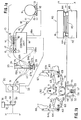
- reference numeral 10 generally designates the feed station for the continuous feed of the band which includes a reel 11 with band material coiled thereon.
- the reel 11 is rotated by a drive mechanism 12 including drive rollers 13 .
- a straightener unit 14 includes upper pressure rollers 15 and lower pressure rollers 15' , preferably arranged staggered to one another, which are intended to remove any curls, kinks or bends in the band that may have occurred during coiling of the band on the reel 11 .
- a feed unit 16 providing a continuous feed of the band 111 and including upper feed rollers 17 and lower feed rollers 17' of conventional construction.
- a control unit 18 of conventional construction electronically controls the operation of the various parts of the machine. The speed of the roller members 13 is thereby controlled by a lever arm 19 having a follower member 19' riding on the band 111 and connected with a potentiometer so as to control the speed of the roller members 13 by way of line 18a .
- a slack control unit generally designated by reference numeral 20 , schematically shown in the drawing, controls the maximum and minimum slack 111'' and 111' in the band, necessitated by the use of a continuous feed in the feed station 10 as contrasted to the intermittent feed of the band required for the stamping operation in the stamping station 40 to enable stamping of the puzzle lock during standstill of the band.
- the slack control unit 20 may be of any conventional construction and may include, for example, two upright members 22a and 22b interconnected at the top and fixedly secured at the bottom at 23 .
- a limit switch 24 is thereby connected to the upper part of the upright member 22b whose switch mechanism is actuated by a downwardly extending probe member 25 adapted to engage with the slack when the slack 111' reaches its predetermined minimum slack to actuate the switch in switch mechanism 24 and feed the information to the control unit 18 by way of line 24a to speed up the continuous feed.
- the maximum predetermined slack also is sensed by a limit switch, for example, by a metallic plate member 26 insulated with respect to ground and mounted in predetermined position, preferably adjustably on upright members 22a and 22b , whereby wires 27a and 27b are mounted over the upright members 22a and 22b .
- the band 111 is normally electrically grounded by any conventional means so that with a slack 111'' exceeding the maximum intended slack, it will apply ground to the plate member 26 , previously insulated with respect to ground, whereby grounding of the plate member 26 is applied to the control unit by way of connector 28 and line 28a causing the continuous feed to slow down.
- the information fed to the control unit 18 by way of lines 24a and 28a is thus used to control the speed of the feed station 10 , 11 , 12 , 13 , 15 and 16 by slowly varying the speed thereof to keep the slack between predetermined limits.
- any other known arrangement may also be used to perform the limit functions of 25 , 24 , 24a and of 26 , 28 , 28a .
- An intermittent feed unit generally designated by reference numeral 30 provides intermittent feed of the band 111 to the stamping unit generally designated by reference numeral 40 by way of an oiling device generally designated by reference numeral 35 which lubricates the upper and lower surface of the band from a reservoir 36 by way of line 37 and branch lines 38 and 39 as required by the stamping die.
- the oiling device 35 is thereby located as close to the stamping unit 40 as possible.
- the stamping unit 40 includes a ram member 41 and a fixed base member 42 which fixedly supports upright, column-like guide members 43 about which the ram member 41 is reciprocably supported by means of the short support members 44 integral with the ram member 41 .
- the stamping die (not shown) is contained within a two-partite housing 45 that contains the stamping die, properly speaking (not shown), to obtain a mechanical connection, preferably of the puzzle-lock type.
- the stamping die consists of four parts, two lower matrix-like members and two upper punching members which are actuated by the ram member 41 in any conventional manner.
- the trailing lower matrix-like member as viewed in the feed direction of the band, is thereby not supported directly on the fixed base member 42 but rather spring-supported by strong springs while the leading lower matrix-like member is supported directly on the fixed base member 42 and the leading upper punching die member is also spring-supported for reasons that will be explained hereinafter in connection with the stamping operation which requires a partial reconnection of successive blanks for the further feed of the stamped-out band material from the stamping station to the deformation station, properly speaking, and generally designated by reference numeral 50 .
- the bending or deformation station 50 has three axial positions in a direction transverse to the feed direction of the band from the stamping station 40 to the deformation station 50 .
- the blank with a mechanical connection preferably of male and female puzzle-lock configurations at the leading and trailing end portions, respectively, is deformed about the core member 51 by means of lower vertically reciprocable slide members 52 and 53 , lateral slide members 60 and 61 adapted to reciprocate in a lateral slightly downwardly inclined direction, and by an upper vertically reciprocable slide member 70 .
- Each slide member 52 , 53 , 60 , 61 and 70 is thereby composed of as many axially arranged sections rigidly interconnected with one another in a given slide member, as required by the number of axial positions in the deformation machine and the deforming surfaces thereof.
- the lower slide member 52 is guided within guide members 54 while the lower slide member 53 is guided within guide members 55 , whereby guide members are provided on both sides of each slide member 52 and 53 , but for convenience sake, only one is shown in some of the figures.
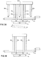
- the slide members 52 and 53 are thereby reciprocated by connecting rods 56 and 57 ( Figure 1b) connected to cam followers which follow appropriate cam surfaces of cam members, all of which are mechanically driven synchronously in the machine.
- slide members 60 and 61 are actuated by pivotal actuating members 64 and 65 whose lower ends are connected to the slide members 60 and 61 by connecting rods 64a and 65a and whose upper ends are provided with cam followers which follow the cam surfaces of mechanically driven cams 66 and 67 .
- Each actuating member 64 and 65 is thereby pivotal about the pivot point 64b and 65b .
- the upper slide member 70 is actuated in its reciprocating movement by an actuating member 72 which is operatively connected by means of a cam follower to a mechanically driven cam (not shown).
- the mechanical connection of the compression rings may be of any known type, e.g., are of the puzzle-lock configuration, as described in my U.S. Patents 5,001,816 and 5,185,908 but is preferably of an improved type of puzzle lock configuration as more fully disclosed also in my copending provisional application entitled "Improved Puzzle-Lock Compression Ring", filed on April 17, 1996, under Serial No. 60/015,700 (D/21569), the subject matter of which is hereby incorporated in its entirety into this application.
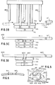
- the male portion generally designated by reference numeral 400 ( Figures 3B, 3C and 3D) of such a mechanical the puzzle-lock-type connection includes a tongue portion 401 ( Figure 5) terminating in an enlarged head portion 402 and is provided with lateral lug portions 403 and 404 .
- the female portion of such a mechanical puzzle-lock-type connection is of complementary shape to the male portion 400 .
- the lateral abutment surfaces 437 and 438 in the area of the enlarged head portion 402 pass over into the transversely extending abutment end surface 439 by way of rounded-off abutment surfaces 440 and 441 which greatly improves the holding ability of the mechanical connection as more fully explained in the aforementioned copending application.
- the areas 410 , 411 and 412 indicated in dash lines are subjected to a swaging action displacing material in the area of the joints of the transversely extending mutually engaging abutment surfaces 432 , 434 and 439 to improve the holding action of the mechanical connection of the compression ring during transportation and/or use thereof to fasten, for example, hoses, axle boots or the like on nipples, axle stubs, etc.
- One cycle of such operation thereby involves the intermittent feeding of band material to the stamping station 40 and out of the stamping station to the deformation station, whereby the stamping-out of the mechanical connection with a preferable puzzle-lock configuration takes place while the intermittent feed is at standstill and includes the severing and partial reconnection of adjoining male and female parts of the mechanical puzzle-lock-type connection, and the cyclical movement of the slide members 50 , 52 , 53 , 60 , 62 and 70 as will be explained hereinafter in further detail.
- each such slide member consists of a number of axially arranged, rigidly interconnected sections corresponding to the number of positions along the axial direction of the core member 51 with a corresponding number of different deforming surfaces.
- parts of the core member and slide members corresponding to the first, second and third positions have been designated in Figures 7, 8, 9, 10, 11 and 12 by corresponding reference numerals of the 100, 200 and 300 series.
- Band material 111 is continuously fed from the feed station 10 by decoiling the same from the reel 11 , actuated by the drive mechanism 12 and the roller members 13 at a continuous speed controlled by the control unit 18 whereby the continuous speed in turn is determined by the position of the lever arm 19 riding with its follower member 19' on the band material 111 and connected to a potentiometer.
- the electronic circuits of the control unit 18 are of conventional type, known to those skilled in the art and forming no part of this invention, a detailed description is dispensed with herein.
- the band material 111 continuously decoiled from the reel 11 is fed to the straightener unit 14 in which any kinks, curls or bends are removed to assure that the band material fed to the continuous feed unit 16 is completely flat.
- Feed rollers 17 and 17' of the feed unit 16 provide a continuous feed of the band material 111 .
- the slack control unit 20 which senses the maximum slack 111'' by means of plate member 26 and the minimum slack 111' by means of follower member 25 , feeds back information to the control unit 18 by way of lines 24a and 28a when the minimum or maximum slack of the band material exceeds predetermined limits.
- This slack control is necessary to correlate the speed of the continuous feed unit 16 to the speed of the intermittent feed unit 30 in order that the length of band material fed per cycle is the same.
- An oiling device generally designated by reference numeral 35 which should be located as close to the stamping unit 40 as possible, includes a reservoir tank 36 for feeding lubricating oil by way of line 37 and branch lines 38 and 39 to the top and bottom of the intermittently fed band material, in an amount as required by the stamping die.
- the stamping unit 40 includes a reciprocating ram member 41 , reciprocating on upright post-like guide members 43 by means of its shorter members 44 , as is conventional in connection with such stamping units.
- the stamping unit 40 further includes a fixed base member 42 on which are supported the upright guide members 43 .
- a two-partite housing 45 fixedly supported on base member 42 contains the stamping die, properly speaking (not shown), to realize the cuts for the mechanical connection, preferably of the puzzle-lock type. Each cut of a stamping operation of such a mechanical connection thereby provides a female puzzle-lock configuration in the trailing piece of band material and a male puzzle-lock configuration in the leading piece of band material.
- the stamping die In order to be able to move blanks cut in the stamping station from the stamping station 40 to the bending or deformation station 50 by means of the intermittently operable feed unit 30 , it is necessary to reconnect again two successive pieces of band material severed by the stamping operation during standstill in a given cycle of operation. For that reason, the stamping die consists of two lower matrix-like parts (not shown) and two upper punching die members (not shown) cooperating with a respective lower matrix member. The lower trailing matrix-like member, as viewed in the feed direction, is thereby spring-supported by a strong spring or springs while the leading upper punching die member of the leading pair is also spring-supported.
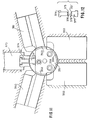
- a spring-loaded plunger or pin member initially presses down in the deformation station on the next-following trailing blank during standstill of the intermittent feed, and complete reseparation is then realized by a plunger or pin member acting on the puzzle-lock male configuration of the next-following blank which is then held down separated by the spring-loaded plunger or pin member until the thus-separated leading blank now designated by reference numeral 111a has been moved transversely to the feed direction by finger-like members 80a , 80b , 80c as shown in Figures 2A and 3A.
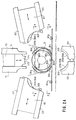
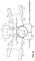
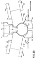
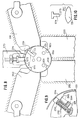
- Figures 1a, 1b, 2A, 2B, 2C and 2D are side elevational views, taken in the axial direction of core member 51
- Figures 3A, 3B, 3C, 3D and 4A are schematic plan views, whereby the position of the various parts always correspond in Figures 2A, 3A and 4A, in Figures 2B and 3B, in Figures 2C and 3C and in Figures 2D and 3D.
- the blank is thereby designated by reference numerals 111a , 111b and 111c in the first, second and third positions of the machine, while the ejected blank is designated by reference numeral 111d .
- the feed path at the point of complete reseparation in the deforming machine includes a slight ramp so that the next-following blank is raised to the level of the preceding blank during the next feed cycle without being obstructed by hitting an abutment.
- Steps 1, 2, 3 and 4 of Figure 14 are schematic side elevational views in Figure 14 while step 5 is a schematic plan view.
- the transverse displacement of the blank illustrated at step 5 in Figure 14 is realized by three reciprocable finger members 80a , 80b and 80c which displace the separated blank into the first position on the core member 51 .
- the blank to form ultimately the compression ring is predeformed so that its end portions conform accurately to the circular configuration needed to permit closing of the puzzle-lock-type mechanical connection.
- the first section 151 of the core member 51 is somewhat oval-shaped with an apple-like configuration.
- the slide members 60 and 61 with their sections 160 and 161 then engage the substantially rectilinearly upwardly extending band portions with their band-engaging deforming surfaces 168 and 169 to deform the band through positions 1' , 2' , 3' , 4' and 5' into position 6' where the section 170 of the upper slide member 70 , upon downward movement, then engages the band with its band-engaging deforming surface 173 to deform the end portions containing the mechanical connection of puzzle lock configurations into position 6'' .
- the thus-predeformed blank Upon retraction of all slide members, the thus-predeformed blank will snap back into position 6''' as a result of the elasticity of the material and assisted by the L-shaped finger members 190a and 190b ( Figure 7) spring-supported by springs 192a and 192b in recesses 191a and 191b in the core section 151 .
- the shorter legs 194a and 194b of the finger-like members 190a and 190b thereby determine the maximum outward projection of these finger-like members. If so desired, the maximum projection of these finger-like members 190a and 190b may also be adjusted as will be described in connection with Figure 9.
- Figure 2A thereby illustrates the position of the slide members in their retracted position during the beginning of a cycle.
- the thus-predeformed blank is then displaced from its first position on the core member 51 by means of reciprocating finger-like members 81a , 81b , 81c and 81d into the second axial position on the core member 51 .
- the blank 111b is deformed into its circular configuration and the mechanical connection of puzzle-lock configuration is closed.
- Figure 8 thereby illustrates the position of the sections 252 , 253 , 260 , 261 and 270 of the slide members 52 , 53 , 60 , 61 and 70 in their extended position.
- the finger member 290 initially projects out of its recess 291 in order that the female puzzle-lock end portion comes to lie above the male puzzle-lock end portion, whereby the finger member 290 is pushed inwardly against the force of the spring 292 as the section 261 of the slide member 62 reaches its inward extended position.
- the upper slide member section 270 with its deformation insert 274 thereby closes the puzzle lock during its downward movement to complete the deformation and closing of the compression ring.
- the thus-deformed and closed compression ring is moved from its second position into the third position of the compression ring 111c by finger members 82a , 82b , 82c and 82d .
- This displacement of the deformed and closed compression ring from position 2 to position 3 at the same time ejects the compression ring 111d previously held in position 3 after being subjected to the swaging action in position 3, to be described more fully hereinafter.
- Figure 13 illustrates a device generally designated by reference numeral 500 for holding the blank in its predetermined position on the core member 51 so that the swaging action always takes place in the proper positions of a mechanical puzzle-lock-type connection.
- the device 500 is thereby arranged in the space between lower slide members 52 and 53 and their guide parts, Figure 13 being a cross-sectional view taken in the axial direction.
- Two pressure members 501 and 502 extending upwardly against the bottom surface of the blank ultimately forming the compression ring are spring-loaded by means of springs 503 and 504 which are accommodated within recesses of housing block 507 and surrounding plunger members 505 and 506 .
- Guide members 508 and 509 thereby guide the pressure members 501 and 502 and parts associated therewith in the upward and downward movement.
- An abutment member 510 is in engagement with the lower ends of the plunger members 505 and 506 to further increase the pressure exerted by the pressure members 501 and 502 on the bottom of the blank forming the compression ring over and above the force normally exerted by springs 503 and 504 .
- the abutment member 510 is thereby connected by connecting member 511 to any device causing upward and downward movement of the abutment member 510 .
- the connecting member 511 is connected with a piston rod of a pneumatic piston unit (not shown) which is so actuated that the connecting member 511 is moved upwardly into the position shown in Figure 13 during the deformation operations in a given cycle to very firmly hold the blank forming the compression ring in its predetermined position, during such deformation operations.
- the abutment member 510 is moved downwardly so as to reduce the pressure exerted by the pressure members 501 and 502 and thereby allow axial displacement of the compression rings though without circumferential movement.
- the springs 503 and 504 are so dimensioned that they hold the compression ring in proper position on the core member 51 yet permit axial movement of the compression rings as required for each operation.
- the deformation surfaces of the slide members engaging with the compression ring blank are as follows.
- Core section 151 has a length of 92 mm. and a height of 70 mm.
- the surfaces 158 and 159 of sections 152 and 153 of the lower slide members 52 and 53 have a radius of curvature of 36.4 mm.
- the surfaces 168 and 169 of sections 160 and 161 of slide members 60 and 61 have a radius of curvature of 36.4 mm.
- the radius of curvature of the curved portion of surface 173 are each 36.4 mm. while the corresponding surfaces on core section 151 have a radius of curvature of 35 mm.
- the diametric dimension of core section 251 of core member 51 is 79.4 mm.
- the curvature 268 and 269 of sections 260 and 261 of slide members 60 and 61 have a radius of curvature of 41.1 mm.
- the insert member 274 in section 270 of the upper slide member 70 has a surface 273 with a radius of curvature also of 41.1 mm.
- the section 351 of core member 51 ( Figure 11) has a diametric dimension again of 79.4 mm. while the surfaces 358 and 359 of sections 352 and 353 of slide members 52 and 53 have again a radius of curvature of 41.1 mm.
- the surfaces 368 and 369 of sections 360 and 361 of slide members 60 and 61 also have a radius of curvature of 41.1 mm.
- the small tooth-like projections 376 on insert member 374 in section 370 of slide member 70 more fully shown in Figure 16, have a height of 0.35 mm. and subtending an angle of 60° as also shown in Figure 16. These tooth-like members 376 are thereby spaced a total of 10.6° in the cicumferential direction.
- the small tooth-like projections 378 on insert member 377 are of similar configuration as the tooth-like projections 376 , i.e., have a height of 0.35 mm. and subtending an angle of 60° spaced 10.6° in the circumferential direction.
- the predeforming of the compression ring in position 1 to facilitate closing of the mechanical connection requires a different handling with compression rings of small diameter because in that case the tapering effects due to the small radius of curvature in the male and female parts of a puzzle-lock-type connection assume greater significance which make it difficult to close the connection due to the smaller openings along the inner circumferential surface of the band portion.
- the machine of this invention is very efficient because by merely interchanging the sections of the various slide members, it is possible to manufacture with the same equipment compression rings of different diametric dimensions. Furthermore, the speed at which the machine can be operated is high, permitting the ready production of fifty-five compression rings per minute.
- All slide members are mechanically actuated by mechanically driven cams while the slide members may be mounted by means of roller bearings to assure frictionless slide movement in their reciprocating movements during a cycle of operation.
- the different sections of the slide members 52 , 53 , 60 , 61 and of the core member 50 are also provided with such surfaces as to permit axial extension of the finger members 81a-81d and 82a-82d , for example, as shown by part-circular recesses and circular openings in the core section 150 of Figure 7 and the appropriately shaped end surfaces in slide member 52 , 53 and 60 , 61 . If the swaging action is not needed or not desired, the machine as described above may also use only two axial positions instead of three.
- the slide members may also be actuated by other means other than mechanical cam operation.
- the coordination of the various movements of the slide members and their timing is best achieved by appropriate design of the cam members and synchronous operation thereof, for example, driven from a single electric motor by way of sprocket-and-chain drives.
Landscapes
- Engineering & Computer Science (AREA)
- Mechanical Engineering (AREA)
- Press Drives And Press Lines (AREA)
- Wire Processing (AREA)
- Package Frames And Binding Bands (AREA)
- Supports For Pipes And Cables (AREA)
- Bending Of Plates, Rods, And Pipes (AREA)
- Manufacture Of Motors, Generators (AREA)
- Manufacturing Of Electrical Connectors (AREA)
Applications Claiming Priority (2)
| Application Number | Priority Date | Filing Date | Title |
|---|---|---|---|
| US1802596P | 1996-05-21 | 1996-05-21 | |
| US18025 | 1996-05-21 |
Publications (2)
| Publication Number | Publication Date |
|---|---|
| EP0808677A1 true EP0808677A1 (fr) | 1997-11-26 |
| EP0808677B1 EP0808677B1 (fr) | 2003-08-06 |
Family
ID=21785837
Family Applications (1)
| Application Number | Title | Priority Date | Filing Date |
|---|---|---|---|
| EP97107392A Expired - Lifetime EP0808677B1 (fr) | 1996-05-21 | 1997-05-05 | Dispositif pour la fabrication automatique de bagues de compression avec une fermeture à liaison de forme |
Country Status (10)
| Country | Link |
|---|---|
| EP (1) | EP0808677B1 (fr) |
| JP (1) | JP4068180B2 (fr) |
| KR (1) | KR100501111B1 (fr) |
| CN (1) | CN1240501C (fr) |
| AR (1) | AR007168A1 (fr) |
| BR (1) | BR9703221A (fr) |
| CA (1) | CA2204063C (fr) |
| DE (1) | DE69723915T2 (fr) |
| ES (1) | ES2203733T3 (fr) |
| ZA (1) | ZA973958B (fr) |
Cited By (4)
| Publication number | Priority date | Publication date | Assignee | Title |
|---|---|---|---|---|
| CN104858325A (zh) * | 2015-06-06 | 2015-08-26 | 欧阳庆丰 | 一种弹性挂钩的扳机夹持输送装置 |
| CN110227743A (zh) * | 2019-07-16 | 2019-09-13 | 西南石油大学 | 一种中梁液压矫正机顶头结构 |
| CN112692186A (zh) * | 2020-12-14 | 2021-04-23 | 广东新宝精密制造股份有限公司 | 一种冲压卷圆装置 |
| EP4414181A1 (fr) * | 2023-02-09 | 2024-08-14 | Meco SA | Outil de frappe formant une étampe, et procédé d'étampage associé |
Families Citing this family (9)
| Publication number | Priority date | Publication date | Assignee | Title |
|---|---|---|---|---|
| CN103128207B (zh) * | 2013-03-11 | 2015-09-02 | 吴成涛 | 弹性挡圈的加工工艺及加工成形装置 |
| CN105382115B (zh) * | 2015-10-14 | 2017-04-12 | 中国矿业大学 | 一种油漆刷铁壳复合机 |
| CN106239157B (zh) * | 2016-08-18 | 2018-04-24 | 安徽省宁国市东波紧固件有限公司 | 一种挡圈加工成型设备 |
| CN107175283B (zh) * | 2017-06-21 | 2019-03-01 | 杭州吉达汽车配件有限公司 | 一种大型双精冲机联动生产线及其工作方法 |
| CN108273882B (zh) * | 2017-11-28 | 2019-07-05 | 苏州和瑞科自动化科技有限公司 | 一种卷圆机构 |
| FR3091203A3 (fr) * | 2018-12-27 | 2020-07-03 | Michelin & Cie | Installation de fabrication de tringles pour pneumatiques comprenant un poste de sertissage pourvu d’un sous-ensemble de preparation automatique de manchons de sertissage |
| CN113714417B (zh) * | 2020-05-25 | 2023-05-23 | 成都秦川物联网科技股份有限公司 | 用于物联网智能燃气表整体封圈制备的成型装置 |
| CN113714340B (zh) * | 2020-05-25 | 2023-07-04 | 成都秦川物联网科技股份有限公司 | 一种物联网智能燃气表整体封圈制备用料带轨道 |
| CN116213585B (zh) * | 2023-05-05 | 2023-07-04 | 江苏巨弘捆带制造有限公司 | 一种钢带冷轧打包扣自动成型设备 |
Citations (4)
| Publication number | Priority date | Publication date | Assignee | Title |
|---|---|---|---|---|
| US1924230A (en) * | 1932-01-14 | 1933-08-29 | Moraine Products Company | Method of making bushings from strip metal |
| GB551367A (en) * | 1942-02-13 | 1943-02-18 | Cleveland Graphite Bronze Co | Method of making bushings |
| US3675460A (en) * | 1970-06-08 | 1972-07-11 | Torin Corp | Four-slide machine with improved mandrel for producing bearings and the like |
| US4543297A (en) * | 1981-11-04 | 1985-09-24 | Saurenman Phillip E | Stiff metal ring and process for making it |
Family Cites Families (1)
| Publication number | Priority date | Publication date | Assignee | Title |
|---|---|---|---|---|
| US230A (en) * | 1837-06-14 | Thomas blanchard |
-
1997
- 1997-04-30 CA CA002204063A patent/CA2204063C/fr not_active Expired - Fee Related
- 1997-05-05 EP EP97107392A patent/EP0808677B1/fr not_active Expired - Lifetime
- 1997-05-05 DE DE69723915T patent/DE69723915T2/de not_active Expired - Lifetime
- 1997-05-05 ES ES97107392T patent/ES2203733T3/es not_active Expired - Lifetime
- 1997-05-08 ZA ZA9703958A patent/ZA973958B/xx unknown
- 1997-05-16 AR ARP970102064A patent/AR007168A1/es unknown
- 1997-05-20 JP JP13000897A patent/JP4068180B2/ja not_active Expired - Fee Related
- 1997-05-20 CN CNB971131228A patent/CN1240501C/zh not_active Expired - Fee Related
- 1997-05-21 KR KR1019970019662A patent/KR100501111B1/ko not_active Expired - Fee Related
- 1997-05-21 BR BR9703221A patent/BR9703221A/pt not_active IP Right Cessation
Patent Citations (4)
| Publication number | Priority date | Publication date | Assignee | Title |
|---|---|---|---|---|
| US1924230A (en) * | 1932-01-14 | 1933-08-29 | Moraine Products Company | Method of making bushings from strip metal |
| GB551367A (en) * | 1942-02-13 | 1943-02-18 | Cleveland Graphite Bronze Co | Method of making bushings |
| US3675460A (en) * | 1970-06-08 | 1972-07-11 | Torin Corp | Four-slide machine with improved mandrel for producing bearings and the like |
| US4543297A (en) * | 1981-11-04 | 1985-09-24 | Saurenman Phillip E | Stiff metal ring and process for making it |
Cited By (6)
| Publication number | Priority date | Publication date | Assignee | Title |
|---|---|---|---|---|
| CN104858325A (zh) * | 2015-06-06 | 2015-08-26 | 欧阳庆丰 | 一种弹性挂钩的扳机夹持输送装置 |
| CN104858325B (zh) * | 2015-06-06 | 2016-10-26 | 欧阳庆丰 | 一种弹性挂钩的扳机夹持输送装置 |
| CN110227743A (zh) * | 2019-07-16 | 2019-09-13 | 西南石油大学 | 一种中梁液压矫正机顶头结构 |
| CN112692186A (zh) * | 2020-12-14 | 2021-04-23 | 广东新宝精密制造股份有限公司 | 一种冲压卷圆装置 |
| EP4414181A1 (fr) * | 2023-02-09 | 2024-08-14 | Meco SA | Outil de frappe formant une étampe, et procédé d'étampage associé |
| US12576666B2 (en) | 2023-02-09 | 2026-03-17 | Meco Sa | Swaging tool forming a stamp, and associated stamping process |
Also Published As
| Publication number | Publication date |
|---|---|
| ES2203733T3 (es) | 2004-04-16 |
| CN1240501C (zh) | 2006-02-08 |
| AU715588B2 (en) | 2000-02-03 |
| KR100501111B1 (ko) | 2005-10-21 |
| JP4068180B2 (ja) | 2008-03-26 |
| CN1169894A (zh) | 1998-01-14 |
| AU2352897A (en) | 1997-11-27 |
| JPH1047545A (ja) | 1998-02-20 |
| EP0808677B1 (fr) | 2003-08-06 |
| MX9703641A (es) | 1998-06-30 |
| DE69723915D1 (de) | 2003-09-11 |
| CA2204063C (fr) | 2005-12-20 |
| DE69723915T2 (de) | 2004-04-22 |
| KR970073787A (ko) | 1997-12-10 |
| ZA973958B (en) | 1997-12-02 |
| BR9703221A (pt) | 1998-09-01 |
| CA2204063A1 (fr) | 1997-11-21 |
| AR007168A1 (es) | 1999-10-13 |
Similar Documents
| Publication | Publication Date | Title |
|---|---|---|
| EP0808677B1 (fr) | Dispositif pour la fabrication automatique de bagues de compression avec une fermeture à liaison de forme | |
| EP0698354B1 (fr) | Eléments d'accouplement pour fermetures à glissière ainsi que leur procédé et dispositif de fabrication | |
| US4363167A (en) | Method of terminating leading ends of a plurality of wires | |
| EP0162119B1 (fr) | Dispositif pour la fabrication d'un emballage à partir d'un flan plat | |
| US3636611A (en) | Apparatus for splicing wires | |
| US10109972B2 (en) | Terminal crimping device | |
| US2333997A (en) | Cathode forming machine | |
| US5909907A (en) | Machine for automatically manufacturing puzzle-lock compression rings | |
| US2370380A (en) | Machine and method for making slide fasteners | |
| US2889866A (en) | Apparatus for forming tubular sleeves | |
| US3245246A (en) | Method and apparatus for assembling terminals and wires | |
| US3646797A (en) | Machine for forming piston ring spacer-expanders from strip stock | |
| EP0023423B1 (fr) | Procédé et dispositif pour déformer la tôle | |
| JP3962156B2 (ja) | クリップ成形方法及びクリップ成形装置 | |
| DE3324252C2 (fr) | ||
| US2804622A (en) | Clip-forming and clinching mechanisms | |
| US3766765A (en) | Machine for forming piston ring spacer-expanders from strip stock | |
| US3762206A (en) | Apparatus for and method of manufacturing cores for ignition coils | |
| CN208682496U (zh) | 一种金属条带印花装置 | |
| US4162572A (en) | Providing solder on electrical contacts | |
| DE3336833C2 (fr) | ||
| US2290263A (en) | Slide fastener element and method of making slide fasteners | |
| US2852842A (en) | Method of forming and applying clasps to envelopes | |
| CN108903227B (zh) | 一种金属壳自动生产设备 | |
| CN208676528U (zh) | 一种金属壳自动生产设备 |
Legal Events
| Date | Code | Title | Description |
|---|---|---|---|
| PUAI | Public reference made under article 153(3) epc to a published international application that has entered the european phase |
Free format text: ORIGINAL CODE: 0009012 |
|
| AK | Designated contracting states |
Kind code of ref document: A1 Designated state(s): BE CH DE ES FR GB IT LI NL SE |
|
| 17P | Request for examination filed |
Effective date: 19980526 |
|
| 17Q | First examination report despatched |
Effective date: 20010906 |
|
| GRAH | Despatch of communication of intention to grant a patent |
Free format text: ORIGINAL CODE: EPIDOS IGRA |
|
| GRAH | Despatch of communication of intention to grant a patent |
Free format text: ORIGINAL CODE: EPIDOS IGRA |
|
| GRAA | (expected) grant |
Free format text: ORIGINAL CODE: 0009210 |
|
| AK | Designated contracting states |
Designated state(s): BE CH DE ES FR GB IT LI NL SE |
|
| REG | Reference to a national code |
Ref country code: GB Ref legal event code: FG4D |
|
| REG | Reference to a national code |
Ref country code: SE Ref legal event code: TRGR |
|
| REG | Reference to a national code |
Ref country code: CH Ref legal event code: EP |
|
| REG | Reference to a national code |
Ref country code: CH Ref legal event code: NV Representative=s name: SULZER MANAGEMENT AG |
|
| REF | Corresponds to: |
Ref document number: 69723915 Country of ref document: DE Date of ref document: 20030911 Kind code of ref document: P |
|
| REG | Reference to a national code |
Ref country code: ES Ref legal event code: FG2A Ref document number: 2203733 Country of ref document: ES Kind code of ref document: T3 |
|
| ET | Fr: translation filed | ||
| PLBE | No opposition filed within time limit |
Free format text: ORIGINAL CODE: 0009261 |
|
| STAA | Information on the status of an ep patent application or granted ep patent |
Free format text: STATUS: NO OPPOSITION FILED WITHIN TIME LIMIT |
|
| 26N | No opposition filed |
Effective date: 20040507 |
|
| PGFP | Annual fee paid to national office [announced via postgrant information from national office to epo] |
Ref country code: GB Payment date: 20100330 Year of fee payment: 14 |
|
| PGFP | Annual fee paid to national office [announced via postgrant information from national office to epo] |
Ref country code: FR Payment date: 20100525 Year of fee payment: 14 Ref country code: ES Payment date: 20100611 Year of fee payment: 14 |
|
| PGFP | Annual fee paid to national office [announced via postgrant information from national office to epo] |
Ref country code: NL Payment date: 20100501 Year of fee payment: 14 Ref country code: IT Payment date: 20100515 Year of fee payment: 14 |
|
| PGFP | Annual fee paid to national office [announced via postgrant information from national office to epo] |
Ref country code: CH Payment date: 20100512 Year of fee payment: 14 Ref country code: BE Payment date: 20100518 Year of fee payment: 14 |
|
| PGFP | Annual fee paid to national office [announced via postgrant information from national office to epo] |
Ref country code: SE Payment date: 20100512 Year of fee payment: 14 Ref country code: DE Payment date: 20100727 Year of fee payment: 14 |
|
| BERE | Be: lapsed |
Owner name: HANS *OETIKER A.G. MASCHINEN- UND APPARATEFABRIK Effective date: 20110531 |
|
| REG | Reference to a national code |
Ref country code: DE Ref legal event code: R119 Ref document number: 69723915 Country of ref document: DE |
|
| REG | Reference to a national code |
Ref country code: DE Ref legal event code: R119 Ref document number: 69723915 Country of ref document: DE |
|
| REG | Reference to a national code |
Ref country code: NL Ref legal event code: V1 Effective date: 20111201 |
|
| REG | Reference to a national code |
Ref country code: CH Ref legal event code: PL |
|
| REG | Reference to a national code |
Ref country code: SE Ref legal event code: EUG |
|
| GBPC | Gb: european patent ceased through non-payment of renewal fee |
Effective date: 20110505 |
|
| PG25 | Lapsed in a contracting state [announced via postgrant information from national office to epo] |
Ref country code: LI Free format text: LAPSE BECAUSE OF NON-PAYMENT OF DUE FEES Effective date: 20110531 Ref country code: CH Free format text: LAPSE BECAUSE OF NON-PAYMENT OF DUE FEES Effective date: 20110531 Ref country code: NL Free format text: LAPSE BECAUSE OF NON-PAYMENT OF DUE FEES Effective date: 20111201 |
|
| REG | Reference to a national code |
Ref country code: FR Ref legal event code: ST Effective date: 20120131 |
|
| PG25 | Lapsed in a contracting state [announced via postgrant information from national office to epo] |
Ref country code: IT Free format text: LAPSE BECAUSE OF NON-PAYMENT OF DUE FEES Effective date: 20110505 |
|
| PG25 | Lapsed in a contracting state [announced via postgrant information from national office to epo] |
Ref country code: BE Free format text: LAPSE BECAUSE OF NON-PAYMENT OF DUE FEES Effective date: 20110531 |
|
| PG25 | Lapsed in a contracting state [announced via postgrant information from national office to epo] |
Ref country code: FR Free format text: LAPSE BECAUSE OF NON-PAYMENT OF DUE FEES Effective date: 20110531 |
|
| PG25 | Lapsed in a contracting state [announced via postgrant information from national office to epo] |
Ref country code: GB Free format text: LAPSE BECAUSE OF NON-PAYMENT OF DUE FEES Effective date: 20110505 |
|
| PG25 | Lapsed in a contracting state [announced via postgrant information from national office to epo] |
Ref country code: SE Free format text: LAPSE BECAUSE OF NON-PAYMENT OF DUE FEES Effective date: 20110506 |
|
| REG | Reference to a national code |
Ref country code: ES Ref legal event code: FD2A Effective date: 20130605 |
|
| PG25 | Lapsed in a contracting state [announced via postgrant information from national office to epo] |
Ref country code: DE Free format text: LAPSE BECAUSE OF NON-PAYMENT OF DUE FEES Effective date: 20111130 |
|
| PG25 | Lapsed in a contracting state [announced via postgrant information from national office to epo] |
Ref country code: ES Free format text: LAPSE BECAUSE OF NON-PAYMENT OF DUE FEES Effective date: 20110506 |