EP0808717B1 - Verriegelungssteckeranordnung - Google Patents
Verriegelungssteckeranordnung Download PDFInfo
- Publication number
- EP0808717B1 EP0808717B1 EP19970303108 EP97303108A EP0808717B1 EP 0808717 B1 EP0808717 B1 EP 0808717B1 EP 19970303108 EP19970303108 EP 19970303108 EP 97303108 A EP97303108 A EP 97303108A EP 0808717 B1 EP0808717 B1 EP 0808717B1
- Authority
- EP
- European Patent Office
- Prior art keywords
- ink
- outlet
- inlet
- valve
- inlet valve
- Prior art date
- Legal status (The legal status is an assumption and is not a legal conclusion. Google has not performed a legal analysis and makes no representation as to the accuracy of the status listed.)
- Expired - Lifetime
Links
- 230000000712 assembly Effects 0.000 claims description 8
- 238000000429 assembly Methods 0.000 claims description 8
- 238000003032 molecular docking Methods 0.000 description 16
- 239000012530 fluid Substances 0.000 description 12
- 239000004698 Polyethylene Substances 0.000 description 5
- -1 polyethylene Polymers 0.000 description 5
- 229920000573 polyethylene Polymers 0.000 description 5
- 238000007373 indentation Methods 0.000 description 4
- 239000000463 material Substances 0.000 description 4
- 230000008878 coupling Effects 0.000 description 2
- 238000010168 coupling process Methods 0.000 description 2
- 238000005859 coupling reaction Methods 0.000 description 2
- 238000003780 insertion Methods 0.000 description 2
- 230000037431 insertion Effects 0.000 description 2
- 230000002411 adverse Effects 0.000 description 1
- 239000012080 ambient air Substances 0.000 description 1
- 239000003086 colorant Substances 0.000 description 1
- 238000001816 cooling Methods 0.000 description 1
- 238000001035 drying Methods 0.000 description 1
- 238000002347 injection Methods 0.000 description 1
- 239000007924 injection Substances 0.000 description 1
- 230000013011 mating Effects 0.000 description 1
- 238000012986 modification Methods 0.000 description 1
- 230000004048 modification Effects 0.000 description 1
- 230000001960 triggered effect Effects 0.000 description 1
- 239000011800 void material Substances 0.000 description 1
- 238000003466 welding Methods 0.000 description 1
Images


Classifications
-
- B—PERFORMING OPERATIONS; TRANSPORTING
- B41—PRINTING; LINING MACHINES; TYPEWRITERS; STAMPS
- B41J—TYPEWRITERS; SELECTIVE PRINTING MECHANISMS, i.e. MECHANISMS PRINTING OTHERWISE THAN FROM A FORME; CORRECTION OF TYPOGRAPHICAL ERRORS
- B41J2/00—Typewriters or selective printing mechanisms characterised by the printing or marking process for which they are designed
- B41J2/005—Typewriters or selective printing mechanisms characterised by the printing or marking process for which they are designed characterised by bringing liquid or particles selectively into contact with a printing material
- B41J2/01—Ink jet
- B41J2/17—Ink jet characterised by ink handling
- B41J2/175—Ink supply systems ; Circuit parts therefor
- B41J2/17503—Ink cartridges
- B41J2/1752—Mounting within the printer
- B41J2/17523—Ink connection
Definitions
- This invention relates to an interlocking connector that can be used to connect an ink supply container to an ink-jet printer.
- Ink-jet printers typically have pens that traverse a sheet of paper or other material.
- the pen has a print head that selectively ejects tiny droplets of ink to form desired characters or images.
- a supply of ink is contained in a reservoir at the pen. This type of ink supply allows for the simple delivery of ink from the reservoir to the print head. The size and weight of the reservoir, however, may adversely affect printer speed because the entire ink supply is moved with the print head.
- the ink supply is contained and located elsewhere on the printer, allowing the pen to traverse the paper at a greater speed.
- a flexible ink delivery tube connects the pen and a supply container.
- the supply container is occasionally replaced.
- ink-jet printers are generally provided with docking stations.
- the docking station houses the supply container.
- the supply container can be easily plugged into and uncoupled from the docking station.
- the docking station includes a fluid interconnect to connect the supply container to the delivery tube.
- a well-sealed fluid interconnect between the docking station and the supply container is necessary. Otherwise, ink may leak from the supply container and damage the printer.
- the fluid interconnect should prevent ink from escaping when the supply container is uncoupled from the docking station so no ink comes in contact with the user.
- EP-A-0 704 309 describes an arrangement for coupling an ink reservoir to a print cartridge, wherein the reservoir and the cartridge are provided with respective valves which enter into a mating relationship and together open their respective valve seats to permit transfer of ink to the cartridge.
- an interlocking connector assembly as defined by claim 7.
- the components of an ink supply system be as easy to recycle as possible.
- a preferred embodiment of the invention provides an interlocking connector assembly for a well-sealed fluid interconnect between an ink supply container and an ink delivery tube.
- the connector assembly includes an outlet valve carried on the ink supply container and an inlet valve carried on the docking station.
- the outlet and inlet valves resist being opened while they are uncoupled.
- the outlet and inlet valves are simultaneously movable into an open position once coupled.
- the outlet and inlet valves cannot be uncoupled until the outlet and inlet valves are simultaneously closed, so that ink cannot escape from the ink supply container or the station.
- the connector assembly ink supply container has few parts, and the parts are made from similar materials, thus making the ink supply easy to recycle.
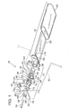
- Fig. 1 is an exploded view of a connector assembly of the present invention.
- Fig. 2 is a perspective view of the connector assembly of Fig. 1 in an open, coupled position.
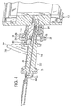
- Fig. 3 is a section view of the connector assembly of Fig. 1 in a closed, uncoupled position.
- Fig. 4 is a section view of the connector assembly of Fig. 1 in an open, coupled position.
- FIG. 1 An interlocking connector assembly 10 in accordance with the present invention is illustrated in Fig. 1.
- the connector assembly 10 connects an ink supply container 16 to a docking station 33 on an ink-jet printer (not shown).
- the illustrated connector assembly 10 has an outlet assembly 12 on the ink container 16 and an inlet assembly 14 connected to the docking station 33.
- the supply container 16 has a container base 54, a flexible ink bag 52, and a hard shell 50.
- the container base 54 is rectangular with rounded corners and has a thickened mid-section 112, as seen in Fig. 3.
- the thickened mid-section 112 has a frustum-shaped indentation 62.
- a bore 42 extends between the wall of the frustum-shaped indentation 62 and the inner edge 120 of the thickened mid-section 112 to open into the bag 52 that is attached at one end to the mid-section 112.
- the container base 54 is made from polyethylene.
- the edge 114 of the container base 54 has an inwardly protruding skirt 110 over which snap-fits the open end 118 of the shell 50.
- the hard shell 50 is made from a low-cost material such as polyethylene and has an inwardly facing annular groove 116.
- the shell 50 is snapped onto the container base 54 such that a ridge on the skirt 110 fits snugly into the groove 116 on the shell 50.
- the shell 50 protects the ink bag 52.
- the ink bag 52 is attached to the thickened mid-section 112 of the container base 54 by, for example, heat-staking. Fluid can flow from the interior of the ink bag 52 through the bore 42 in the mid-section 112. The ink bag 52 is otherwise enclosed.
- the outlet assembly 12 includes a valve holder 36, an outlet valve 20, and a keeper member 18.
- the valve holder 36 is a projecting tube that is either integrally formed with or attached to the container base 54 by, for example, heat-staking or ultrasonic welding.
- the valve holder 36 is preferably made from polyethylene.
- the outlet valve 20 is cylindrical with a frustum-shaped protrusion 56 at the center of the inward end 64.
- the outlet valve 20 has an "L" shaped passageway 44 extending from the outward end 66 of the outlet valve 20, along the axis of the outlet valve 20, and radially to the side of the frustum-shaped protrusion 56.
- the outward end of the passageway 44 is countersunk, and the passageway 44 tapers slightly before extending radially.
- the outlet valve 20 is injection molded from polyethylene and formed with a void 126 therein to facilitate even cooling of the polyethylene and to reduce material.
- the outlet valve 20 fits tightly within the valve holder 36 and is recessed therein so as to resist rotation by hand.
- the frustum-shaped protrusion 56 of the outlet valve 20 fits tightly within the frustum-shaped indentation 62 in the container base 54.
- the outlet valve 20 When the outlet assembly 12 is not coupled to the inlet assembly 14, the outlet valve 20 is in a closed position, in which the passageway 44 is not aligned with or intersecting the bore 42.
- the walls of the frustum-shaped protrusion 56 block fluid flow from the bore 42 of the supply container 16, as shown in Fig. 3.
- the outlet valve 20 is rotatable into an open position, in which the passageway 44 is aligned with the bore 42 to allow fluid flow from the supply container 16, as shown in Fig. 4 and as will be described in greater detail below.
- the outlet valve 20 also has keyways 28, of which there are three in the preferred embodiment (Fig. 1). Each keyway 28 is a "V"-shaped notch that extends axially along the edge of the outlet valve 20. The keyways 28 are equally spaced around the perimeter of the outlet valve 20.
- the outlet valve 20 is held in the valve holder 36 by the stationary keeper member 18.
- the keeper member 18 is ring-shaped and its inner diameter fits snugly around the outer diameter of the valve holder 36.
- the keeper member 18 has legs 68, as best seen in Fig. 1, extending from the outward edge 72 of the keeper member 18 inwardly to the interior of the ring.
- the legs 68 have feet 70 extending radially inward and perpendicular to the legs 68. The undersides of the feet 70 abut the outward end 66 of the outlet valve 20, thereby to hold the outlet valve 20 tightly against the frustum-shaped indentation 62 in the container base 54.
- the keeper member 18 also has two hooks 24.
- the hooks 24 extend radially outward from diametrically opposed parts of the outer walls 122 and form a right angle before extending tangential to the keeper member 18.
- the inlet assembly 14 has an inlet valve 22 and a valve retainer 94.
- the inlet valve 22 is cylindrical with an outward flange 74 and an inward flange 76.
- the inward flange 76 has a frustum-shaped projection 82 centered about the axis of the inlet valve 22.
- the outward flange 74 has three keys 30 extending outward therefrom and evenly spaced about the center of the inlet valve 22. In the preferred embodiment the keys 30 are hexagonal-shaped, although any shape that fits within the keyways 28 could be used.
- the keys 30 fit into the keyways 28 on the outlet valve 20.
- Rotating the inlet valve 22 causes the keys 30 to press on the walls of the keyways 28, thereby to rotate the outlet valve 20.
- the outlet and inlet valves 20 and 22 can be simultaneously rotated into their open positions, as will be discussed in greater detail below.
- the inlet valve 22 also has a tapered nozzle 80 extending outwardly from the outward flange 74 along the axis of the inlet valve 22.
- the tip 84 of the nozzle 80 is rounded.
- the inlet valve 22 also has a channel 48 extending from the tip 84 of the nozzle 80 along the axis of the inlet valve 22 to the inward flange 76 as best seen in Fig. 4.
- the channel 48 widens at the outward edge 86 of the outward flange 74 and tapers until near the end 88 of the frustum-shaped projection 82.
- the channel 48 forms a right angle and extends perpendicular to the axis of the inlet valve 22 and opens through the side of the frustum-shaped projection 82.
- two elongated latches 26 extend from diametrically opposed sides 124 of the outward flange 74, parallel to the axis of the inlet valve 22.
- the outermost ends of the latches 26 form a right angle to extend radially from the inlet valve 22.
- the latches 26 engage the hooks 24 when the inlet valve 22 and outlet valve 20 are rotated into the open position and prevent the outlet and inlet assemblies 12 and 14 from being uncoupled while the outlet and inlet valves 20 and 22 are open.
- the inlet valve 22 also has an arm 78 extending radially from the exterior wall 90 of the inlet valve 22 as shown in Fig. 2.
- the perimeter 92 of the arm 78 has teeth 38 formed therein.
- the teeth 38 mesh with a gear 40 that is mounted to the docking station 33.
- the gear 40 is driven to rotate the teeth 38, which rotate the inlet valve 22.
- a rack of teeth could be used instead of the gear 40 to rotate the inlet and outlet valves on all the ink containers at the same time.
- a bar linkage could do the same.
- the inlet valve 22 is mounted to the docking station 33, as shown in Figs. 1 and 2.
- the docking station 33 includes the valve retainer 94 and an ink delivery tube 34.
- the valve retainer 94 is rectangular with a semi-circular protuberance 100.
- a frustum-shaped valve seat 96 protrudes from near the center of the semi-circular protuberance 100.
- the valve seat 96 has a protruding duct 98 attached thereto that extends outwardly, parallel to the axis of the valve seat 96.
- the duct 98 is hollow and extends from an opening 46 on the interior surface 102 of the valve seat 96 to a distal end 104.
- the distal end 104 of the duct 98 is connected to the ink delivery tube 34.
- the inlet valve 22 is rotatable relative to the valve seat 96 from a closed position, in which the channel 48 is not aligned with the opening 46 of the duct 98, as shown in Fig. 3, to an open position, in which the channel 48 is aligned with the opening 46 to allow fluid flow through the inlet assembly 14, as shown in Fig. 4.
- the inlet assembly 14 is recessed within the docking station 33 so that a user cannot reach the inlet valve 22 and thus cannot manually turn the inlet valve 22 from the closed to the open position.
- the ink container 16 protrudes only approximately one inch beyond the docking station when coupled into the inlet assembly 14.
- the connector assembly 10 could include an electrical or mechanical switch at the docking station 33 that is triggered upon full insertion of the supply container 16 to actuate a motor (not shown) to drive the gear 40 to rotate the inlet and outlet valves 22 and 20 into the open position.
- the interlocking connector assembly 10 could be made suitable for use in ink-jet printers using various colors or types of ink by keying the latches 26 and hooks 24 to allow insertion only of an ink container with the appropriate color or ink.
- both the outlet and inlet valves 20 and 22 are in the closed position to occlude fluid flow through the outlet and inlet valves 20 and 22 as shown in Fig. 3.
- the tight fit and recession of the outlet valve 20 in the valve body 36 prevent the outlet valve 20 from being rotated by hand into the open position.
- the recession of the inlet valve 22 in the docking station 33 prevents the inlet valve 22 from being rotated by hand into the open position. Therefore, neither the outlet valve 20 nor the inlet valve 22 can be rotated inadvertently into the open position when the outlet and inlet assemblies 12 and 14 are uncoupled.
- the nozzle 80 extends into the passageway 44 in the outlet valve 20, creating a path through the channel 48 for fluid flow between the outlet and inlet valves 20 and 22, but not between the supply container 16 and the tube 34 because the outlet and inlet valves 20 and 22 are still in the closed position. Also, as the outlet assembly 12 is inserted into the inlet assembly 14, the keys 30 on the inlet valve 22 engage the keyways 28 on the outlet valve 20. The tapered outer walls of the nozzle 80 form a seal with the passageway 44 to prevent fluid leakage.
- the outlet and inlet valves 20 and 22 are rotated into the open positions, as shown in Fig. 4. This is accomplished by rotating the gear 40, which engages the teeth 38 on the arm 78 to thereby rotate the inlet valve 22 into the open position.
- the rotation of the inlet valve 22, and thereby the keys 30, causes the simultaneous rotation of the outlet valve 20 into the open position.
- the latch 26 rotates through the same angle.
- the keeper member 18 on the outlet assembly 12, and thereby the hooks 24, remains stationary.
- the latches 26 engage the hooks 24 so that the inside edges 106 of the latches 26 abut the side edges 108 of the hooks 24, as illustrated in Figs. 2 and 4.
- the outlet assembly 12 cannot be uncoupled from the inlet assembly 14. Rather, the outlet and inlet valves 20 and 22 must be rotated to disengage the hooks 24 and latches 26. Rotating the outlet and inlet valves 20 and 22 through an angle sufficient to disengage them will close the outlet and inlet valves 20 and 22.
- the hooks 24 and latches 26 prevent the outlet and inlet assemblies 12 and 14 from being uncoupled whenever the outlet and inlet valves 20 and 22 are in the open position. This ensures that ink is not released from the ink container 16 or from the tube 34 during uncoupling and thus prevents ink from contacting the user. This also prevents a user from carelessly extracting the ink container 16 when either the ink container 16 or the tube 34 has a path open for fluid flow.
- this invention provides an ink container that is easy to recycle. This invention also prevents the ink from drying out because the inlet and outlet valves are always closed when the inlet and outlet valves are uncoupled, and thus the ink is never exposed to ambient air. This invention allows multiple couplings and uncouplings.
Landscapes
- Ink Jet (AREA)
Claims (10)
- Eine Verbinderanordnung zum Verbinden eines Tintenvorratsbehälters mit einer Station an einem Tintenstrahldrucker, wobei die Verbinderanordnung folgende Merkmale aufweist:eine Auslaßanordnung (12), die mit dem Tintenbehälter (16) verbindbar ist, wobei die Auslaßanordnung folgende Merkmale aufweist:ein Haltebauteil (18);ein Auslaßventil (20), das für eine Drehung relativ zu dem Haltebauteil in eine offene Stellung, um zu ermöglichen, daß Tinte aus dem Tintenbehälter fließt, und in eine geschlossene Stellung befestigt ist, um einen Tintenfluß aus dem Behälter zu blockieren; undein Auslaßklinkenbauteil (24), das befestigt ist, um von dem Haltebauteil vorzustehen; undeine Einlaßanordnung (14), die an der Station (33) befestigbar ist und mit der Auslaßanordnung koppelbar ist, wobei die Einlaßanordnung folgende Merkmale aufweist:ein Einlaßventil (22), das drehbar an der Station befestigbar ist und in eine offene Stellung, um einen Tintenfluß durch das Einlaßventil zu ermöglichen, und in eine geschlossene Stellung, um einen Tintenfluß durch das Einlaßventil zu blockieren, bewegbar ist; undein Einlaßklinkenbauteil (26), das mit dem Einlaßventil verbunden ist und mit dem Einlaßventil drehbar ist; wobei das Ein- und das Auslaßklinkenbauteil miteinander Eingriff nehmen, wenn sowohl die Auslaßanordnung mit der Einlaßanordnung gekoppelt ist als auch das Einlaßventil und das Auslaßventil in ihre offenen Stellungen gedreht sind, so daß die Einlaß- und Auslaßanordnung nicht entkoppelt werden können, wenn sich entweder das Einlaßventil oder das Auslaßventil in der offenen Stellung befindet.
- Die Verbinderanordnung nach Anspruch 1, bei der ein Bewegen des Einlaß- und des Auslaßventils (22, 18) in die geschlossene Stellung das Einlaß- und Auslaßklinkenbauteil (26, 24) außer Eingriff gelangen, wodurch ermöglicht wird, daß die Einlaß- und die Auslaßanordnung (14, 12) entkoppelt werden.
- Die Verbinderanordnung nach Anspruch 1, bei der die Einlaßanordnung (14) ferner einen Keil (30) und die Auslaßanordnung (12) ferner eine Keilnut (28) aufweist, wobei der Keil in die Keilnut einbringbar ist, um die Bewegung der Einlaßanordnung mit der Bewegung der Auslaßanordnung zu koppeln.
- Die Verbinderanordnung nach Anspruch 1, bei der das Einlaßventil (22) darauf befestigte Zähne (38) aufweist, wobei die Zähne durch ein Zahnrad (40) auf dem Drucker treibbar sind, um dadurch das Einlaßventil zwischen der offenen und geschlossenen Stellung zu bewegen.
- Die Verbinderanordnung nach Anspruch 1, bei der der Tintenbehälter (16) eine Bohrung (42) aufweist, und das Auslaßventil (20) einen Durchgang (44) aufweist, wobei die Bohrung und der Durchgang derart konfiguriert sind, daß der Durchgang in der offenen Stellung mit der Bohrung ausgerichtet ist, um den Tintenfluß aus dem Behälter und durch das Auslaßventil zu ermöglichen, und daß der Durchgang in der geschlossenen Stellung von der Bohrung entfernt ist, um so den Tintenfluß aus dem Behälter zu blockieren.
- Die Verbinderanordnung nach Anspruch 1, bei der die Station (33) auf dem Drucker eine Öffnung (46) aufweist und das Einlaßventil (22) einen Kanal (48) aufweist, wobei die Öffnung und der Kanal derart konfiguriert sind, daß der Kanal in der offenen Stellung mit der Öffnung ausgerichtet ist, um den Tintenfluß durch das Einlaßventil in die Druckerstation zu ermöglichen, und daß der Kanal in der geschlossenen Stellung von der Öffnung entfernt ist, wodurch der Tintenfluß zwischen dem Einlaßventil und der Druckerstation verhindert wird.
- Eine verriegelbare Verbinderanordnung zum Verbinden eines Tintenbehälters mit einem Tintenstrahldrucker, wobei die Verbinderanordnung folgende Merkmale aufweist:ein Auslaßventil (20), das an dem Tintenbehälter (16) befestigbar ist, das in eine offene Stellung, um einen Fluß aus dem Behälter zu ermöglichen, und in eine geschlossene Stellung drehbar ist, um einen Fluß aus dem Behälter zu blockieren, wobei das Auslaßventil eine Keilnut (28) besitzt;ein Einlaßventil (22), das an dem Drucker befestigbar ist, und in eine offene Stellung drehbar ist, um einen Tintenfluß durch das Einlaßventil in den Drucker zu ermöglichen, und in eine geschlossene Stellung drehbar ist, um den Tintenfluß aus dem Drucker zu blockieren, wobei das Einlaßventil mit dem Auslaßventil zusammenbringbar ist, und einen Keil (30) besitzt, der in die Keilnut auf dem Auslaßventil derart eingebracht werden kann, daß die Drehung des Einlaßventils in die offene und geschlossene Stellung eine Drehung des Auslaßventils in die offene bzw. geschlossene Stellung bewirkt.
- Die Verbinderanordnung nach Anspruch 7, bei der das Einlaßventil (22) Zähne (38) aufweist, die daran befestigt sind, und die durch ein Zahnrad (40) auf dem Drucker angetrieben werden können, wodurch das Einlaßventil und dadurch auch das Auslaßventil (20) zwischen den offenen und geschlossenen Stellungen gedreht werden.
- Die Verbinderanordnung nach Anspruch 7, bei der der Tintenbehälter (16) eine Bohrung (42) besitzt, durch die Tinte aus dem Behälter fließen kann und bei dem das Auslaßventil (20) über einen Durchgang (44) verfügt, wobei die Bohrung und der Durchgang derart konfiguriert sind, daß der Durchgang in der offenen Stellung mit der Bohrung ausgerichtet ist, um den Tintenfluß aus dem Behälter und durch das Auslaßventil zu ermöglichen, und daß der Durchgang in der geschlossenen Stellung von der Bohrung entfernt ist, um einen Tintenfluß aus dem Behälter zu blockieren.
- Die Verbinderanordnung nach Anspruch 7, bei der die Station (33) auf dem Drucker eine Öffnung (46) besitzt, durch die Tinte in den Drucker fließen kann, und bei der das Einlaßventil (22) einen Kanal (48) besitzt, wobei die Öffnung und der Kanal derart konfiguriert sind, daß der Kanal in der offenen Stellung mit der Öffnung ausgerichtet ist, um den Tintenfluß durch das Einlaßventil in den Drucker zu ermöglichen, und daß der Kanal in der geschlossenen Stellung von der Öffnung entfernt ist, um dadurch einen Tintenfluß durch das Einlaßventil zu blockieren.
Applications Claiming Priority (2)
| Application Number | Priority Date | Filing Date | Title |
|---|---|---|---|
| US65056996A | 1996-05-20 | 1996-05-20 | |
| US650569 | 1996-05-20 |
Publications (3)
| Publication Number | Publication Date |
|---|---|
| EP0808717A2 EP0808717A2 (de) | 1997-11-26 |
| EP0808717A3 EP0808717A3 (de) | 1998-07-08 |
| EP0808717B1 true EP0808717B1 (de) | 2001-12-05 |
Family
ID=24609435
Family Applications (1)
| Application Number | Title | Priority Date | Filing Date |
|---|---|---|---|
| EP19970303108 Expired - Lifetime EP0808717B1 (de) | 1996-05-20 | 1997-05-07 | Verriegelungssteckeranordnung |
Country Status (6)
| Country | Link |
|---|---|
| EP (1) | EP0808717B1 (de) |
| JP (1) | JPH1044462A (de) |
| KR (1) | KR970073982A (de) |
| CA (1) | CA2191636A1 (de) |
| DE (1) | DE69708749T2 (de) |
| ES (1) | ES2164302T3 (de) |
Families Citing this family (5)
| Publication number | Priority date | Publication date | Assignee | Title |
|---|---|---|---|---|
| GB9800496D0 (en) * | 1998-01-09 | 1998-03-04 | Domino Printing Sciences Plc | Connection for replacement fluid containers for ink jet printers |
| GB0425079D0 (en) * | 2004-11-13 | 2004-12-15 | Videojet Technologies Inc | A tool used for assisting the removal from an ink jet printer of a container used to supply fluid to the printer |
| US7874660B2 (en) * | 2007-10-10 | 2011-01-25 | Hewlett-Packard Development Company, L.P. | Closure and connector for a supply container |
| EP3762237B1 (de) | 2018-08-30 | 2025-04-02 | Hewlett-Packard Development Company, L.P. | Nachfüllen von druckmaterialien |
| WO2020046308A1 (en) * | 2018-08-30 | 2020-03-05 | Hewlett-Packard Development Company, L.P. | Mating interface gaskets |
Family Cites Families (6)
| Publication number | Priority date | Publication date | Assignee | Title |
|---|---|---|---|---|
| GB482293A (en) * | 1935-09-28 | 1938-03-25 | Rotadisk App Bau G M B H | Improvements in and relating to pipe-couplings |
| US3217746A (en) * | 1962-10-30 | 1965-11-16 | Brock Ind Inc | Fluid valve coupling with interlocking lugs |
| JPS59156756A (ja) * | 1983-02-25 | 1984-09-06 | Ricoh Co Ltd | インクカ−トリツジ装填装置 |
| US5009393A (en) * | 1990-06-13 | 1991-04-23 | Harper-Wyman Company | Linear flow turn down valve |
| US5606988A (en) * | 1994-02-04 | 1997-03-04 | Hewlett -Packard Company | Connector assembly for ink cartridge |
| EP0704309A3 (de) * | 1994-09-29 | 1998-01-07 | Hewlett-Packard Company | Verfahren und Einrichtung zur Tintenwiederauffüllung einer Tintenpatrone |
-
1996
- 1996-11-29 CA CA002191636A patent/CA2191636A1/en not_active Abandoned
-
1997
- 1997-05-07 EP EP19970303108 patent/EP0808717B1/de not_active Expired - Lifetime
- 1997-05-07 ES ES97303108T patent/ES2164302T3/es not_active Expired - Lifetime
- 1997-05-07 DE DE1997608749 patent/DE69708749T2/de not_active Expired - Fee Related
- 1997-05-13 JP JP12217797A patent/JPH1044462A/ja active Pending
- 1997-05-19 KR KR1019970019235A patent/KR970073982A/ko not_active Withdrawn
Also Published As
| Publication number | Publication date |
|---|---|
| ES2164302T3 (es) | 2002-02-16 |
| DE69708749T2 (de) | 2002-05-23 |
| DE69708749D1 (de) | 2002-01-17 |
| KR970073982A (ko) | 1997-12-10 |
| CA2191636A1 (en) | 1997-11-21 |
| EP0808717A3 (de) | 1998-07-08 |
| JPH1044462A (ja) | 1998-02-17 |
| EP0808717A2 (de) | 1997-11-26 |
Similar Documents
| Publication | Publication Date | Title |
|---|---|---|
| EP0722837B1 (de) | Ventil für Tintenbehälter | |
| KR100561997B1 (ko) | 잉크공급모듈,잉크전달시스템및이들을이용한잉크젯프린팅방법 | |
| JP4322422B2 (ja) | スプレーヘッド | |
| EP0778142B1 (de) | Selbstdichtende Fluid-Verbindung | |
| EP1365988A2 (de) | Flüssigkeit abgabeventil anordnung | |
| EP0808717B1 (de) | Verriegelungssteckeranordnung | |
| US6120132A (en) | Assembly technique using modular ink delivery components for installation in an inkjet printer | |
| CA1094254A (en) | Portable toilets | |
| US5461466A (en) | Dripless seal for a liquid toner cartridge | |
| AU758635B2 (en) | Coupling and a piston for use in the same | |
| US20030142176A1 (en) | Replenishment system with an open-valve printhead fill port continuously connected to a liquid supply | |
| JP4326280B2 (ja) | インクジェットプリンタのインク供給システム | |
| JP2025065520A (ja) | 印刷用液体容器 | |
| JP4266824B2 (ja) | 鼻灌注器 | |
| EP1185480B1 (de) | Kupplung | |
| JPH0966246A (ja) | 剤塗布装置 | |
| JP2005145074A (ja) | インクカートリッジ、インクカートリッジユニットおよびインクジェットプリントヘッド | |
| JP3472619B2 (ja) | カートリッジ式薬液容器、その連結構造及びそれを用いた薬液散布機 | |
| CA2375187C (en) | Mailing machine having an ink cartridge receiving pocket assembly | |
| CN210940965U (zh) | 墨盒部件及打印机 | |
| WO2021172989A1 (en) | A foamed product dispensing system, valve member, and product container | |
| US20250033391A1 (en) | Recording apparatus | |
| JPH0653416B2 (ja) | インクジェット記録装置 | |
| WO2024162197A1 (ja) | 液体容器およびシステム | |
| WO2000074939A9 (en) | Disposable ink cartridge |
Legal Events
| Date | Code | Title | Description |
|---|---|---|---|
| PUAI | Public reference made under article 153(3) epc to a published international application that has entered the european phase |
Free format text: ORIGINAL CODE: 0009012 |
|
| AK | Designated contracting states |
Kind code of ref document: A2 Designated state(s): DE ES FR GB IT |
|
| PUAL | Search report despatched |
Free format text: ORIGINAL CODE: 0009013 |
|
| AK | Designated contracting states |
Kind code of ref document: A3 Designated state(s): DE ES FR GB IT |
|
| 17P | Request for examination filed |
Effective date: 19981126 |
|
| 17Q | First examination report despatched |
Effective date: 19991109 |
|
| GRAG | Despatch of communication of intention to grant |
Free format text: ORIGINAL CODE: EPIDOS AGRA |
|
| RAP1 | Party data changed (applicant data changed or rights of an application transferred) |
Owner name: HEWLETT-PACKARD COMPANY, A DELAWARE CORPORATION |
|
| GRAG | Despatch of communication of intention to grant |
Free format text: ORIGINAL CODE: EPIDOS AGRA |
|
| GRAH | Despatch of communication of intention to grant a patent |
Free format text: ORIGINAL CODE: EPIDOS IGRA |
|
| GRAH | Despatch of communication of intention to grant a patent |
Free format text: ORIGINAL CODE: EPIDOS IGRA |
|
| GRAA | (expected) grant |
Free format text: ORIGINAL CODE: 0009210 |
|
| AK | Designated contracting states |
Kind code of ref document: B1 Designated state(s): DE ES FR GB IT |
|
| REG | Reference to a national code |
Ref country code: GB Ref legal event code: IF02 |
|
| REF | Corresponds to: |
Ref document number: 69708749 Country of ref document: DE Date of ref document: 20020117 |
|
| REG | Reference to a national code |
Ref country code: ES Ref legal event code: FG2A Ref document number: 2164302 Country of ref document: ES Kind code of ref document: T3 |
|
| ET | Fr: translation filed | ||
| PLBE | No opposition filed within time limit |
Free format text: ORIGINAL CODE: 0009261 |
|
| STAA | Information on the status of an ep patent application or granted ep patent |
Free format text: STATUS: NO OPPOSITION FILED WITHIN TIME LIMIT |
|
| 26N | No opposition filed | ||
| PGFP | Annual fee paid to national office [announced via postgrant information from national office to epo] |
Ref country code: GB Payment date: 20050504 Year of fee payment: 9 |
|
| PGFP | Annual fee paid to national office [announced via postgrant information from national office to epo] |
Ref country code: FR Payment date: 20050517 Year of fee payment: 9 |
|
| PGFP | Annual fee paid to national office [announced via postgrant information from national office to epo] |
Ref country code: ES Payment date: 20050609 Year of fee payment: 9 |
|
| PGFP | Annual fee paid to national office [announced via postgrant information from national office to epo] |
Ref country code: DE Payment date: 20050630 Year of fee payment: 9 |
|
| PG25 | Lapsed in a contracting state [announced via postgrant information from national office to epo] |
Ref country code: GB Free format text: LAPSE BECAUSE OF NON-PAYMENT OF DUE FEES Effective date: 20060507 |
|
| PG25 | Lapsed in a contracting state [announced via postgrant information from national office to epo] |
Ref country code: ES Free format text: LAPSE BECAUSE OF NON-PAYMENT OF DUE FEES Effective date: 20060508 |
|
| PGFP | Annual fee paid to national office [announced via postgrant information from national office to epo] |
Ref country code: IT Payment date: 20060531 Year of fee payment: 10 |
|
| PG25 | Lapsed in a contracting state [announced via postgrant information from national office to epo] |
Ref country code: DE Free format text: LAPSE BECAUSE OF NON-PAYMENT OF DUE FEES Effective date: 20061201 |
|
| GBPC | Gb: european patent ceased through non-payment of renewal fee |
Effective date: 20060507 |
|
| REG | Reference to a national code |
Ref country code: FR Ref legal event code: ST Effective date: 20070131 |
|
| REG | Reference to a national code |
Ref country code: ES Ref legal event code: FD2A Effective date: 20060508 |
|
| PG25 | Lapsed in a contracting state [announced via postgrant information from national office to epo] |
Ref country code: FR Free format text: LAPSE BECAUSE OF NON-PAYMENT OF DUE FEES Effective date: 20060531 |
|
| PG25 | Lapsed in a contracting state [announced via postgrant information from national office to epo] |
Ref country code: IT Free format text: LAPSE BECAUSE OF NON-PAYMENT OF DUE FEES Effective date: 20070507 |