EP0808724A1 - Port-documents - Google Patents
Port-documents Download PDFInfo
- Publication number
- EP0808724A1 EP0808724A1 EP97303537A EP97303537A EP0808724A1 EP 0808724 A1 EP0808724 A1 EP 0808724A1 EP 97303537 A EP97303537 A EP 97303537A EP 97303537 A EP97303537 A EP 97303537A EP 0808724 A1 EP0808724 A1 EP 0808724A1
- Authority
- EP
- European Patent Office
- Prior art keywords
- holder
- tongue
- panel
- recess
- blank
- Prior art date
- Legal status (The legal status is an assumption and is not a legal conclusion. Google has not performed a legal analysis and makes no representation as to the accuracy of the status listed.)
- Granted
Links
- 239000000463 material Substances 0.000 claims abstract description 7
- 238000010276 construction Methods 0.000 claims abstract description 6
- 210000002105 tongue Anatomy 0.000 claims description 80
- 238000000034 method Methods 0.000 claims description 2
- 239000004743 Polypropylene Substances 0.000 description 2
- 239000004033 plastic Substances 0.000 description 2
- 229920003023 plastic Polymers 0.000 description 2
- -1 polypropylene Polymers 0.000 description 2
- 229920001155 polypropylene Polymers 0.000 description 2
- 230000009977 dual effect Effects 0.000 description 1
- 230000000694 effects Effects 0.000 description 1
- 229920002457 flexible plastic Polymers 0.000 description 1
- 238000012986 modification Methods 0.000 description 1
- 230000004048 modification Effects 0.000 description 1
Images


Classifications
-
- B—PERFORMING OPERATIONS; TRANSPORTING
- B42—BOOKBINDING; ALBUMS; FILES; SPECIAL PRINTED MATTER
- B42F—SHEETS TEMPORARILY ATTACHED TOGETHER; FILING APPLIANCES; FILE CARDS; INDEXING
- B42F7/00—Filing appliances without fastening means
- B42F7/02—Filing appliances comprising only one pocket or compartment, e.g. single gussetted pockets
-
- B—PERFORMING OPERATIONS; TRANSPORTING
- B42—BOOKBINDING; ALBUMS; FILES; SPECIAL PRINTED MATTER
- B42P—INDEXING SCHEME RELATING TO BOOKS, FILING APPLIANCES OR THE LIKE
- B42P2241/00—Parts, details or accessories for books or filing appliances
- B42P2241/02—Fasteners; Closures
Definitions
- the present invention relates to holders or wallets for containing documents or the like.
- Holders or wallets for documents are known which are formed from a flat sheet of polypropylene or other synthetic plastics material cut to form a blank and provided with fold lines enabling portions of the blank to be folded upon one another to form a wallet or holder having a back panel, bottom and side edge panels connected to the back panel, a front panel connected to the bottom edge panel, and a lid connected to the back panel and adapted to fold over and be connected to the front panel to open or close the holder.
- latch means comprising flexible tongue members engageable in complimentary apertures formed in appropriate portions of the blank and cooperable to maintain the various panels in their erected positions.
- latch means are readily disengaged during normal use of the holder with the result that it comes apart and discharge the contents unintentionally.
- a blank for the construction of a document holder or wallet the blank being formed from a single sheet of material cut and provided with fold lines to enable the blank to be erected to form a holder or wallet having back, front, side and bottom panels, a closure member hingedly connected to the upper edge of the back panel so as to be foldable over the front panel to open or close the holder to give access to the interior, and latch means operable to maintain the holder in its assembled condition, the or each latch means comprising a tongue formed on one panel member and engageable in a recess in another panel member, the recess defining a first engaging position in which the tongue may pass into the recess and a second locking position into which the tongue may be moved following engagement with the recess and from which the tongue cannot be disengaged without returning it to the engaging position.
- said recess is of generally triangular form having a relatively long side defining said engaging position and a shorter side defining said locking position, the base of the triangle incorporating means for constraining the associated tongue member to locate against one or other of said sides.
- said base is curved between its ends to constrain said tongue member to move to one or other corner of the triangle when subjected to external pressure in a locking or unlocking direction.
- said tongue member when in said locking position is of greater longitudinal extent than the length of said shorter side of the recess.
- said tongue is longer in said locking position than the length of said longer side of the recess, but is of shorter dimension than said longer side in an alternative direction, whereby the tongue may be inserted into the recess in a pre-engaging position and may be rotated into said engaging position in which it projects beyond at least one end of the long side of said triangle.
- an outer surface of said tongue member is of arcuate form to facilitate rotating movement between said pre-engaging and engaging positions.
- said tongue is provided with a neck portion corresponding in length to the length of the shorter side of said recess, portions of the tongue projecting in opposite directions from said neck portion whereby to lie beneath the associated panel in the locked position of the latch means and retain the tongue against disengagement from the recess.
- the dimensions of said tongue and said recess are such that the tongue may be inserted into the recess and manipulated into the engaged and locked positions without substantial deformation of the tongue.
- the blank is provided with attachment panels hingedly connected to said side panels and adapted in the erected condition of the holder to overlie the back panel, said front panel being adapted to overlie said attachment panels and to be connected thereto by said latch means.
- a pair of latch means are provided at respective opposite sides of the holder to interconnect the front panel to respective ones of said attachment panels.
- each of said recesses is formed in the associated attachment panel with the shorter edge aligned with the fold line between the attachment panel and the associated side panel, the associated tongue being foldably connected to and projecting from the corresponding side edge of said front panel.
- said front panel is of lesser extent than said back panel whereby to form a front opening to the assembled holder adapted to be closed by said closure member.
- Cooperating attachment means may be provided on the front panel and the closure member to retain the closure member in its closed position.
- said tongue member is adapted when in said locking position to lie flush against the adjacent side panel of the assembled holder.
- the width of the tongue member is substantially equal to the width of the adjacent side panel member.
- the invention also provides a document holder or wallet formed from a blank constructed as aforesaid.
- a document holder or wallet formed by folding from a one piece blank and having back, front, bottom and side panel members and a closure member hingedly connected to said back panel and adapted to fold over and be connected to said front panel to open and close the holder, the holder being maintained in its erected condition by latch means which serve in their engaged position to impart increased rigidity to the assembled holder.
- each latch means is adapted in the engaged position to lie flush against a side wall panel of the folder to produce a localised double wall thickness.
- said latch means comprise tongue members engageable in associated recesses in panel members of the holder, said recesses being so positioned that in the erected condition of the holder said tongue members project into the interior of the holder and lie flush against the side wall panels thereof.
- said tongue members are dimensioned such that in the engaged position they extend between the front and back of the assembled holder to thereby increase resistance to movement of the front and back towards one another.
- said tongue members are disposed generally centrally of the height of the assembled holder to increase the strength in the central region of the assembled holder.
- said recesses are shaped such that said tongues are first engaged with the recesses in an engaging position in which they are displaced from the side walls of the holder and may be disengaged from the recesses if required and may then be moved bodily into a fully engaged or locking position in which the tongues lie flush against the side wall panels of the holder and cannot be withdrawn from the associated recesses.
- the invention also provides a method of assembling a document holder or wallet from a one piece blank comprising folding the blank about fold lines to a semi-assembled condition, engaging latch means on components of the holder with openings formed in adjacent components and moving the engaged latch members from engaging to locking positions in which they cannot be removed from the associated openings.
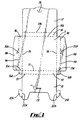
- a blank for forming a document holder or wallet is of one piece construction and preferably formed from polypropylene or other flexible plastics material, but may be formed from flexible card or board.
- the blank incorporates a central or back panel 5 adapted to form the back of the assembled holder.
- side panels 6A and 6B are connected by fold lines 7A and 7B to opposite sides of the back panel 5 and attachment panels 8A and 8B are attached by fold lines 9A and 9B to the respective outer edges of the side panels 6A and 6B.
- a relatively narrow bottom panel 10 is connected by a fold line 11 to the lower edge of the back panel 5 and a front panel 12 is hingedley connected by a fold line 13 to the outer edge of the bottom panel 10.
- a pair of tabs 14A and 14B are connected by fold lines 15A and 15B to the lower edges of the respective side panels 6A and 6B and lie alongside but are not connected to opposite ends of the bottom panel 10.
- a top panel 16 is connected by a fold line 16A to the upper edge of the back panel 5 and a closure flap 17 is connected by a fold line 17A to the outer edge of the top panel 16.
- a tab 18 is formed adjacent the free outer edge of the closure flap 17 and cooperates, when the holder is assembled, with a slot 19 formed adajacent the outer edge of the front panel 12 to enable the assembled holder to be opened and closed to gain access to documents or other items which may be contained in it.
- Apertures 20A and 20B are provided in the respective attachment panels 8A and 8B and are adapted in use to be engaged by projecting tongue members 21A and 21B connected by fold lines 22A and 22B to the opposite side edges of the front panel 12 adjacent the outer end thereof to maintain the holder in its assembled position as will be described hereafter.
- the holder is formed from the blank of Fig. 1 by first folding the tabs 14A and 14B inwardly about the folds lines 15A and 15B and then folding the side panels 6A,6B, the bottom panel 10 and the top panel 16 inwardly about the respective fold lines 7A, 7B, 11 and 16A.
- the attachment panels 8A and 8B are then folded inwardly about the fold lines 9A and 9B so as to lie parallel to the backpanel 5.
- the front panel 12 is then folded inwardly about the fold line 13 to a position in which it lies flush against the attachment panels 8A and 8B. These then require to be interconnected by engagement of the tongues 21A and 21B in the respective apertures 20A and 20B as will be described below.
- This retains the folder in the assembled condition illustrated in Fig. 3 and the closure flap 17 may then be pivotted about the fold line 17A and the tab 18 engaged in and released from the slot 19 as required to close and open the folder to gain access to the contents.
- Each of the locking apertures 20A,20B is of generally triangular form having two relatively long sides 25 and 26 interconnected by a relatively short third side or base 27.
- Side 25 is shorter than side 26 and is aligned with the fold line 9A.
- the relatively longer side 26 is inclined outwardly towards the free edge of the associated attachment panel so that when the attachment panel is folded into its assembled position as shown in Fig. 2, the side 26 of the opening 20A is displaced inwardly from the associated side wall panel 6A.
- the sides 25 and 26 of the aperture are straight whereas the relatively short base 27 is inwardly curved to define recesses 28A and 28B at the two bottom corners of the triangular aperture.
- Each of the tongues 21A,21B is attached to the associated side edge of the front panel by a neck portion 30 the length of which corresponds approximately to that of the side 25 of the aperature 20A.
- a nose portion 31 is set back from the neck 30 of the tongue and extends parallel thereto to define a slot 32 between the nose portion 31 and the adjacent edge of the front panel 12.
- the tongue extends outwardly from the opposite end of the neck portion 30 to define a tail 33 projecting in the opposite direction from the nose portion 31, the outer edge 33A of the tail portion 33 extending generally parallel to the neck 30 and the outer edge 31A of the nose portion 31 being of arcuate form.
- the distance between the end of the neck 30 adjacent the tail 33 and the tip of the nose portion 31 corresponds approximately to the length of the longer side 26 of the recess 20A.
- the relationship between the tongue 21A and the associated recess 20A is such that the tongue cannot be inserted into the recess except adjacent the longer edge 26 and then only if the front panel is deformed as shown at 35 in Fig. 2 to permit the tail 33 of the tongue to enter the recess first.
- the tongue may then be moved inwardly until point 30A rests in the notch 28B of the recess 20A at which point the tongue may be rotated about point 30A until the tip 31B of the nose 31 passes into the recess at its apex. This movement is permitted by virtue of the curved outer surface 31A of the tongue and the fact that the distance between points 30A and 31B corresponds to the length of the longest side 26 of the recess.
- the tongue is located within the holder, the front panel of which lies generally flush with the associated attachment panel but with the tongue lying generally parallel to the edge 26 of the recess 20A.
- the tongue may then be moved from this engaging position into a locking position by applying lateral pressure from within the holder to force the corner 30A to ride over the curved portion of the base 27 of the recess from the notch 28B into the notch 28A.
- the nose 31 projects beyond the upper edge of the recess and the tail 33 beyond the lower edge with the tongue lying flat against the inner surface of the side wall panel 6A. It is not then possible by pulling on the front panel to disengage it from the body of the holder and the holder is thus securely held in its assembled condition.
- the tongues 21A and 21B at opposite sides of the holder require to be moved inwardly to lie along the longer side 26 of the respective recesses, following which the tongues may be withdrawn from the recesses by reversing the movement effected to engage them initially.
- each tongue 21A,21B that is to say the dimension at right angles to the associated fold line 22A,22B is approximately equal to the width of the side walls 6A,6B.
- the cooperating parts of the latch means may be readily engaged with one another in the engaging position but rather than remaining there, the tongues are moved bodily outwardly into their locking positions in which they lie flush against the side walls of the assembled holder. In this position the assembly is securely locked in its assembled position and cannot inadvertantly come apart causing spillage or loss of the contents.
- the latch means may also be disengaged if required by first moving the tongues into the engaging position and then withdrawing them from the respective apertures, although it will be appreciated that in general disengagement is infrequently required.
- the principal benefit of the construction resides in the fact that it may be transported and stored as a flat blank taking up minimum space and once assembled the holder will generally not require to be taken apart subsequently.
- the location of the tongues adjacent the side wall panels of the assembed holder is also advantageous in that they do not interefere with documents being placed into or removed from the holder and even if such documents contact the tongues, it is not possible for them to effect disengagement of the tongues from the associated recesses.
- the triangular recesses have their apices uppermost, they could be inverted if desired.
- the shape, size and dimensions of the tongues and the recesses may also be varied provided they afford an initial engaging position and a subsequent locking position in which it is not possible for the tongues to be withdrawn from the recesses.
- the use of the tongues to rigidify the assembled holder in the manner aforesaid may be incorporated in a holder not provided with a dual position locking movement and alternative forms of latch means operable to rigidify the assembled holder may be employed if desired.
- the wallet or holder is formed from plastics material it could alternatively be formed from cardboard or other similar material.
Landscapes
- Purses, Travelling Bags, Baskets, Or Suitcases (AREA)
Applications Claiming Priority (2)
| Application Number | Priority Date | Filing Date | Title |
|---|---|---|---|
| GB9610816A GB2313342B (en) | 1996-05-23 | 1996-05-23 | Document holders |
| GB9610816 | 1996-05-23 |
Publications (2)
| Publication Number | Publication Date |
|---|---|
| EP0808724A1 true EP0808724A1 (fr) | 1997-11-26 |
| EP0808724B1 EP0808724B1 (fr) | 2001-10-10 |
Family
ID=10794206
Family Applications (1)
| Application Number | Title | Priority Date | Filing Date |
|---|---|---|---|
| EP19970303537 Expired - Lifetime EP0808724B1 (fr) | 1996-05-23 | 1997-05-23 | Porte-documents |
Country Status (3)
| Country | Link |
|---|---|
| EP (1) | EP0808724B1 (fr) |
| DE (1) | DE69707199T2 (fr) |
| GB (2) | GB2313342B (fr) |
Cited By (2)
| Publication number | Priority date | Publication date | Assignee | Title |
|---|---|---|---|---|
| DE19900108C1 (de) * | 1999-01-05 | 2000-05-04 | Dataplus Gmbh | Umlaufend schließbarer Ordner zur Schriftgutaufbewahrung |
| WO2016020574A1 (fr) * | 2014-08-07 | 2016-02-11 | KADRIC, Sanela | Portefeuille |
Families Citing this family (3)
| Publication number | Priority date | Publication date | Assignee | Title |
|---|---|---|---|---|
| US6354486B1 (en) * | 2000-10-16 | 2002-03-12 | Chin-Lien Ho | Expansible document holder |
| GB2418200A (en) * | 2004-09-17 | 2006-03-22 | Bantex Ltd | Storage box |
| GB2479395B (en) * | 2010-04-08 | 2012-03-07 | James C Huang | A dual-purpose file folder |
Citations (3)
| Publication number | Priority date | Publication date | Assignee | Title |
|---|---|---|---|---|
| FR2502066A1 (fr) * | 1981-03-19 | 1982-09-24 | Achats Distr Articles Classeme | Perfectionnement aux chemises |
| GB2232071A (en) * | 1989-04-28 | 1990-12-05 | Easibind Ltd | Wallets |
| GB2276126A (en) * | 1993-03-17 | 1994-09-21 | Thomas Simon Corbishley | Document folder. |
Family Cites Families (5)
| Publication number | Priority date | Publication date | Assignee | Title |
|---|---|---|---|---|
| NZ217923A (en) * | 1985-10-19 | 1988-11-29 | Easibind Ltd | Blank, erectable into document folder |
| GB2217264A (en) * | 1988-03-04 | 1989-10-25 | Easibind Ltd | Document wallet |
| GB2227457A (en) * | 1988-12-03 | 1990-08-01 | Easibind Ltd | Document wallet |
| GB2274813B (en) * | 1993-02-03 | 1996-03-06 | Folders Galore Ltd | A document file |
| GB9416718D0 (en) * | 1994-08-18 | 1994-10-12 | Acco Rexel Group Services Plc | Imporovements in or relating to a document-holder |
-
1996
- 1996-05-23 GB GB9610816A patent/GB2313342B/en not_active Expired - Fee Related
-
1997
- 1997-05-23 GB GB9710546A patent/GB2314807B/en not_active Expired - Fee Related
- 1997-05-23 DE DE1997607199 patent/DE69707199T2/de not_active Expired - Fee Related
- 1997-05-23 EP EP19970303537 patent/EP0808724B1/fr not_active Expired - Lifetime
Patent Citations (3)
| Publication number | Priority date | Publication date | Assignee | Title |
|---|---|---|---|---|
| FR2502066A1 (fr) * | 1981-03-19 | 1982-09-24 | Achats Distr Articles Classeme | Perfectionnement aux chemises |
| GB2232071A (en) * | 1989-04-28 | 1990-12-05 | Easibind Ltd | Wallets |
| GB2276126A (en) * | 1993-03-17 | 1994-09-21 | Thomas Simon Corbishley | Document folder. |
Cited By (2)
| Publication number | Priority date | Publication date | Assignee | Title |
|---|---|---|---|---|
| DE19900108C1 (de) * | 1999-01-05 | 2000-05-04 | Dataplus Gmbh | Umlaufend schließbarer Ordner zur Schriftgutaufbewahrung |
| WO2016020574A1 (fr) * | 2014-08-07 | 2016-02-11 | KADRIC, Sanela | Portefeuille |
Also Published As
| Publication number | Publication date |
|---|---|
| EP0808724B1 (fr) | 2001-10-10 |
| GB9710546D0 (en) | 1997-07-16 |
| GB9610816D0 (en) | 1996-07-31 |
| DE69707199T2 (de) | 2002-06-20 |
| GB2313342A (en) | 1997-11-26 |
| GB2314807A8 (en) | 1998-05-05 |
| DE69707199D1 (de) | 2001-11-15 |
| GB2314807B (en) | 2000-09-13 |
| GB2314807A (en) | 1998-01-14 |
| GB2313342B (en) | 2000-10-25 |
Similar Documents
| Publication | Publication Date | Title |
|---|---|---|
| US6666610B1 (en) | Folder | |
| US5275331A (en) | Foldable container with one-step unfolding operation | |
| CA2791601C (fr) | Decoupe et contenant ayant un mecanisme anti-derobement | |
| US4516718A (en) | Carton with automatic lock | |
| US5363959A (en) | Brush keepers | |
| AU757239B2 (en) | Slash jacket with a retractable attachment member | |
| US5398868A (en) | Foldable knock-down storage box with detachable hingeable cover | |
| EP0666218B1 (fr) | Flan pour l'obtention d'une caisse américaine à ouverture facile et caisse ainsi obtenue | |
| US4236740A (en) | File box | |
| US4511079A (en) | Variable dimension container | |
| US9278774B2 (en) | Clamshell carton with locking tab | |
| US5799864A (en) | Container closure arrangement | |
| US4311268A (en) | Footwear box with handles | |
| US2199204A (en) | Display box | |
| EP0808724B1 (fr) | Porte-documents | |
| US3182792A (en) | Dispenser carton | |
| EP0220874B2 (fr) | Porte-documents | |
| GB2127786A (en) | Food scoop | |
| GB2217264A (en) | Document wallet | |
| US3853260A (en) | Bellows fold end closure | |
| US1755690A (en) | Foldable box | |
| US5791556A (en) | Easy opening envelope | |
| GB2232071A (en) | Wallets | |
| US20150291304A1 (en) | Tab lock closure for a container | |
| GB2227457A (en) | Document wallet |
Legal Events
| Date | Code | Title | Description |
|---|---|---|---|
| PUAI | Public reference made under article 153(3) epc to a published international application that has entered the european phase |
Free format text: ORIGINAL CODE: 0009012 |
|
| AK | Designated contracting states |
Kind code of ref document: A1 Designated state(s): BE DE FR GB IE NL |
|
| 17P | Request for examination filed |
Effective date: 19980519 |
|
| 17Q | First examination report despatched |
Effective date: 19990420 |
|
| GRAG | Despatch of communication of intention to grant |
Free format text: ORIGINAL CODE: EPIDOS AGRA |
|
| RTI1 | Title (correction) |
Free format text: DOCUMENT HOLDER |
|
| GRAG | Despatch of communication of intention to grant |
Free format text: ORIGINAL CODE: EPIDOS AGRA |
|
| GRAG | Despatch of communication of intention to grant |
Free format text: ORIGINAL CODE: EPIDOS AGRA |
|
| GRAH | Despatch of communication of intention to grant a patent |
Free format text: ORIGINAL CODE: EPIDOS IGRA |
|
| GRAH | Despatch of communication of intention to grant a patent |
Free format text: ORIGINAL CODE: EPIDOS IGRA |
|
| GRAA | (expected) grant |
Free format text: ORIGINAL CODE: 0009210 |
|
| AK | Designated contracting states |
Kind code of ref document: B1 Designated state(s): BE DE FR GB IE NL |
|
| REG | Reference to a national code |
Ref country code: IE Ref legal event code: FG4D |
|
| REF | Corresponds to: |
Ref document number: 69707199 Country of ref document: DE Date of ref document: 20011115 |
|
| REG | Reference to a national code |
Ref country code: GB Ref legal event code: IF02 |
|
| ET | Fr: translation filed | ||
| PGFP | Annual fee paid to national office [announced via postgrant information from national office to epo] |
Ref country code: IE Payment date: 20020515 Year of fee payment: 6 |
|
| PGFP | Annual fee paid to national office [announced via postgrant information from national office to epo] |
Ref country code: BE Payment date: 20020611 Year of fee payment: 6 |
|
| PLBE | No opposition filed within time limit |
Free format text: ORIGINAL CODE: 0009261 |
|
| STAA | Information on the status of an ep patent application or granted ep patent |
Free format text: STATUS: NO OPPOSITION FILED WITHIN TIME LIMIT |
|
| 26N | No opposition filed | ||
| PG25 | Lapsed in a contracting state [announced via postgrant information from national office to epo] |
Ref country code: IE Free format text: LAPSE BECAUSE OF NON-PAYMENT OF DUE FEES Effective date: 20030523 |
|
| PG25 | Lapsed in a contracting state [announced via postgrant information from national office to epo] |
Ref country code: BE Free format text: LAPSE BECAUSE OF NON-PAYMENT OF DUE FEES Effective date: 20030531 |
|
| BERE | Be: lapsed |
Owner name: *DURAWELD LTD Effective date: 20030531 |
|
| REG | Reference to a national code |
Ref country code: IE Ref legal event code: MM4A |
|
| PGFP | Annual fee paid to national office [announced via postgrant information from national office to epo] |
Ref country code: DE Payment date: 20070515 Year of fee payment: 11 |
|
| PGFP | Annual fee paid to national office [announced via postgrant information from national office to epo] |
Ref country code: NL Payment date: 20080531 Year of fee payment: 12 |
|
| PG25 | Lapsed in a contracting state [announced via postgrant information from national office to epo] |
Ref country code: DE Free format text: LAPSE BECAUSE OF NON-PAYMENT OF DUE FEES Effective date: 20081202 |
|
| PGFP | Annual fee paid to national office [announced via postgrant information from national office to epo] |
Ref country code: FR Payment date: 20090423 Year of fee payment: 13 |
|
| NLV4 | Nl: lapsed or anulled due to non-payment of the annual fee |
Effective date: 20091201 |
|
| PG25 | Lapsed in a contracting state [announced via postgrant information from national office to epo] |
Ref country code: NL Free format text: LAPSE BECAUSE OF NON-PAYMENT OF DUE FEES Effective date: 20091201 |
|
| REG | Reference to a national code |
Ref country code: FR Ref legal event code: ST Effective date: 20110131 |
|
| PG25 | Lapsed in a contracting state [announced via postgrant information from national office to epo] |
Ref country code: FR Free format text: LAPSE BECAUSE OF NON-PAYMENT OF DUE FEES Effective date: 20100531 |
|
| PGFP | Annual fee paid to national office [announced via postgrant information from national office to epo] |
Ref country code: GB Payment date: 20160629 Year of fee payment: 20 |
|
| REG | Reference to a national code |
Ref country code: GB Ref legal event code: PE20 Expiry date: 20170522 |
|
| PG25 | Lapsed in a contracting state [announced via postgrant information from national office to epo] |
Ref country code: GB Free format text: LAPSE BECAUSE OF EXPIRATION OF PROTECTION Effective date: 20170522 |