EP0809011A2 - Schubvectorsteuerung für Bläsertriebwerke - Google Patents
Schubvectorsteuerung für Bläsertriebwerke Download PDFInfo
- Publication number
- EP0809011A2 EP0809011A2 EP97108028A EP97108028A EP0809011A2 EP 0809011 A2 EP0809011 A2 EP 0809011A2 EP 97108028 A EP97108028 A EP 97108028A EP 97108028 A EP97108028 A EP 97108028A EP 0809011 A2 EP0809011 A2 EP 0809011A2
- Authority
- EP
- European Patent Office
- Prior art keywords
- altering
- engine
- flow
- thrust
- vanes
- Prior art date
- Legal status (The legal status is an assumption and is not a legal conclusion. Google has not performed a legal analysis and makes no representation as to the accuracy of the status listed.)
- Withdrawn
Links
Images


Classifications
-
- F—MECHANICAL ENGINEERING; LIGHTING; HEATING; WEAPONS; BLASTING
- F02—COMBUSTION ENGINES; HOT-GAS OR COMBUSTION-PRODUCT ENGINE PLANTS
- F02K—JET-PROPULSION PLANTS
- F02K1/00—Plants characterised by the form or arrangement of the jet pipe or nozzle; Jet pipes or nozzles peculiar thereto
- F02K1/54—Nozzles having means for reversing jet thrust
- F02K1/64—Reversing fan flow
- F02K1/70—Reversing fan flow using thrust reverser flaps or doors mounted on the fan housing
- F02K1/72—Reversing fan flow using thrust reverser flaps or doors mounted on the fan housing the aft end of the fan housing being movable to uncover openings in the fan housing for the reversed flow
-
- F—MECHANICAL ENGINEERING; LIGHTING; HEATING; WEAPONS; BLASTING
- F02—COMBUSTION ENGINES; HOT-GAS OR COMBUSTION-PRODUCT ENGINE PLANTS
- F02K—JET-PROPULSION PLANTS
- F02K1/00—Plants characterised by the form or arrangement of the jet pipe or nozzle; Jet pipes or nozzles peculiar thereto
- F02K1/002—Plants characterised by the form or arrangement of the jet pipe or nozzle; Jet pipes or nozzles peculiar thereto with means to modify the direction of thrust vector
- F02K1/008—Plants characterised by the form or arrangement of the jet pipe or nozzle; Jet pipes or nozzles peculiar thereto with means to modify the direction of thrust vector in any rearward direction
-
- F—MECHANICAL ENGINEERING; LIGHTING; HEATING; WEAPONS; BLASTING
- F02—COMBUSTION ENGINES; HOT-GAS OR COMBUSTION-PRODUCT ENGINE PLANTS
- F02K—JET-PROPULSION PLANTS
- F02K1/00—Plants characterised by the form or arrangement of the jet pipe or nozzle; Jet pipes or nozzles peculiar thereto
- F02K1/54—Nozzles having means for reversing jet thrust
- F02K1/64—Reversing fan flow
- F02K1/68—Reversers mounted on the engine housing downstream of the fan exhaust section
-
- F—MECHANICAL ENGINEERING; LIGHTING; HEATING; WEAPONS; BLASTING
- F02—COMBUSTION ENGINES; HOT-GAS OR COMBUSTION-PRODUCT ENGINE PLANTS
- F02K—JET-PROPULSION PLANTS
- F02K1/00—Plants characterised by the form or arrangement of the jet pipe or nozzle; Jet pipes or nozzles peculiar thereto
- F02K1/54—Nozzles having means for reversing jet thrust
- F02K1/64—Reversing fan flow
- F02K1/70—Reversing fan flow using thrust reverser flaps or doors mounted on the fan housing
-
- F—MECHANICAL ENGINEERING; LIGHTING; HEATING; WEAPONS; BLASTING
- F02—COMBUSTION ENGINES; HOT-GAS OR COMBUSTION-PRODUCT ENGINE PLANTS
- F02K—JET-PROPULSION PLANTS
- F02K1/00—Plants characterised by the form or arrangement of the jet pipe or nozzle; Jet pipes or nozzles peculiar thereto
- F02K1/54—Nozzles having means for reversing jet thrust
- F02K1/74—Reversing at least one flow in relation to at least one other flow in a plural- flow engine
-
- Y—GENERAL TAGGING OF NEW TECHNOLOGICAL DEVELOPMENTS; GENERAL TAGGING OF CROSS-SECTIONAL TECHNOLOGIES SPANNING OVER SEVERAL SECTIONS OF THE IPC; TECHNICAL SUBJECTS COVERED BY FORMER USPC CROSS-REFERENCE ART COLLECTIONS [XRACs] AND DIGESTS
- Y02—TECHNOLOGIES OR APPLICATIONS FOR MITIGATION OR ADAPTATION AGAINST CLIMATE CHANGE
- Y02T—CLIMATE CHANGE MITIGATION TECHNOLOGIES RELATED TO TRANSPORTATION
- Y02T50/00—Aeronautics or air transport
- Y02T50/60—Efficient propulsion technologies, e.g. for aircraft
Definitions
- the present invention relates to mechanisms for altering the thrust produced by turbo-fan engines, and more particularly to multi-axis thrust vectoring devices incorporated into the nacelle of an aircraft for augmenting control of the craft while reducing overall weight, lowering fuel burn, reducing maintenance and improving safety.
- Mechanisms for accomplishing engine thrust reversal have been known for some time.
- Various designs have been implemented, including cascade vanes, deployable doors to turn air flow, and blocker doors to divert air flow.
- thrust vectoring principles on future aircraft could yield even greater benefits.
- a fully integrated thrust vectoring flight control system will enable designers to eliminate or significantly reduce the conventional horizontal and/or vertical control surfaces now used to control conventional aircraft. This will translate into substantial weight and cost savings due to reduction of the number of produced components and their respective controls, as well as lower drag levels.
- Another object of the present invention is to provide a multi-axis thrust vectoring apparatus which is incorporated into an aircraft's engine nacelle for controlling the direction of thrust generated by the engines so that flight behavior of the entire aircraft can be altered by appropriate manipulations of the thrust vector apparatus.
- thrust reversing apparatus for diverting air flowing through an engine nacelle from pure rearward flow to a combination of rearward and radially outward flow, and then to a combination of various radially outward angles and forward flow, where in the latter state thrust reversal is effected.
- the apparatus comprises inner and outer air flow blocking members disposed parallel to one another in the nacelle housing and driven by actuators coupled to the two blocking members for effecting their synchronous movement.
- the inner blocking member which includes a first door having fixed vanes and a solid second door pivotably coupled to the first door, has a closed position in which the two doors are collinear and various open positions in which the two doors are pivoted relative to one another out of the collinear relationship.
- the outer blocking member which comprises an array of pivotable, parallel vanes, has a closed position in which the vanes overlap and are tightly secured against one another and various open positions in which the vanes are continuously pivotable out of contact with one another through various amounts of rotation from a first position in which the air flow is directed predominantly rearwardly to any one of several progressively more open positions.
- the vanes may be rotated to a second position in which the air flow is directed rearwardly and radially outwardly, then to a third position in which the air flow is directed predominantly radially outwardly, then to a fourth position in which the air flow is directed radially outwardly and forwardly, and then to still another position in which the air flow is directed predominantly forwardly.
- the thrust reversing apparatus is actuated, and then the outer and inner blocking members move in synchronicity with each other as described above to achieve one or more of the thrust diverting positions effected by the combined movement of the two air flow blocking members together.
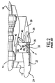
- Figure 1 of the drawing illustrates one example of an engine thrust reverser mechanism well-known in the art.
- the engine shown in Figure 1 is a turbo-fan engine, and it will be noted that the top portion of the drawing shows the thrust reverser mechanism in a closed, inoperative, position, while the bottom portion of the drawing shows the thrust reverser mechanism in an open, operative, position.
- the elements shown in the top and bottom drawing portions are the same; however, they are depicted as being positioned in different locations or orientations as a result of the state of operativeness of the thrust reverser mechanism.
- the engine 10 includes a fan 12, a compressor 14, and a turbine 16.
- the fan is at the inlet 22 of the engine, the compressor is located in the forward region of the engine, and the turbine is located at the exhaust region 18 of the engine.
- Fan casing 20, which surrounds the fan of the engine, includes the inlet 22, a fixed cowl 24, a movable cowl 26, and a thrust reversing assembly 30.
- the thrust reversing assembly 30, shown in greater detail in Figure 2 includes a piston cylinder 32, a piston rod 33, linkage 34, thrust reversing element 35 (to be described in greater detail below) and an internal cavity 36 in the movable cowl 26 for housing and preventing operation of the thrust reversing element when the fixed and movable cowls 24, 26 are disposed in the inoperative position seen in the upper portion of the engine in Figure 1.
- FIG. 1 The lower portion of Figure 1 shows the fixed cowl 24 and the movable cowl 26 disposed in a second position.
- the piston cylinder 32 is secured to the fixed cowl member 24, and one end of the piston rod 33 is carried by the piston cylinder 32 while the other end of piston rod 33 is secured to the movable cowl member 26.
- the thrust reversing element 35 attached between the fixed cowl 24 and the movable cowl 26, becomes fully exposed when the cowls are caused to separate by extension of the piston rod 33 relative to the piston 32.
- An air blocking door 40 has one end pivotally attached to the movable cowl 26 and its opposite end pivotally attached to the linkage 34.
- Linkage 34 is pivotally attached between the door 40 and the engine compressor fairing at 42.
- Travel of door 40 to the operative position is effected by actuation of the piston rod 33 rearwardly to move the cowl 26 rearwardly and expose the thrust reversing element 35.
- the linkage 34 pivots rearwardly about its connection 42 to the engine compressor fairing, pulling the blocker door 40 away from the cowl 26 toward the engine compressor fairing so that the blocker door effectively blocks the path of air flowing through the engine airpath 50.
- the air now entering the engine through inlet 22 is forced to change direction and exit the airpath upstream of the cowl 26 at the thrust reversing member 35 now exposed between the cowls 24 and 26.
- the air is caused to exit the airpath 50 with a forwardly directed component F due to the angular orientation of the openings in the thrust reversing member 35.
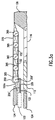
- Figures 3-5 show a first embodiment of the thrust vectoring assembly 100 embraced by the present invention.
- the present invention contemplates integrally incorporating one or more of the thrust vectoring assemblies into an engine nacelle, with the thrust vectoring assemblies being arranged circumferentially about the engine turbine and compressor sections at the rearward region of the engine nacelle.
- the present invention further contemplates the placement of such thrust vectoring mechanisms in each engine nacelle of the aircraft, with these thrust vectoring mechanisms operating in conjunction with each other to effect aircraft attitude, pitch and yaw control.
- each thrust vectoring assembly 100 is disposed between the forward and rearward cowl sections 124 and 126. These sections correspond to the fixed and movable cowl sections 24 and 26 of the thrust reversing mechanism 30 of the prior art (shown in Figures 1 and 2), but in the present invention are physically related and integrated as a single, structural assembly.
- cowl sections 124 and 126 are designed to be separated at the outset, with attainment of thrust vectoring being controlled by actuation of the elements one or more of the thrust vectoring assemblies.
- the thrust vectoring assembly 100 of the invention includes two members which together alter the air flowing through the engine: a first, inner, airflow blocking member 110 and a second, outer, airflow direction altering member 150 arranged substantially parallel to the first member. Both the first and second members are disposed in and extend across the separation between the forward cowl section 124 and the rearward cowl section 126.
- the second member 150 includes pivotable vanes or louvers 152, the endmost of which have edge portions that engage against adjacent edges of the cowl sections such that the edge portions effectively act as seals for effectively preventing fluid flow between the ambient air A and the engine flow path air FP (shown in Figure 3 by the arrow) when the first and second members are in an inoperative position, as shown in Figure 3.
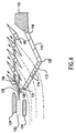
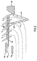
- the first and second members function together to alter the direction of air flowing through and about the engine fairing between a first state (illustrated in Figure 3) in which the flow is solely along and about the engine fairing, a second state (illustrated in Figure 4) in which the flow is partially deflected radially outwardly of the engine by a slight intrusion of the first member into the engine air flow path and a slight rotation of the pivotable vanes 152 of the second member (counter clockwise) toward the outside of the engine nacelle, and a third state (illustrated in Figure 5) in which the flow is substantially entirely diverted from the engine flow path and directed radially outwardly and forwardly of the engine (see discussion below for more details), thereby producing a forwardly-directed, craft reversing, force.
- a first state illustrated in Figure 3
- a second state illustrated in Figure 4
- the flow is partially deflected radially outwardly of the engine by a slight intrusion of the first member into the engine air flow path and a slight
- the first member 110 comprises a first segment 112 bearing a plurality of vanes 114 oriented at about 45 degrees to the longitudinal axis of the engine (generally parallel to the flowpath FP), and a second, solid segment 116 having a length which is substantially equal to the length of the first segment.
- the rearward end of the second segment is supported on the rearward cowl section 126 at a pivot 118.
- the forward end of the second segment is connected via pivot 120 to the rearward end of the first segment 112.
- the pivot 120 is constructed so as to only permit inward movement of the pivot 120 toward the engine fairing, as shown in Figures 4 and 5.
- the forward end of the first segment is connected via pivot 122 to a linkage 128 which, in turn, is rigidly connected to the piston rod 129 at connection point 130.
- the piston rod 129 is connected to a piston 132 disposed within the forward cowl section 124 adjacent the rearward portion thereof. The operation of the piston rod 129 will be described in more detail below.
- the second member 150 includes a set of pivotable louvers 152, which are connected together via appropriate linkage so as to be pivoted simultaneously about pivots 156. In the preferred embodiment shown in Figures 3-5, all of the louvers 152 pivot with the same degree of rotation.
- a linkage 159 has one end connected to the set of louvers, preferably to the forwardmost louver 152a at a connection point 160, and the other end connected to a second actuator (not shown) which travels in tandem with (adjacent and next to) the rod 129, but through a distance proportionate with the distance travelled by the rod 129, so that the first and second members are each piston driven by their respective piston rods between first, second, and third, positions.
- louver driving means is shown in Figure 3a to include a piston rod 329 having gear teeth 329' extending along the length thereof, and a wheel gear 359 (which replaces the linkage 159) coupled to the louvers (at 152a) to drive the latter in rotation about their pivot axes 360.
- Each of the louvers have a gear 365 located at their pivot axes which has a diameter smaller than the diameter of the gear 359.
- a "timing" chain or belt 370 engages and is driven by reduction gear 359' on the rear of gear 359.
- the teeth of gears 365 engage teeth on the belt or notches in the chain. Linear motion of the piston rod 329 is thus converted to a desired rotational movement of the gears 359, 360 and hence rotation of the louvers.
- the forward end of the first segment 112 of the member 110 is connected via pivot 122 to linkage 128 which, in turn, is rigidly connected to the piston rod 329 at connection point 130.
- the first position (see Figure 3) is an inoperative position, where the piston 132 has not been actuated so that the piston rod 130 is held in its retracted position.
- the facing sides of adjacent louvers 152 are thus held in contact with one another so that the louvers are maintained substantially parallel to one another, and to the longitudinal axis of the engine, to effect a closed wall between the forward cowl section 124 and the rearward cowl section 126.
- the second position is a position in which the set of louvers become partially operative to divert air, flowing through the engine flow path, in such a manner as to effect thrust reduction.
- louvers 152 are rotated about pivots 156 so that the forward portions of the louvers are positioned radially inwardly toward the longitudinal axis of the engine, while the rearward portions of the louvers are rotated outwardly of the engine longitudinal axis. It is to be noted, however, that throughout their rotation, all the louvers maintain their parallel relationship to one another.
- the third position is a position in which the louvers become fully operative to divert engine thrust forwardly.
- the louvers have been further rotated (counter clockwise) about their pivots 156 such that the once rearwardly directed portions of the louvers are now directed forwardly.
- the solid segment 116 of the member 110 located immediately radially inwardly of the set of vanes, is caused to fold inwardly toward the turbine section of the engine. In the inwardly folded position, the solid segment 116 blocks rearward flow of engine air and forces the flow to turn and flow in a forwardly oriented direction.
- FIG. 3-5 combines the forward cowl and the fan reverser into one single, movable, structural component. This not only enhances the structural integrity of the nacelle, but also provides integration of the air flow blocking segments and their linkages into a fixed fan cowl assembly, thus enabling a reduction in weight as well as increased reliability and maintainability.
- the diverter door is the functional equivalent of the door and hinge assembly shown in Figure 1, and is composed of a forward cascade assembly including vanes 114, and a solid, non-porous, panel 116 aft of the hinge 120.
- fan flow first passes between the engine fairing and the cascade vane set 114, then between the engine fairing and the solid panel 116, and finally the flow exits the rear end of the nacelle in the conventional manner.
- the tight side-to-side sealing abutment of adjacent louvers of the outer member 150 and the edge portion seals of the endmost vanes 152 prevent appreciable leakage through the vane set 114, as well as the hinge and sides of the first member 110, when the latter is stowed in the inoperative position shown in Figure 3.
- the piston rod 129 is moved rearwardly a predetermined amount causing the forward end of the inner member 110 to translate rearwardly, while at the same time, the actuator connected to the first vane 152a also moves rearwardly.
- Such movement of these actuators (1) causes the vanes 152 of the outer member to rotate about the pivots 156 so that the rearward ends of the vanes move outwardly (in a counter clockwise motion as viewed in Figure 4), and (2) causes the second, inner member 110 to fold inwardly about the hinge 120 so that the door 116 partially blocks the flow of air in the engine core exhaust path (represented by the arrow FP), and forces the air through the partially open vane set of the outer member 150.
- the vanes of the outer member continue to be urged in rotation in a radially outwardly directed (counter-clockwise direction) manner by the continued rearward translation of the piston rod 130.
- the forward end of the inner member 110 begins to translate in a rearward direction, and the vane set and blocker door of the inner member begin to fold about the hinge 120 inwardly into the engine fan flow path FP.
- Increased aft translation of the inner member is a function of the thrust vectoring demand (more demand results in more movement) .
- the engine fan flow is channeled through the vane set, and in conjunction with the solid blocker door 116, causes the flow to exit out the louvers of the outer member.
- the solid panel 116 serves as a guide for directing the engine air flow to the louvers of the outer member, as well as providing a smooth transition surface for the undiverted flow in the flow path FP to minimize thrust coefficient losses during vectoring.
- the actuators for each of the inner and outer members translate from the partially operative position (shorn in Figure 4) to their rearwardmost position, causing the inner member to be substantially completely folded relative to the vaned member 112 such that the vaned member and the door member 116 delimit a "V" therebetween, and further causing the leading ends of the louvers of the outer member 110 to rotate further about their pivots 156 from the partially operative position shown in Figure 4 to more forwardly directed positions.
- the leading ends of the outer member louvers move through an angle of approximately 120° from the closed, inoperative position shown in Figure 1.
- the present invention contemplates placing each set of inner and outer thrust vectoring members 110 and 150 at several, equally spaced, locations about the circumference of each engine nacelle.
- the invention further contemplates actuating pairs or sets of thrust vectoring members in each thrust vectoring assembly located at each engine nacelle to effect thrust vectoring of the entire aircraft, or actuating the thrust vectoring assemblies located at, or associated with, more than one engine nacelle at a time, to effect thrust vectoring of the entire aircraft.
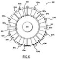
- the engine nacelle 600 viewed from the rear looking forwardly, with a circumferentially arranged set of actuators and deployable thrust vectoring assemblies.
- the engine nacelle includes a outer cowl 602, a plurality of circumferentially adjacent, deployable thrust vectoring vane assemblies 604a, 604b, 604c, 604d, 604e, 604f, 604g, 604h, an outer engine fairing 606, a core engine exhaust duct 608 which defines the engine flow path FP, and an inner engine fairing 610.
- Each of the thrust vectoring vane assemblies includes a plurality of individual louvers arranged in the manner shown in Figures 3-5.
- Figure 6 shows each louver set to number three (3); however, the invention contemplates using any number of louvers in a set.
- a connecting sleeve could be integrated into the geometry of the outer cowl, and two master actuators would be provided to drive eight slave actuators with digital clutching means to vary thrust vectoring and thrust reversing levels.
- the table in Figure 9 shows how various groups of actuators might be activated to achieve total aircraft control for three different conditions.
- the louvers in a set can be pivoted through various amounts of angular motion (see discussion regarding Figures 3-5) to achieve various degrees of thrust control.
- An "active" section is a set of vanes driven by an activated actuator.
- the first condition "Pitch up” results in the imposition of an upwardly directed force on the forward thrust component of the aircraft.
- actuation of thrust vectoring assemblies 604d and 604e is initiated, while at the same time, the inner airflow blocking member 110 is maintained in a closed position (as shown in Figure 3).
- four thrust vectoring assemblies 604c, 604d, 604e, and 604f are actuated such that the inner airflow blocking member is opened a slight bit, and the louvers open about 10°.
- thrust vectoring assemblies 604c, 604d, 604e, and 604f are actuated in such a manner that inner airflow blocking member is opened a moderate amount, and the louvers are opened about 45°.
- thrust vectoring assemblies 604c, 604d, 604e, and 604f are actuated such that the inner airflow blocking member is opened a maximum amount, and the louvers are opened about 90°.
- "Yaw left” is a condition in which a force having direction towards the left is imposed on the forward thrust component of the aircraft.
- the "Spoil” condition occurs when it is desired to keep the engine revved up, but to diminish or eliminate the forward thrust component. This condition typically is encountered or used when aircraft are approaching an aircraft carrier and are about to land (or not land) on the carrier's deck.
- the engine must be running at full power, but the forward thrust component of the engine must be eliminated so that the aircraft can either alight on the carrier deck (then the engine is shut down), or if such landing is thwarted, the forward thrust component is reinstated and the aircraft can immediately take off. In this condition, all flow of air directed to the rear through the engine must be blocked, and the flow must be directed radially outwardly instead.
- the "Spoil" condition might also be used in commercial flight where, on landing, thrust is spoiled to slow forward speed, and then on touch-down, the vanes are pivoted to effect a full reverse. With the engine still at full power, thrust reveral is easily attained without any delay associated with spooling up the engine.
- the first and eighth actuators (the “main actuators") 624a and 624h have been linked together via a splitter gearbox 630, providing dual redundancy.
- Each actuator has position sensing and clutching capabilities such that actuators may be operated independently of each other. This permits precision optimization of aircraft trim. Opening and closing the vanes will be controlled by the electronic engine control system of the aircraft. In cases where hydro-mechanical actuation is available, the aircraft flight control system will be used to control the vanes.
- Figures 8 and 9 show a second embodiment of the thrust vectoring apparatus of the present invention.
- the engine core cowl 820 supports the thrust vectoring apparatus 900, the latter being located downstream of the engine and the nacelle cowl 830.
- the apparatus includes a piston 910 having a piston rod 920 coupled to a linkage 930 which engages a first, upstream end of a movable door 940 (the door in its displaced position is shown at 940').
- a second door 950 (the displaced position is shown at 950') has a downstream end pivotably attached to the engine core cowl, and an upstream end pivotably attached to the downstream end of the first door 940. Movement of the piston rod 920 in a downstream direction causes the downstream end of the first door and upstream end of the second door to be displaced away from the engine core fairing into the engine exhaust gas flow. The effect of this action is to cause boundary layer separation of the exhaust gas flow from the engine core fairing at a location upstream of its separation point under normal operating conditions, thus altering the thrust component produced by the engine. As shown, there are a plurality of such hinged doors located circumferentially about the periphery of the core fairing.
- Each set of hinged doors is physically coupled and responsive to a piston and its piston rod.
- various pairs of doors are actuated, via respective pistons and rods, to be introduced into the air flow. Air flow strikes, and passes over, the doors, and is directed away from the engine nacelle to create a net vectoring force.
- the hinged doors of the present invention do not create large recirculation (i.e., drag) regions behind the deflected doors.
- the invention relates to an apparatus for altering the direction of fluid flowing axially through a housing having a longitudinal axis, said housing having inner and outer walls and defining a conduit through which said fluid flows, said apparatus comprising:
Landscapes
- Engineering & Computer Science (AREA)
- Chemical & Material Sciences (AREA)
- Combustion & Propulsion (AREA)
- Mechanical Engineering (AREA)
- General Engineering & Computer Science (AREA)
- Structures Of Non-Positive Displacement Pumps (AREA)
- Wind Motors (AREA)
Applications Claiming Priority (2)
| Application Number | Priority Date | Filing Date | Title |
|---|---|---|---|
| US650583 | 1991-02-05 | ||
| US08/650,583 US5706649A (en) | 1995-04-03 | 1996-05-20 | Multi axis thrust vectoring for turbo fan engines |
Publications (2)
| Publication Number | Publication Date |
|---|---|
| EP0809011A2 true EP0809011A2 (de) | 1997-11-26 |
| EP0809011A3 EP0809011A3 (de) | 1999-10-06 |
Family
ID=24609485
Family Applications (1)
| Application Number | Title | Priority Date | Filing Date |
|---|---|---|---|
| EP97108028A Withdrawn EP0809011A3 (de) | 1996-05-20 | 1997-05-16 | Schubvectorsteuerung für Bläsertriebwerke |
Country Status (3)
| Country | Link |
|---|---|
| US (1) | US5706649A (de) |
| EP (1) | EP0809011A3 (de) |
| JP (1) | JPH1054300A (de) |
Cited By (7)
| Publication number | Priority date | Publication date | Assignee | Title |
|---|---|---|---|---|
| EP1558840A4 (de) * | 2002-10-11 | 2006-03-22 | Nordam Group Inc | Schubumkehrvorrichtung mit zweiflügeliger tür |
| WO2008045050A1 (en) * | 2006-10-12 | 2008-04-17 | United Technologies Corporation | Gas turbine engine with fan variable area nozzle, nacelle assembly and method of varying area of a fan nozzle |
| FR2907853A1 (fr) * | 2006-10-27 | 2008-05-02 | Snecma Sa | Tuyere d'ejection des gaz pour turbomachine a double flux ayant une section d'ejection ou de col variable par deploiement de creneaux |
| RU2425242C1 (ru) * | 2010-02-11 | 2011-07-27 | Федеральное государственное унитарное предприятие "Центральный институт авиационного моторостроения имени П.И. Баранова" | Устройство поворота вектора тяги турбореактивного двухконтурного двигателя |
| EP3045707A1 (de) * | 2015-01-14 | 2016-07-20 | The Boeing Company | Verfahren und vorrichtung zum variieren von umkehrschub, insbesondere von flugtriebwerken |
| US9932932B2 (en) | 2012-10-29 | 2018-04-03 | Rolls-Royce Deutschland Ltd & Co Kg | Aeroengine thrust reverser arrangement |
| US10018151B2 (en) | 2015-01-14 | 2018-07-10 | The Boeing Company | Methods and apparatus to vary reverse thrust of aircraft engines |
Families Citing this family (43)
| Publication number | Priority date | Publication date | Assignee | Title |
|---|---|---|---|---|
| US6318668B1 (en) | 1996-08-02 | 2001-11-20 | Allison Advanced Development Company | Thrust vectoring techniques |
| US6105901A (en) * | 1996-08-02 | 2000-08-22 | Allison Engine Co., Inc. | Thrust vectoring system |
| US5794432A (en) * | 1996-08-27 | 1998-08-18 | Diversitech, Inc. | Variable pressure and variable air flow turbofan engines |
| AUPQ078299A0 (en) * | 1999-06-04 | 1999-06-24 | Metzen Louvres Pty Limited | A louvre system |
| US6382559B1 (en) | 1999-08-13 | 2002-05-07 | Rolls-Royce Corporation | Thrust vectoring mechanism |
| US6259976B1 (en) | 1999-09-25 | 2001-07-10 | Jerome H. Lemelson | Fuzzy logic based emergency flight control with thrust vectoring |
| US6622472B2 (en) * | 2001-10-17 | 2003-09-23 | Gateway Space Transport, Inc. | Apparatus and method for thrust vector control |
| FR2835021B1 (fr) * | 2002-01-24 | 2004-04-16 | Snecma Moteurs | Ensemble d'actionnement a verins hydrauliques synchronises |
| US7174704B2 (en) * | 2004-07-23 | 2007-02-13 | General Electric Company | Split shroud exhaust nozzle |
| GB2437295B (en) * | 2006-04-20 | 2008-06-25 | Rolls Royce Plc | Aeroengine ventilation system |
| GB0608985D0 (en) * | 2006-05-06 | 2006-06-14 | Rolls Royce Plc | Aeroengine thrust reverser |
| US7836681B2 (en) * | 2006-06-13 | 2010-11-23 | Rolls-Royce Corporation | Mechanism for a vectoring exhaust nozzle |
| US7837142B2 (en) * | 2006-10-12 | 2010-11-23 | Aerion Corporation | Supersonic aircraft jet engine |
| EP2074320B1 (de) * | 2006-10-12 | 2013-06-26 | United Technologies Corporation | Gebläsedüsen-schubumkehrvorrichtung mit variablem querschnitt |
| WO2008045082A1 (en) * | 2006-10-12 | 2008-04-17 | United Technologies Corporation | Reduced take-off field length using variable nozzle |
| EP2074303B1 (de) * | 2006-10-12 | 2011-02-02 | United Technologies Corporation | Innenhaubenschaufelblatt für turbinentriebwerk |
| US8720182B2 (en) * | 2006-10-12 | 2014-05-13 | United Technologies Corporation | Integrated variable area nozzle and thrust reversing mechanism |
| US20080258016A1 (en) * | 2007-04-23 | 2008-10-23 | Gukeisen Robert L | Nacelle assembly without lower bi-fi splitter |
| US8201390B2 (en) * | 2007-12-12 | 2012-06-19 | Spirit Aerosystems, Inc. | Partial cascade thrust reverser |
| US8959889B2 (en) | 2008-11-26 | 2015-02-24 | The Boeing Company | Method of varying a fan duct nozzle throat area of a gas turbine engine |
| US8127532B2 (en) | 2008-11-26 | 2012-03-06 | The Boeing Company | Pivoting fan nozzle nacelle |
| US8459036B2 (en) * | 2008-12-26 | 2013-06-11 | Rolls-Royce Corporation | Aircraft nozzle having actuators capable of changing a flow area of the aircraft nozzle |
| FR2946094B1 (fr) * | 2009-06-02 | 2014-04-18 | Aircelle Sa | Inverseur de poussee pour nacelle de turboreacteur double flux. |
| FR2958688B1 (fr) * | 2010-04-09 | 2013-02-22 | Aircelle Sa | Ensemble propulsif pour aeronef muni de moyens d'inversion de poussee |
| FR2958910B1 (fr) * | 2010-04-20 | 2012-04-27 | Aircelle Sa | Nacelle pour moteur d'aeronef a tuyere de section variable |
| US9255546B2 (en) * | 2012-02-02 | 2016-02-09 | Spirit AreoSystems, Inc. | Cascade-style variable area fan duct nozzle |
| US9399951B2 (en) * | 2012-04-17 | 2016-07-26 | General Electric Company | Modular louver system |
| FR2992685B1 (fr) * | 2012-07-02 | 2016-05-27 | Aircelle Sa | Procede de commande d'une section de tuyere variable d'un aeronef |
| US9068532B2 (en) * | 2012-07-24 | 2015-06-30 | Rohr, Inc. | Translating sleeve thrust reverser with movable cascade |
| US9016040B2 (en) * | 2012-11-30 | 2015-04-28 | General Electric Company | Thrust reverser system with translating-rotating cascade and method of operation |
| US9206912B2 (en) * | 2013-01-23 | 2015-12-08 | The Boeing Company | Dual door fan air modulating valve |
| GB201314527D0 (en) * | 2013-08-14 | 2013-09-25 | Rolls Royce Deutschland | Thrust reverser unit |
| FR3037617B1 (fr) * | 2015-06-17 | 2019-06-28 | Safran Aircraft Engines | Conduit de veine de decharge d'une turbomachine comprenant une grille vbv a section variable et actionnement passif |
| FR3047522B1 (fr) * | 2016-02-04 | 2018-03-16 | Safran Aircraft Engines | Ensemble propulsif pour aeronef |
| GB2548085B (en) | 2016-02-29 | 2019-12-25 | Ge Aviation Systems Llc | A system and method for coordinating a propeller with an electronic engine control |
| FR3055669B1 (fr) * | 2016-09-05 | 2018-09-28 | Airbus Operations | Systeme d'inverseur de poussee limitant les perturbations aerodynamiques en configuration inactive |
| GB201807267D0 (en) * | 2018-05-03 | 2018-06-20 | Rolls Royce Plc | Louvre offtake arrangement |
| US11078871B2 (en) * | 2018-12-21 | 2021-08-03 | Rohr, Inc. | Thrust reverser system with cascades |
| GB201903465D0 (en) * | 2019-03-14 | 2019-05-01 | Rolls Royce Plc | Louvre system |
| FR3095676B1 (fr) * | 2019-05-03 | 2021-04-09 | Safran Aircraft Engines | Grille d’inverseur de poussée incluant un traitement acoustique |
| FR3107932B1 (fr) * | 2020-03-09 | 2022-08-12 | Safran Aircraft Engines | Sortie d’air de nacelle pour turboréacteur d’aéronef à double flux comprenant un dispositif de guidage pour favoriser une phase d’inversion de poussée |
| FR3115837B1 (fr) * | 2020-11-03 | 2025-09-19 | Safran Aircraft Engines | Ensemble pour turbomachine d’aeronef a double flux, l’ensemble etant equipe d’ailettes de decharge d’air pilotees en incidence |
| US12276238B2 (en) * | 2023-01-30 | 2025-04-15 | The Boeing Company | Multiple turn reverser with side turning vanes |
Family Cites Families (14)
| Publication number | Priority date | Publication date | Assignee | Title |
|---|---|---|---|---|
| US3134226A (en) * | 1960-09-29 | 1964-05-26 | Bristol Siddeley Engines Ltd | Jet propulsion nozzles |
| GB1127828A (en) * | 1966-06-29 | 1968-09-18 | Rolls Royce | Fan thrust reverser for jet propulsion plant |
| US3441219A (en) * | 1966-11-29 | 1969-04-29 | Thiokol Chemical Corp | Directional control apparatus for rocket motors |
| GB1247691A (en) * | 1968-08-08 | 1971-09-29 | Rolls Royce | Improvements in or relating to fan ducts for gas turbine ducted fan engines |
| US3815357A (en) * | 1971-01-28 | 1974-06-11 | Rohr Industries Inc | Thrust reversing apparatus |
| US3736750A (en) * | 1971-03-12 | 1973-06-05 | Rolls Royce | Power plant |
| US3739582A (en) * | 1972-04-13 | 1973-06-19 | Rohr Industries Inc | Thrust reversing apparatus |
| GB1418905A (en) * | 1972-05-09 | 1975-12-24 | Rolls Royce | Gas turbine engines |
| US3779010A (en) * | 1972-08-17 | 1973-12-18 | Gen Electric | Combined thrust reversing and throat varying mechanism for a gas turbine engine |
| US3829020A (en) * | 1973-06-13 | 1974-08-13 | Boeing Co | Translating sleeve variable area nozzle and thrust reverser |
| US4026105A (en) * | 1975-03-25 | 1977-05-31 | The Boeing Company | Jet engine thrust reverser |
| US4030291A (en) * | 1976-01-02 | 1977-06-21 | General Electric Company | Thrust reverser for a gas turbofan engine |
| US4760960A (en) * | 1987-05-22 | 1988-08-02 | United Technologies Corporation | Linkage for area controlled, thrust vectoring vane cascade |
| FR2681101B1 (fr) * | 1991-09-11 | 1993-11-26 | Hispano Suiza | Inverseur de poussee de turboreacteur a pilotage ameliore des nappes du flux inverse. |
-
1996
- 1996-05-20 US US08/650,583 patent/US5706649A/en not_active Expired - Fee Related
-
1997
- 1997-05-16 EP EP97108028A patent/EP0809011A3/de not_active Withdrawn
- 1997-05-19 JP JP9128598A patent/JPH1054300A/ja not_active Withdrawn
Cited By (9)
| Publication number | Priority date | Publication date | Assignee | Title |
|---|---|---|---|---|
| EP1558840A4 (de) * | 2002-10-11 | 2006-03-22 | Nordam Group Inc | Schubumkehrvorrichtung mit zweiflügeliger tür |
| WO2008045050A1 (en) * | 2006-10-12 | 2008-04-17 | United Technologies Corporation | Gas turbine engine with fan variable area nozzle, nacelle assembly and method of varying area of a fan nozzle |
| US8365515B2 (en) | 2006-10-12 | 2013-02-05 | United Technologies Corporation | Gas turbine engine with fan variable area nozzle, nacelle assembly and method of varying area of a fan nozzle |
| FR2907853A1 (fr) * | 2006-10-27 | 2008-05-02 | Snecma Sa | Tuyere d'ejection des gaz pour turbomachine a double flux ayant une section d'ejection ou de col variable par deploiement de creneaux |
| RU2425242C1 (ru) * | 2010-02-11 | 2011-07-27 | Федеральное государственное унитарное предприятие "Центральный институт авиационного моторостроения имени П.И. Баранова" | Устройство поворота вектора тяги турбореактивного двухконтурного двигателя |
| US9932932B2 (en) | 2012-10-29 | 2018-04-03 | Rolls-Royce Deutschland Ltd & Co Kg | Aeroengine thrust reverser arrangement |
| EP3045707A1 (de) * | 2015-01-14 | 2016-07-20 | The Boeing Company | Verfahren und vorrichtung zum variieren von umkehrschub, insbesondere von flugtriebwerken |
| US9874176B2 (en) | 2015-01-14 | 2018-01-23 | The Boeing Company | Methods and apparatus to vary reverse thrust of aircraft engines |
| US10018151B2 (en) | 2015-01-14 | 2018-07-10 | The Boeing Company | Methods and apparatus to vary reverse thrust of aircraft engines |
Also Published As
| Publication number | Publication date |
|---|---|
| JPH1054300A (ja) | 1998-02-24 |
| EP0809011A3 (de) | 1999-10-06 |
| US5706649A (en) | 1998-01-13 |
Similar Documents
| Publication | Publication Date | Title |
|---|---|---|
| US5706649A (en) | Multi axis thrust vectoring for turbo fan engines | |
| US11499502B2 (en) | Dual function cascade integrated variable area fan nozzle and thrust reverser | |
| US8443585B2 (en) | Thrust reversing variable area nozzle | |
| EP2074304B1 (de) | Gasturbinentriebwerk mit Dreifachkörper-Gebläsedüse mit variablem Querschnitt und Schubumkehrvorrichtung | |
| US8402765B2 (en) | Translating variable area fan nozzle providing an upstream bypass flow exit | |
| US4183478A (en) | Jet thrust reverser | |
| EP2074320B1 (de) | Gebläsedüsen-schubumkehrvorrichtung mit variablem querschnitt | |
| CA2966039C (en) | Gas turbine engine with thrust reverser assembly and method of operating | |
| US5313788A (en) | Thrust reversing arrangement for a long duct mixed flow exhaust turbofan engine | |
| US9759087B2 (en) | Translating variable area fan nozzle providing an upstream bypass flow exit | |
| EP2278147B1 (de) | Flachstrahldüse mit Umsetzung verschiedener Bereiche, die einen stromaufwärtigen Nebenstromaustritt bereitstellt | |
| US5255510A (en) | Thrust reverser for a high-bypass ratio turbofan engine | |
| US5197693A (en) | Aircraft turbine engine thrust reverser with sliding hinge actuator | |
| US6050522A (en) | Thrust reverser for a high bypass turbofan engine | |
| US8720182B2 (en) | Integrated variable area nozzle and thrust reversing mechanism | |
| US4382551A (en) | Flap-type nozzle with built-in reverser | |
| EP2239449B1 (de) | Gondelanordnung für Mantelstromtriebwerke von Flugzeugen |
Legal Events
| Date | Code | Title | Description |
|---|---|---|---|
| PUAI | Public reference made under article 153(3) epc to a published international application that has entered the european phase |
Free format text: ORIGINAL CODE: 0009012 |
|
| AK | Designated contracting states |
Kind code of ref document: A2 Designated state(s): DE ES FR GB SE |
|
| PUAL | Search report despatched |
Free format text: ORIGINAL CODE: 0009013 |
|
| AK | Designated contracting states |
Kind code of ref document: A3 Designated state(s): DE ES FR GB SE |
|
| RIC1 | Information provided on ipc code assigned before grant |
Free format text: 6F 02K 1/74 A, 6F 02K 1/00 B, 6F 02K 1/64 B, 6F 02K 1/70 B |
|
| 17P | Request for examination filed |
Effective date: 20000406 |
|
| 17Q | First examination report despatched |
Effective date: 20030715 |
|
| STAA | Information on the status of an ep patent application or granted ep patent |
Free format text: STATUS: THE APPLICATION HAS BEEN WITHDRAWN |
|
| 18W | Application withdrawn |
Effective date: 20031203 |