EP0809091A1 - Flüssigkeitsabgabevorrichtung - Google Patents
Flüssigkeitsabgabevorrichtung Download PDFInfo
- Publication number
- EP0809091A1 EP0809091A1 EP97303316A EP97303316A EP0809091A1 EP 0809091 A1 EP0809091 A1 EP 0809091A1 EP 97303316 A EP97303316 A EP 97303316A EP 97303316 A EP97303316 A EP 97303316A EP 0809091 A1 EP0809091 A1 EP 0809091A1
- Authority
- EP
- European Patent Office
- Prior art keywords
- column
- orifice
- fluid
- dispensing device
- cup
- Prior art date
- Legal status (The legal status is an assumption and is not a legal conclusion. Google has not performed a legal analysis and makes no representation as to the accuracy of the status listed.)
- Granted
Links
Images


Classifications
-
- G—PHYSICS
- G01—MEASURING; TESTING
- G01F—MEASURING VOLUME, VOLUME FLOW, MASS FLOW OR LIQUID LEVEL; METERING BY VOLUME
- G01F11/00—Apparatus requiring external operation adapted at each repeated and identical operation to measure and separate a predetermined volume of fluid or fluent solid material from a supply or container, without regard to weight, and to deliver it
- G01F11/28—Apparatus requiring external operation adapted at each repeated and identical operation to measure and separate a predetermined volume of fluid or fluent solid material from a supply or container, without regard to weight, and to deliver it with stationary measuring chambers having constant volume during measurement
- G01F11/286—Apparatus requiring external operation adapted at each repeated and identical operation to measure and separate a predetermined volume of fluid or fluent solid material from a supply or container, without regard to weight, and to deliver it with stationary measuring chambers having constant volume during measurement where filling of the measuring chamber is effected by squeezing a supply container that is in fluid connection with the measuring chamber and excess fluid is sucked back from the measuring chamber during relaxation of the supply container
Definitions
- the present invention relates to a fluid dispensing device which is used to measure desired amount of fluid from a bottle, such as a deformable resiiient plastic bottle, and dispense that measured amount.
- Various measuring vessels have been used where fluid is urged into a measuring vessel from a reservoir.
- the modes of urging the fluid include the use of a pump, e.g. U.S. Patents 524,206 and 1,684,171, the use of plastic deformable squeeze-type bottle, e.g. Belgian Patent 568579, and use of negative pressure generated by the measuring vessel itself, e.g. U.S. Patent 5,381,930.
- the measuring vessels have used different mechanical configurations in order to permit the adjustment of the amount of fluid dispensed in the vessel, e.g. U.S. Patent 4,747,521 and EPO 335505.
- the present invention relates to a fluid dispensing device comprising a cup having a bottom wall and a top wall, the top wall including an orifice to permit removal of fluid from the cup and with the top wall having a threaded axial opening, the bottom wall being coupled to a conduit adapted for communication with fluid in a reservoir; and a column rotatably positioned in the axial opening and extending therefrom into and out of the cup, the column including an orifice positioned in the cup, the column including a threaded portion being cooperative with the threaded axial opening such that the position of the column orifice in the cup can be varied through a range of movement by rotation of the column, and the column further including a tubular portion being in fluid communication with the column orifice and with the conduit and movable relative to the conduit while substantially maintaining a seal therebetween throughout the range of movement of the orifice in the cup.
- the present invention includes means for coupling the present invention to a reservoir, preferably a bottle, more preferably a deformable resilient squeeze-type bottle.
- the coupling means preferably has a threaded portion on the present invention and a complementary threaded portion on the reservoir.
- the top wall includes an air opening which is substantially diametrically opposed to the top wall orifice.
- the central column orifice is substantially radially 90° from the top wall orifice. Also the central column includes a plurality of column orifices.
- the conduit has a curvature along its length so as to the distal end of the conduit in a direction diametrically opposed to the top wall orifice.
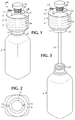
- the dispensing device 2 is designed to be connected to a fluid reservoir, for example a deformable resilient squeeze-type bottle 4.
- the squeeze-type bottle should be capable of being deformed by, for example, a human hand, in order to force fluid contained therein from the bottle and when released, the bottle should substantially return to its shape before squeezing.
- the dispensing device 2 includes a cup 8 having a top wall 10 and a bottom wall 12.
- the top wall 10 has a pourable orifice 14, preferably including a spout 15, from which the fluid in the cup 8 may be removed from the device 2.
- An air opening 16 is also present in the top wall 10 in order to permit the entry of air into the cup when pouring the fluid from the cup 8.
- the air opening 16 is positioned in the top wall, preferably diametrically opposed to the pourable orifice 14 so that the amount of fluid passing through the air opening 16 during the pouring process is minimized.
- the bottom wall 12 is connected to a fluid conduit 18, with a distal end 19, which extends into the deformable squeeze-type bottle 4 and permits fluid communication between the dispensing device 2 and the contents of the bottle 4.
- the bottom wall 12 also can include a coupling means 20 in order to securely position the dispensing device 2 on the deformable squeeze-type bottle 4.
- the coupling means can take the form of a threaded portion 22 which is cooperative with a complementary threaded portion 24 on the bottle 4.
- the top wall 10 also includes a central column 26 passing through an axial threaded opening 28.
- the central column 26 includes a threaded portion 30 which is cooperative with the axial threaded opening 28.
- the central column also includes a knob 32 and at least one orifice 34 preferably positioned at the base of the central column 26.
- Knob 32 permits adjustment of the vertical position of the orifice 34 by tuming the knob 32.
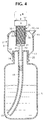
- the interaction of threaded portion 30 and axial threaded opening 28 permits for the vertical movement of the orifice 34 by the rotation of the knob 32, as shown in Fig. 4, for example, and movement from position A to position B, and vice versa.
- the top wall also includes, in the preferred embodiment, an arrow 36 or other symbol which is used to align an axial measurement scale 38 on the central column 26.
- the measurement scale 38 corresponds to the volumetric markings 56 on the cup 8.
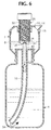
- the column orifice 34 is positioned at the proper vertical position in the cup 8 for the amount of fluid indicated on measurement scale 38 to be dispensed into cup 8 upon operation of the device as shown in Figs. 5 and 6.
- the measurement scale 38 on the column 26 can be in milliliters or fluid ounces.
- the central column 26 also includes a tubular portion 40 having a channel 41 which extends from the central column 26 and into the fluid conduit 18.
- the channel 41 of the tubular portion 40 is in fluid communication with the column orifice 34 as well as with the fluid conduit 18 to permit the flow of fluid from the bottle 4 into the cup 8.
- the tubular portion 40 is also movable relative to the fluid conduit 18 and annular thereto so as to be movable relative the fluid conduit. However, a substantial seal should be maintained between the tubular portion 40 and the fluid conduit 18 throughout the central column's vertical range of movement.
- the fluid conduit 18, in the preferred embodiment, should have a bend so that the distal end 19 of the tube opposes the pourable orifice 14. This minimizes the amount of fluid which could flow from the bottle 4, through the fluid conduit 18, and out the column orifice 34 upon the bottle 4 being tilted to pour the fluid out of the dispensing device. Further, the fluid conduit 18, even with the bend should be of a length so as to extend to the bottom of the bottle 4, so as to maximize the amount of fluid in the bottle 4 which can be deposited in the dispensing device and minimize waste.
- the radial position of the pourable orifice 14, air opening 16, and column orifice 34 is important. In order to minimize the amount of fluid which is lost out the pourable orifice 14 and the air opening 16 during the filling process, the pourable orifice 14 is radially positioned approximately 90 degrees from the column orifice 34.
- the deformable squeeze-type bottle 4 containing fluid and to which the dispensing device is mounted is squeezed by, for example, two fingers 42 in the direction of arrows 44 which forces the fluid up the fluid conduit 18 in the direction indicated by arrow 46.
- the fluid then proceeds up the fluid conduit 18, through the tubular portion 40 of central column 26, out the column orifice 34, and into the cup 8 of the dispensing device 2 as indicated by arrows 48.
- the dispensing device continues to fill with the fluid until the amount of volume displaced by squeezing the bottle is deposited in the bottle 4.
- the dispensing device includes volumetric markings 56 so as to provide the user with a direct way of visually confirming the amount of fluid dispensed in the device 2.
- the purpose for the two sets is to provide the user with greater accuracy in visually confirming the amount of fluid in the cup 8.
- between the two sets of markings it is possible to provide a gradient in increments of five milliliters.
- the alternatives which are less efficient, are to either use one set of markings in increments of ten milliliters which is less accurate or to use one set of markings in increments of five milliliters, where the lines are too close together and more difficult to read.
- the volume measurement scale 62 and the volumetric marking 64 cooperate to allow for a quick reading of the volume level.
- the preferred embodiment also includes a flange 66 on the rim of cup 8 which is cooperative with a slot 68 in the top wall 10.
- the flange 66 and corresponding slot 68 are positioned on their respective components in order to provide for consistent alignment of the top wall 10 relative to the remainder of the cup structure 8.
Landscapes
- Physics & Mathematics (AREA)
- Fluid Mechanics (AREA)
- General Physics & Mathematics (AREA)
- Closures For Containers (AREA)
- Devices For Dispensing Beverages (AREA)
- Sampling And Sample Adjustment (AREA)
- Containers And Packaging Bodies Having A Special Means To Remove Contents (AREA)
- Nozzles (AREA)
- Loading And Unloading Of Fuel Tanks Or Ships (AREA)
Applications Claiming Priority (2)
| Application Number | Priority Date | Filing Date | Title |
|---|---|---|---|
| US1799996P | 1996-05-21 | 1996-05-21 | |
| US17999 | 2001-12-14 |
Publications (2)
| Publication Number | Publication Date |
|---|---|
| EP0809091A1 true EP0809091A1 (de) | 1997-11-26 |
| EP0809091B1 EP0809091B1 (de) | 2006-09-20 |
Family
ID=21785722
Family Applications (1)
| Application Number | Title | Priority Date | Filing Date |
|---|---|---|---|
| EP97303316A Expired - Lifetime EP0809091B1 (de) | 1996-05-21 | 1997-05-15 | Flüssigkeitsabgabevorrichtung |
Country Status (8)
| Country | Link |
|---|---|
| US (1) | US5833124A (de) |
| EP (1) | EP0809091B1 (de) |
| AT (1) | ATE340354T1 (de) |
| AU (1) | AU708650B2 (de) |
| CA (1) | CA2205616C (de) |
| DE (1) | DE69736689D1 (de) |
| NZ (1) | NZ314857A (de) |
| ZA (1) | ZA974358B (de) |
Cited By (3)
| Publication number | Priority date | Publication date | Assignee | Title |
|---|---|---|---|---|
| WO1999060348A1 (en) * | 1998-04-27 | 1999-11-25 | Jan De Backer | Dose measuring apparatus for distributing a liquid |
| WO2001036921A1 (de) * | 1999-11-18 | 2001-05-25 | Alpla-Werke Alwin Lehner Gmbh & Co. Kg | Quetschflasche mit einer dosierkammer |
| WO2008064664A3 (de) * | 2006-11-30 | 2008-10-16 | Sigismund Laskowski | Dosiervorrichtung zum präzisen dosieren von verschiedenen portionen von flüssigem spendengut aus einem behältnis |
Families Citing this family (48)
| Publication number | Priority date | Publication date | Assignee | Title |
|---|---|---|---|---|
| US5992702A (en) * | 1997-01-22 | 1999-11-30 | Shapiro; Howard J. | Water bottle for pets and their owners |
| NL1009549C2 (nl) * | 1997-08-01 | 1999-02-02 | Sara Lee De Nv | Samenstel voorzien van een flexibele houder met een doseerinrichting en een doseerinrichting van een dergelijk samenstel. |
| USD416793S (en) * | 1998-11-02 | 1999-11-23 | Mcneil-Ppc, Inc. | Container, retaining member and dispensing instrument |
| USH2044H1 (en) | 1998-11-02 | 2002-09-03 | Mcneil-Ppc, Inc. | Container with retaining member |
| USD415961S (en) | 1998-11-02 | 1999-11-02 | Mcneil-Ppc, Inc. | Retaining member |
| USD416195S (en) | 1998-11-02 | 1999-11-09 | Mcneil-Ppc, Inc. | Container and retaining member |
| US6330960B1 (en) | 1999-06-04 | 2001-12-18 | Mcneil-Ppc, Inc. | Squeeze dispenser |
| US6435378B1 (en) * | 2001-05-25 | 2002-08-20 | Alexander Aptekman | Device for dispensing measured quantities of a fluid from a container and a metering container using such a device |
| US20040245290A1 (en) * | 2001-08-09 | 2004-12-09 | Tadashi Hagihara | Container with discharge flow velocity mechanism |
| US6877639B1 (en) * | 2002-10-18 | 2005-04-12 | Liquid measuring and dispensing device | |
| US20050067436A1 (en) * | 2003-09-26 | 2005-03-31 | Ching-Tien Pi | Bottle with constant liquid pouring device |
| US6923344B1 (en) * | 2004-01-14 | 2005-08-02 | Tops Equipment & Tools Co., Ltd. | Easy and quantitative liquid dispenser |
| US20060237485A1 (en) * | 2005-04-22 | 2006-10-26 | Iksoon An | All position spray bottle |
| US7731103B2 (en) * | 2005-09-19 | 2010-06-08 | Tropical Ventures Llc | Flowable product dispensing toy and methods of using the same |
| US8087968B2 (en) | 2005-05-23 | 2012-01-03 | Thought Development, Inc. | Device for discharging a stream of fluid in a pattern and method of using same |
| US20060261184A1 (en) * | 2005-05-23 | 2006-11-23 | Tropical Ventures, Llc | Device for discharging a stream of fluid in a pattern and method of using same |
| US7658213B1 (en) | 2005-09-29 | 2010-02-09 | Anderson Chemical Company | Fluid dispensing system |
| US7850043B2 (en) * | 2006-08-09 | 2010-12-14 | Replenish Bottling, Llc | Refillable/reusable mixer container and method of using same |
| US20100054636A1 (en) * | 2008-08-27 | 2010-03-04 | Cryovac, Inc. | Metering pouch for dispensing flowable product |
| US8434647B2 (en) * | 2009-08-08 | 2013-05-07 | Riad Aamar | Device for measuring and dispensing a prescribed amount of liquid |
| TWM375052U (en) * | 2009-10-07 | 2010-03-01 | zong-zhi Zhang | Liquid measuring cup structure which applicable to all kinds of bottles and cans |
| US8657158B1 (en) * | 2010-08-02 | 2014-02-25 | Jose L. Snell | Selectable flavor dispenser for a beverage container |
| CN102092592B (zh) * | 2010-12-08 | 2012-09-05 | 北京莱盛高新技术有限公司 | 多功能鼓粉盒再生墨粉填充装置 |
| US8974744B2 (en) * | 2011-06-08 | 2015-03-10 | Dan Llewllyn | Bottle for disinfecting toothbrush |
| USD747968S1 (en) | 2011-11-15 | 2016-01-26 | Husqvarna Ab | Bottle |
| USD682103S1 (en) | 2012-01-11 | 2013-05-14 | Dema Engineering Company | Bottle insert |
| US8870027B2 (en) | 2012-03-15 | 2014-10-28 | David G. Kraenzle | Multi-bottle containers for dispensing measured quantities of liquids |
| US9708093B2 (en) | 2012-08-20 | 2017-07-18 | Silgan Dispensing Systems Slatersville Llc | Dispensing closure for powdered products |
| US8579164B1 (en) * | 2012-09-13 | 2013-11-12 | Berlin Packaging, Llc | Dispensing bowl attachment for use with a bottle |
| EP2972134A4 (de) | 2013-03-15 | 2017-04-05 | Diversey, Inc. | Einstellbarer dosierverschluss |
| US9090396B2 (en) | 2013-04-17 | 2015-07-28 | Cryovac, Inc. | Pouch with metering handle for dispensing flowable products |
| GB2519206B (en) | 2013-08-17 | 2015-11-25 | Mwv Slatersville Llc | One-piece squeeze-to-dose dispensing closure |
| US20150090738A1 (en) * | 2013-09-27 | 2015-04-02 | Emsar S.P.A | Actuating device for a dispensing pump of a dispenser |
| US9120112B2 (en) * | 2013-10-16 | 2015-09-01 | Great Measures, Llc | Metered liquid dispensing bottle |
| USD746137S1 (en) | 2013-11-15 | 2015-12-29 | Diversey, Inc. | Dosing cap |
| USD723928S1 (en) | 2013-11-15 | 2015-03-10 | Diversey, Inc. | Container |
| US20170015474A1 (en) * | 2015-07-13 | 2017-01-19 | Plastek Industries, Inc. | Variable Metered Dose Closure |
| WO2018222698A1 (en) * | 2017-05-30 | 2018-12-06 | Ramadi Khalil | Method and apparatus for precise measurement and dispensing of liquids |
| EP3713849B1 (de) | 2017-11-24 | 2022-06-29 | Société des Produits Nestlé S.A. | Aufsatz für einen getränkebehälter |
| GB201720561D0 (en) * | 2017-12-10 | 2018-01-24 | Simard Jo-Anne | Fluid measuring and dispensing device |
| CN108639488A (zh) * | 2018-07-03 | 2018-10-12 | 丁要武 | 可调定量盖装置 |
| US10488242B1 (en) * | 2018-07-10 | 2019-11-26 | Silgan Dispensing Systems Corporation | Measured dose dispenser and methods of using the same |
| CN208924937U (zh) * | 2018-09-10 | 2019-06-04 | 乐烁榕城(深圳)实业有限公司 | 一种便携式宠物水壶 |
| US10499774B1 (en) * | 2018-11-13 | 2019-12-10 | John Ryan | Liquid dispenser |
| JP7227790B2 (ja) * | 2019-02-28 | 2023-02-22 | 株式会社吉野工業所 | 計量注出容器 |
| SE543832C2 (en) * | 2019-06-18 | 2021-08-03 | Bpc Instr Ab | Connectable fixation system intended as the space for performing chemical, biological or physical fixation |
| US12449293B2 (en) | 2020-09-30 | 2025-10-21 | Spectrum Brands, Inc. | Dosing bottle arrangement and methods |
| US11629986B2 (en) * | 2021-07-22 | 2023-04-18 | Curaleaf, Inc. | Squeeze doser with childproof cap |
Citations (7)
| Publication number | Priority date | Publication date | Assignee | Title |
|---|---|---|---|---|
| BE568579A (de) * | ||||
| GB777862A (en) * | 1954-11-09 | 1957-06-26 | H J Elliott Ltd | Improvements in or relating to a liquid dispenser |
| DE1075967B (de) * | 1956-05-07 | 1960-02-18 | Walter Schaedler | Elastische Dosierungs- und Transportflasche aus transparentem, elastischem Kunststoff |
| WO1989003362A1 (en) * | 1987-10-08 | 1989-04-20 | Chueng Tung Kong | Liquid dispensing apparatus |
| EP0335505A1 (de) * | 1988-03-30 | 1989-10-04 | Merck & Co. Inc. | Flüssigkeitsspender mit kontinuierlich einstellbarer Dosiervorrichtung |
| EP0552043A1 (de) * | 1992-01-15 | 1993-07-21 | Peter Kalabakas | Dosierer |
| US5363991A (en) * | 1986-02-07 | 1994-11-15 | Reyman Mark E | Device for the controlled measuring and dispensing of a fluid |
Family Cites Families (15)
| Publication number | Priority date | Publication date | Assignee | Title |
|---|---|---|---|---|
| US524206A (en) * | 1894-08-07 | Measuring-vessel | ||
| US1684171A (en) * | 1927-03-25 | 1928-09-11 | John H Davis | Liquid-dispensing device |
| US3246807A (en) * | 1963-05-13 | 1966-04-19 | Leeds & Micallef | Containers |
| GB1488355A (en) * | 1975-03-12 | 1977-10-12 | Wilkinson Photo Prod Ltd | Liquid dispensing device |
| US4105142A (en) * | 1976-10-07 | 1978-08-08 | Morris Jr Harold K | Dispensing device for fluid substances |
| GB2038779B (en) * | 1978-11-02 | 1982-11-03 | Bettix Ltd | Dispensing container |
| DE3241054A1 (de) * | 1982-11-06 | 1984-05-10 | Verpackungs-Industrie Kutenholz GmbH, 2741 Kutenholz | Vorrichtung zum dosierten ausgeben von fluessigkeiten aus zusammendrueckbaren behaeltern |
| GB8528138D0 (en) * | 1985-11-14 | 1985-12-18 | Plaspharm Uk Ltd | Dosage device |
| DE3618559A1 (de) * | 1986-06-03 | 1987-12-10 | Azza Sa | Vorrichtung zur entnahme von dosierten fluessigkeitsmengen |
| DE8708529U1 (de) * | 1987-06-19 | 1988-10-20 | Robert Finke KG, 5950 Finnentrop | Behälter zur dosierten Flüssigkeitsabgabe |
| FR2637366A1 (fr) * | 1988-10-05 | 1990-04-06 | Kerplas Snc | Dispositif doseur pour flacon a paroi deformable |
| US5381930A (en) * | 1992-01-15 | 1995-01-17 | Kalabakas; Peter | Dispensing device for a measured volume of liquid |
| DE9202091U1 (de) * | 1992-02-19 | 1992-05-07 | Buzil-Werk Julius Wagner, 8940 Memmingen | Dosiervorrichtung für deformierbare Flaschen |
| JP2829192B2 (ja) * | 1992-05-15 | 1998-11-25 | 住友電気工業株式会社 | レ−ザビ−ムスキャナ |
| US5649647A (en) * | 1995-08-10 | 1997-07-22 | Kodarar; Joseph | Transfer pump for chlorinated liquid |
-
1997
- 1997-05-07 US US08/852,554 patent/US5833124A/en not_active Expired - Fee Related
- 1997-05-15 EP EP97303316A patent/EP0809091B1/de not_active Expired - Lifetime
- 1997-05-15 DE DE69736689T patent/DE69736689D1/de not_active Expired - Lifetime
- 1997-05-15 AT AT97303316T patent/ATE340354T1/de not_active IP Right Cessation
- 1997-05-16 CA CA002205616A patent/CA2205616C/en not_active Expired - Fee Related
- 1997-05-20 AU AU23522/97A patent/AU708650B2/en not_active Ceased
- 1997-05-20 ZA ZA974358A patent/ZA974358B/xx unknown
- 1997-05-20 NZ NZ314857A patent/NZ314857A/en unknown
Patent Citations (7)
| Publication number | Priority date | Publication date | Assignee | Title |
|---|---|---|---|---|
| BE568579A (de) * | ||||
| GB777862A (en) * | 1954-11-09 | 1957-06-26 | H J Elliott Ltd | Improvements in or relating to a liquid dispenser |
| DE1075967B (de) * | 1956-05-07 | 1960-02-18 | Walter Schaedler | Elastische Dosierungs- und Transportflasche aus transparentem, elastischem Kunststoff |
| US5363991A (en) * | 1986-02-07 | 1994-11-15 | Reyman Mark E | Device for the controlled measuring and dispensing of a fluid |
| WO1989003362A1 (en) * | 1987-10-08 | 1989-04-20 | Chueng Tung Kong | Liquid dispensing apparatus |
| EP0335505A1 (de) * | 1988-03-30 | 1989-10-04 | Merck & Co. Inc. | Flüssigkeitsspender mit kontinuierlich einstellbarer Dosiervorrichtung |
| EP0552043A1 (de) * | 1992-01-15 | 1993-07-21 | Peter Kalabakas | Dosierer |
Cited By (4)
| Publication number | Priority date | Publication date | Assignee | Title |
|---|---|---|---|---|
| WO1999060348A1 (en) * | 1998-04-27 | 1999-11-25 | Jan De Backer | Dose measuring apparatus for distributing a liquid |
| US6334550B1 (en) | 1998-04-27 | 2002-01-01 | Jan De Backer | Dose measuring apparatus for distributing a liquid |
| WO2001036921A1 (de) * | 1999-11-18 | 2001-05-25 | Alpla-Werke Alwin Lehner Gmbh & Co. Kg | Quetschflasche mit einer dosierkammer |
| WO2008064664A3 (de) * | 2006-11-30 | 2008-10-16 | Sigismund Laskowski | Dosiervorrichtung zum präzisen dosieren von verschiedenen portionen von flüssigem spendengut aus einem behältnis |
Also Published As
| Publication number | Publication date |
|---|---|
| MX9703714A (es) | 1998-06-30 |
| EP0809091B1 (de) | 2006-09-20 |
| CA2205616A1 (en) | 1997-11-21 |
| AU708650B2 (en) | 1999-08-12 |
| US5833124A (en) | 1998-11-10 |
| ZA974358B (en) | 1998-11-20 |
| DE69736689D1 (de) | 2006-11-02 |
| NZ314857A (en) | 1998-05-27 |
| ATE340354T1 (de) | 2006-10-15 |
| AU2352297A (en) | 1997-11-27 |
| CA2205616C (en) | 2001-09-04 |
Similar Documents
| Publication | Publication Date | Title |
|---|---|---|
| EP0809091B1 (de) | Flüssigkeitsabgabevorrichtung | |
| CA1334660C (en) | Liquid dispensing apparatus | |
| AU604403B2 (en) | Fluid dispensing device with continuously variable dosage selection | |
| US5419465A (en) | Automatic volume dispensing fluid container | |
| US6082591A (en) | Graduated sight glass container | |
| CA1225619A (en) | Pouring spout | |
| US4828149A (en) | Tiltable metering dispenser | |
| US3805998A (en) | Dispensing pipette | |
| US5259536A (en) | Device for the controlled measuring and dispensing of a fluid | |
| ATE238822T1 (de) | Zähleinrichtung für eine flüssigkeitsabgabevorrichtung | |
| EP1844302A2 (de) | Flüssigkeitszufuhrvorrichtung mit messführung | |
| US5392966A (en) | Fluid dispensing device with gravity-fill continuously variable dosage selection | |
| US6334550B1 (en) | Dose measuring apparatus for distributing a liquid | |
| CA1323003C (en) | Fluid dispensing apparatus | |
| GB2224715A (en) | A device for measuring flow | |
| US5125541A (en) | Viscous liquid dispensing apparatus | |
| WO1990009568A1 (en) | Liquid dispensing apparatus | |
| EP0472363B1 (de) | Vorrichtung zur Bestimmung der Abweichung des Flüssigkeitsniveaus in einem Gefäss | |
| US20220289437A1 (en) | Liquid pouring spout | |
| MXPA97003714A (en) | Dispenser device of a flu | |
| US6244471B1 (en) | Metering container | |
| WO2006123327A2 (en) | Liquid dispenser for concurrent manual measuring and pouring and application thereof | |
| WO2001036920A1 (en) | A liquid dispensing apparatus | |
| SU1763002A1 (ru) | Пипетка | |
| SU1275222A1 (ru) | Устройство дл градуировки и контрол объема дозы дозаторов жидкости |
Legal Events
| Date | Code | Title | Description |
|---|---|---|---|
| PUAI | Public reference made under article 153(3) epc to a published international application that has entered the european phase |
Free format text: ORIGINAL CODE: 0009012 |
|
| 17P | Request for examination filed |
Effective date: 19970530 |
|
| AK | Designated contracting states |
Kind code of ref document: A1 Designated state(s): AT BE CH DE DK ES FI FR GB GR IE IT LI LU NL PT SE |
|
| GRAP | Despatch of communication of intention to grant a patent |
Free format text: ORIGINAL CODE: EPIDOSNIGR1 |
|
| GRAS | Grant fee paid |
Free format text: ORIGINAL CODE: EPIDOSNIGR3 |
|
| GRAA | (expected) grant |
Free format text: ORIGINAL CODE: 0009210 |
|
| AK | Designated contracting states |
Kind code of ref document: B1 Designated state(s): AT BE CH DE DK ES FI FR GB GR IE IT LI LU NL PT SE |
|
| PG25 | Lapsed in a contracting state [announced via postgrant information from national office to epo] |
Ref country code: NL Free format text: LAPSE BECAUSE OF FAILURE TO SUBMIT A TRANSLATION OF THE DESCRIPTION OR TO PAY THE FEE WITHIN THE PRESCRIBED TIME-LIMIT Effective date: 20060920 Ref country code: LI Free format text: LAPSE BECAUSE OF FAILURE TO SUBMIT A TRANSLATION OF THE DESCRIPTION OR TO PAY THE FEE WITHIN THE PRESCRIBED TIME-LIMIT Effective date: 20060920 Ref country code: IT Free format text: LAPSE BECAUSE OF FAILURE TO SUBMIT A TRANSLATION OF THE DESCRIPTION OR TO PAY THE FEE WITHIN THE PRESCRIBED TIME-LIMIT;WARNING: LAPSES OF ITALIAN PATENTS WITH EFFECTIVE DATE BEFORE 2007 MAY HAVE OCCURRED AT ANY TIME BEFORE 2007. THE CORRECT EFFECTIVE DATE MAY BE DIFFERENT FROM THE ONE RECORDED. Effective date: 20060920 Ref country code: FI Free format text: LAPSE BECAUSE OF FAILURE TO SUBMIT A TRANSLATION OF THE DESCRIPTION OR TO PAY THE FEE WITHIN THE PRESCRIBED TIME-LIMIT Effective date: 20060920 Ref country code: CH Free format text: LAPSE BECAUSE OF FAILURE TO SUBMIT A TRANSLATION OF THE DESCRIPTION OR TO PAY THE FEE WITHIN THE PRESCRIBED TIME-LIMIT Effective date: 20060920 Ref country code: BE Free format text: LAPSE BECAUSE OF FAILURE TO SUBMIT A TRANSLATION OF THE DESCRIPTION OR TO PAY THE FEE WITHIN THE PRESCRIBED TIME-LIMIT Effective date: 20060920 Ref country code: AT Free format text: LAPSE BECAUSE OF FAILURE TO SUBMIT A TRANSLATION OF THE DESCRIPTION OR TO PAY THE FEE WITHIN THE PRESCRIBED TIME-LIMIT Effective date: 20060920 |
|
| REG | Reference to a national code |
Ref country code: GB Ref legal event code: FG4D |
|
| REG | Reference to a national code |
Ref country code: CH Ref legal event code: EP |
|
| REG | Reference to a national code |
Ref country code: IE Ref legal event code: FG4D |
|
| REF | Corresponds to: |
Ref document number: 69736689 Country of ref document: DE Date of ref document: 20061102 Kind code of ref document: P |
|
| PG25 | Lapsed in a contracting state [announced via postgrant information from national office to epo] |
Ref country code: SE Free format text: LAPSE BECAUSE OF FAILURE TO SUBMIT A TRANSLATION OF THE DESCRIPTION OR TO PAY THE FEE WITHIN THE PRESCRIBED TIME-LIMIT Effective date: 20061220 Ref country code: DK Free format text: LAPSE BECAUSE OF FAILURE TO SUBMIT A TRANSLATION OF THE DESCRIPTION OR TO PAY THE FEE WITHIN THE PRESCRIBED TIME-LIMIT Effective date: 20061220 |
|
| PG25 | Lapsed in a contracting state [announced via postgrant information from national office to epo] |
Ref country code: DE Free format text: LAPSE BECAUSE OF FAILURE TO SUBMIT A TRANSLATION OF THE DESCRIPTION OR TO PAY THE FEE WITHIN THE PRESCRIBED TIME-LIMIT Effective date: 20061221 |
|
| PG25 | Lapsed in a contracting state [announced via postgrant information from national office to epo] |
Ref country code: ES Free format text: LAPSE BECAUSE OF FAILURE TO SUBMIT A TRANSLATION OF THE DESCRIPTION OR TO PAY THE FEE WITHIN THE PRESCRIBED TIME-LIMIT Effective date: 20061231 |
|
| NLV1 | Nl: lapsed or annulled due to failure to fulfill the requirements of art. 29p and 29m of the patents act | ||
| PG25 | Lapsed in a contracting state [announced via postgrant information from national office to epo] |
Ref country code: PT Free format text: LAPSE BECAUSE OF FAILURE TO SUBMIT A TRANSLATION OF THE DESCRIPTION OR TO PAY THE FEE WITHIN THE PRESCRIBED TIME-LIMIT Effective date: 20070312 |
|
| REG | Reference to a national code |
Ref country code: CH Ref legal event code: PL |
|
| EN | Fr: translation not filed | ||
| PLBE | No opposition filed within time limit |
Free format text: ORIGINAL CODE: 0009261 |
|
| STAA | Information on the status of an ep patent application or granted ep patent |
Free format text: STATUS: NO OPPOSITION FILED WITHIN TIME LIMIT |
|
| 26N | No opposition filed |
Effective date: 20070621 |
|
| GBPC | Gb: european patent ceased through non-payment of renewal fee |
Effective date: 20070515 |
|
| PG25 | Lapsed in a contracting state [announced via postgrant information from national office to epo] |
Ref country code: GR Free format text: LAPSE BECAUSE OF FAILURE TO SUBMIT A TRANSLATION OF THE DESCRIPTION OR TO PAY THE FEE WITHIN THE PRESCRIBED TIME-LIMIT Effective date: 20061221 Ref country code: FR Free format text: LAPSE BECAUSE OF FAILURE TO SUBMIT A TRANSLATION OF THE DESCRIPTION OR TO PAY THE FEE WITHIN THE PRESCRIBED TIME-LIMIT Effective date: 20070518 |
|
| PG25 | Lapsed in a contracting state [announced via postgrant information from national office to epo] |
Ref country code: IE Free format text: LAPSE BECAUSE OF NON-PAYMENT OF DUE FEES Effective date: 20070515 Ref country code: GB Free format text: LAPSE BECAUSE OF NON-PAYMENT OF DUE FEES Effective date: 20070515 |
|
| PG25 | Lapsed in a contracting state [announced via postgrant information from national office to epo] |
Ref country code: FR Free format text: LAPSE BECAUSE OF FAILURE TO SUBMIT A TRANSLATION OF THE DESCRIPTION OR TO PAY THE FEE WITHIN THE PRESCRIBED TIME-LIMIT Effective date: 20060920 |
|
| PG25 | Lapsed in a contracting state [announced via postgrant information from national office to epo] |
Ref country code: LU Free format text: LAPSE BECAUSE OF NON-PAYMENT OF DUE FEES Effective date: 20070515 |