EP0809164A1 - Steuerungssystem zum Steuern mehrerer Vakuumpumpen - Google Patents
Steuerungssystem zum Steuern mehrerer Vakuumpumpen Download PDFInfo
- Publication number
- EP0809164A1 EP0809164A1 EP97108201A EP97108201A EP0809164A1 EP 0809164 A1 EP0809164 A1 EP 0809164A1 EP 97108201 A EP97108201 A EP 97108201A EP 97108201 A EP97108201 A EP 97108201A EP 0809164 A1 EP0809164 A1 EP 0809164A1
- Authority
- EP
- European Patent Office
- Prior art keywords
- vacuum
- vacuum pump
- pump
- control system
- controller
- Prior art date
- Legal status (The legal status is an assumption and is not a legal conclusion. Google has not performed a legal analysis and makes no representation as to the accuracy of the status listed.)
- Granted
Links
Images





Classifications
-
- F—MECHANICAL ENGINEERING; LIGHTING; HEATING; WEAPONS; BLASTING
- F04—POSITIVE - DISPLACEMENT MACHINES FOR LIQUIDS; PUMPS FOR LIQUIDS OR ELASTIC FLUIDS
- F04B—POSITIVE-DISPLACEMENT MACHINES FOR LIQUIDS; PUMPS
- F04B49/00—Control, e.g. of pump delivery, or pump pressure of, or safety measures for, machines, pumps, or pumping installations, not otherwise provided for, or of interest apart from, groups F04B1/00 - F04B47/00
- F04B49/007—Installations or systems with two or more pumps or pump cylinders, wherein the flow-path through the stages can be changed, e.g. from series to parallel
-
- G—PHYSICS
- G05—CONTROLLING; REGULATING
- G05B—CONTROL OR REGULATING SYSTEMS IN GENERAL; FUNCTIONAL ELEMENTS OF SUCH SYSTEMS; MONITORING OR TESTING ARRANGEMENTS FOR SUCH SYSTEMS OR ELEMENTS
- G05B19/00—Program-control systems
- G05B19/02—Program-control systems electric
- G05B19/418—Total factory control, i.e. centrally controlling a plurality of machines, e.g. direct or distributed numerical control [DNC], flexible manufacturing systems [FMS], integrated manufacturing systems [IMS] or computer integrated manufacturing [CIM]
- G05B19/4185—Total factory control, i.e. centrally controlling a plurality of machines, e.g. direct or distributed numerical control [DNC], flexible manufacturing systems [FMS], integrated manufacturing systems [IMS] or computer integrated manufacturing [CIM] characterised by the network communication
-
- F—MECHANICAL ENGINEERING; LIGHTING; HEATING; WEAPONS; BLASTING
- F04—POSITIVE - DISPLACEMENT MACHINES FOR LIQUIDS; PUMPS FOR LIQUIDS OR ELASTIC FLUIDS
- F04B—POSITIVE-DISPLACEMENT MACHINES FOR LIQUIDS; PUMPS
- F04B37/00—Pumps having pertinent characteristics not provided for in, or of interest apart from, groups F04B25/00 - F04B35/00
- F04B37/06—Pumps having pertinent characteristics not provided for in, or of interest apart from, groups F04B25/00 - F04B35/00 for evacuating by thermal means
- F04B37/08—Pumps having pertinent characteristics not provided for in, or of interest apart from, groups F04B25/00 - F04B35/00 for evacuating by thermal means by condensing or freezing, e.g. cryogenic pumps
-
- F—MECHANICAL ENGINEERING; LIGHTING; HEATING; WEAPONS; BLASTING
- F04—POSITIVE - DISPLACEMENT MACHINES FOR LIQUIDS; PUMPS FOR LIQUIDS OR ELASTIC FLUIDS
- F04B—POSITIVE-DISPLACEMENT MACHINES FOR LIQUIDS; PUMPS
- F04B37/00—Pumps having pertinent characteristics not provided for in, or of interest apart from, groups F04B25/00 - F04B35/00
- F04B37/10—Pumps having pertinent characteristics not provided for in, or of interest apart from, groups F04B25/00 - F04B35/00 for special use
- F04B37/14—Pumps having pertinent characteristics not provided for in, or of interest apart from, groups F04B25/00 - F04B35/00 for special use to obtain high vacuum
-
- F—MECHANICAL ENGINEERING; LIGHTING; HEATING; WEAPONS; BLASTING
- F04—POSITIVE - DISPLACEMENT MACHINES FOR LIQUIDS; PUMPS FOR LIQUIDS OR ELASTIC FLUIDS
- F04B—POSITIVE-DISPLACEMENT MACHINES FOR LIQUIDS; PUMPS
- F04B49/00—Control, e.g. of pump delivery, or pump pressure of, or safety measures for, machines, pumps, or pumping installations, not otherwise provided for, or of interest apart from, groups F04B1/00 - F04B47/00
- F04B49/06—Control using electricity
- F04B49/065—Control using electricity and making use of computers
-
- F—MECHANICAL ENGINEERING; LIGHTING; HEATING; WEAPONS; BLASTING
- F04—POSITIVE - DISPLACEMENT MACHINES FOR LIQUIDS; PUMPS FOR LIQUIDS OR ELASTIC FLUIDS
- F04D—NON-POSITIVE-DISPLACEMENT PUMPS
- F04D19/00—Axial-flow pumps
- F04D19/02—Multi-stage pumps
- F04D19/04—Multi-stage pumps specially adapted to the production of a high vacuum, e.g. molecular pumps
-
- F—MECHANICAL ENGINEERING; LIGHTING; HEATING; WEAPONS; BLASTING
- F04—POSITIVE - DISPLACEMENT MACHINES FOR LIQUIDS; PUMPS FOR LIQUIDS OR ELASTIC FLUIDS
- F04D—NON-POSITIVE-DISPLACEMENT PUMPS
- F04D25/00—Pumping installations or systems
- F04D25/16—Combinations of two or more pumps ; Producing two or more separate gas flows
-
- F—MECHANICAL ENGINEERING; LIGHTING; HEATING; WEAPONS; BLASTING
- F04—POSITIVE - DISPLACEMENT MACHINES FOR LIQUIDS; PUMPS FOR LIQUIDS OR ELASTIC FLUIDS
- F04D—NON-POSITIVE-DISPLACEMENT PUMPS
- F04D27/00—Control, e.g. regulation, of pumps, pumping installations or pumping systems specially adapted for elastic fluids
-
- F—MECHANICAL ENGINEERING; LIGHTING; HEATING; WEAPONS; BLASTING
- F25—REFRIGERATION OR COOLING; COMBINED HEATING AND REFRIGERATION SYSTEMS; HEAT PUMP SYSTEMS; MANUFACTURE OR STORAGE OF ICE; LIQUEFACTION SOLIDIFICATION OF GASES
- F25B—REFRIGERATION MACHINES, PLANTS OR SYSTEMS; COMBINED HEATING AND REFRIGERATION SYSTEMS; HEAT PUMP SYSTEMS
- F25B2400/00—Component parts or details not otherwise provided for in this subclass
- F25B2400/06—Several compression cycles arranged in parallel
-
- G—PHYSICS
- G05—CONTROLLING; REGULATING
- G05B—CONTROL OR REGULATING SYSTEMS IN GENERAL; FUNCTIONAL ELEMENTS OF SUCH SYSTEMS; MONITORING OR TESTING ARRANGEMENTS FOR SUCH SYSTEMS OR ELEMENTS
- G05B2219/00—Program-control systems
- G05B2219/30—Nc systems
- G05B2219/31—From computer integrated manufacturing till monitoring
- G05B2219/31102—Program network controller, connected devices
-
- G—PHYSICS
- G05—CONTROLLING; REGULATING
- G05B—CONTROL OR REGULATING SYSTEMS IN GENERAL; FUNCTIONAL ELEMENTS OF SUCH SYSTEMS; MONITORING OR TESTING ARRANGEMENTS FOR SUCH SYSTEMS OR ELEMENTS
- G05B2219/00—Program-control systems
- G05B2219/30—Nc systems
- G05B2219/31—From computer integrated manufacturing till monitoring
- G05B2219/31103—Configure parameters of controlled devices
-
- G—PHYSICS
- G05—CONTROLLING; REGULATING
- G05B—CONTROL OR REGULATING SYSTEMS IN GENERAL; FUNCTIONAL ELEMENTS OF SUCH SYSTEMS; MONITORING OR TESTING ARRANGEMENTS FOR SUCH SYSTEMS OR ELEMENTS
- G05B2219/00—Program-control systems
- G05B2219/30—Nc systems
- G05B2219/31—From computer integrated manufacturing till monitoring
- G05B2219/31104—Remote configuration of parameters of controlled devices
-
- G—PHYSICS
- G05—CONTROLLING; REGULATING
- G05B—CONTROL OR REGULATING SYSTEMS IN GENERAL; FUNCTIONAL ELEMENTS OF SUCH SYSTEMS; MONITORING OR TESTING ARRANGEMENTS FOR SUCH SYSTEMS OR ELEMENTS
- G05B2219/00—Program-control systems
- G05B2219/30—Nc systems
- G05B2219/31—From computer integrated manufacturing till monitoring
- G05B2219/31105—Remote control of network controller
-
- G—PHYSICS
- G05—CONTROLLING; REGULATING
- G05B—CONTROL OR REGULATING SYSTEMS IN GENERAL; FUNCTIONAL ELEMENTS OF SUCH SYSTEMS; MONITORING OR TESTING ARRANGEMENTS FOR SUCH SYSTEMS OR ELEMENTS
- G05B2219/00—Program-control systems
- G05B2219/30—Nc systems
- G05B2219/31—From computer integrated manufacturing till monitoring
- G05B2219/31115—Network controller
-
- G—PHYSICS
- G05—CONTROLLING; REGULATING
- G05B—CONTROL OR REGULATING SYSTEMS IN GENERAL; FUNCTIONAL ELEMENTS OF SUCH SYSTEMS; MONITORING OR TESTING ARRANGEMENTS FOR SUCH SYSTEMS OR ELEMENTS
- G05B2219/00—Program-control systems
- G05B2219/30—Nc systems
- G05B2219/31—From computer integrated manufacturing till monitoring
- G05B2219/31123—Multi mode network controller, monitor, control, configuration, maintenance
-
- G—PHYSICS
- G05—CONTROLLING; REGULATING
- G05B—CONTROL OR REGULATING SYSTEMS IN GENERAL; FUNCTIONAL ELEMENTS OF SUCH SYSTEMS; MONITORING OR TESTING ARRANGEMENTS FOR SUCH SYSTEMS OR ELEMENTS
- G05B2219/00—Program-control systems
- G05B2219/30—Nc systems
- G05B2219/31—From computer integrated manufacturing till monitoring
- G05B2219/31206—Exchange of parameters, data, programs between two station, station and central or host or remote
-
- G—PHYSICS
- G05—CONTROLLING; REGULATING
- G05B—CONTROL OR REGULATING SYSTEMS IN GENERAL; FUNCTIONAL ELEMENTS OF SUCH SYSTEMS; MONITORING OR TESTING ARRANGEMENTS FOR SUCH SYSTEMS OR ELEMENTS
- G05B2219/00—Program-control systems
- G05B2219/30—Nc systems
- G05B2219/31—From computer integrated manufacturing till monitoring
- G05B2219/31237—Host and rs232, rs485 to network controller and rs232 to controlled devices
-
- G—PHYSICS
- G05—CONTROLLING; REGULATING
- G05B—CONTROL OR REGULATING SYSTEMS IN GENERAL; FUNCTIONAL ELEMENTS OF SUCH SYSTEMS; MONITORING OR TESTING ARRANGEMENTS FOR SUCH SYSTEMS OR ELEMENTS
- G05B2219/00—Program-control systems
- G05B2219/30—Nc systems
- G05B2219/37—Measurements
- G05B2219/37252—Life of tool, service life, decay, wear estimation
-
- Y—GENERAL TAGGING OF NEW TECHNOLOGICAL DEVELOPMENTS; GENERAL TAGGING OF CROSS-SECTIONAL TECHNOLOGIES SPANNING OVER SEVERAL SECTIONS OF THE IPC; TECHNICAL SUBJECTS COVERED BY FORMER USPC CROSS-REFERENCE ART COLLECTIONS [XRACs] AND DIGESTS
- Y02—TECHNOLOGIES OR APPLICATIONS FOR MITIGATION OR ADAPTATION AGAINST CLIMATE CHANGE
- Y02P—CLIMATE CHANGE MITIGATION TECHNOLOGIES IN THE PRODUCTION OR PROCESSING OF GOODS
- Y02P90/00—Enabling technologies with a potential contribution to greenhouse gas [GHG] emissions mitigation
- Y02P90/02—Total factory control, e.g. smart factories, flexible manufacturing systems [FMS] or integrated manufacturing systems [IMS]
Definitions
- the present invention relates to a vacuum pump control system, and more particularly to a vacuum pump control system which can control a plurality of vacuum pumps comprising at least one type of cryopump, turbomolecular pump, cryoturbo pump, and dry pump such as a Roots type vacuum pump.
- Cryopumps have a first-stage cryopanel cooled to a temperature of 60K - 80K for condensing water or the like, a second-stage cryopanel cooled to a temperature of 10K - 20K for condensing a nitrogen gas (N 2 ), an argon gas (Ar) or the like, and an activated charcoal layer mounted on the second-stage cryopanel for adsorbing at a low temperature a hydrogen gas (H 2 ) or the like that is not condensed at a temperature of 10K - 20K.
- the cryopump is generally used to develop a high vacuum in a vacuum chamber of a semiconductor fabrication facility such as a sputtering apparatus or an ion implantation apparatus.
- cryopump is a storage type vacuum pump, and hence need to be regenerated, i.e., to release the condensed or adsorbed gases from a cryopanel at periodic intervals. It is therefore necessary to control the cryopumps for regeneration.
- Turbomolecular pumps dry pumps comprising a Roots type vacuum pump, cryoturbo pumps, etc. are also used to develop a high vacuum in a vacuum chamber although they operate by different principles.
- Recent semiconductor fabrication facilities have a plurality of vacuum chambers which are associated with respective vacuum pumps that may be of different types depending on processing conditions in the vacuum chambers. It is therefore necessary for the control system of the semiconductor fabrication facility to monitor and control the vacuum pumps of different kinds.
- the vacuum pumps are controlled by respective controllers which are connected to the control system of the semiconductor fabrication facility.
- One system for controlling a plurality of vacuum pumps employs a daisy chain communications network which is a type of computer network.
- a network control unit connected to a host computer is connected to a series-connected array of vacuum pump controllers which control respective vacuum pumps.
- This system is advantageous in that when the network control unit is apart from the vacuum pump controllers, or the vacuum pump controllers are apart from one another, the number of long cables can be reduced to a minimum.
- the daisy chain communications network suffers a problem in that since command signals from the host computer and/or the network control unit cannot be delivered simultaneously to all the vacuum pump controllers, a considerable time is required for communication between the controllers and control of all the vacuum pumps.
- Another object of the present invention is to provide a vacuum pump control system which has a multi-controller capable of controlling a plurality of vacuum pumps, and controlling a plurality of types of vacuum pumps.
- a vacuum pump control system for controlling a plurality of vacuum pumps, comprising: a host computer; a plurality of vacuum pump controllers connected respectively to the vacuum pumps; and a network control unit for transmitting information between the host computer and the vacuum pump controllers, the vacuum pump controllers being connected in parallel to the network control unit by respective communication lines.
- the network control unit can simultaneously control the vacuum pump controllers. Therefore, command signals from the network control unit can immediately reach the vacuum pump controllers at the same time for quickly controlling the vacuum pumps.
- a vacuum pump control system for controlling a plurality of vacuum pumps, comprising: a host computer; and a multi-controller connected between the host computer and the vacuum pumps for controlling the vacuum pumps.
- a plurality of vacuum pumps can be monitored and controlled by the single multi-controller.
- Control modules are detachably inserted in the multi-controller for controlling the vacuum pumps.
- the vacuum pumps which need to be monitored and controlled can thus be handled by a minimum amount of hardware provided by the control modules.
- Different types of vacuum pumps and a plurality of vacuum pumps can be monitored and controlled by installing control modules corresponding to types of vacuum pumps in the multi-controller.
- the host computer which may serve as a controller of a semiconductor fabrication facility using the vacuum pumps, can therefore monitor and control different types of vacuum pumps and a plurality of vacuum pumps by exchanging information with the multi-controller.
- FIGS. 1 through 4 A vacuum pump control system according to a first embodiment of a first aspect of the present invention will be described below with reference to FIGS. 1 through 4.
- a plurality of cryopumps 10 are connected respectively to vacuum chambers 1 of a semiconductor fabrication facility such as a sputtering apparatus or an etching apparatus.
- the cryopumps 10 are also connected to respective vacuum pump controllers 2 which control the corresponding cryopumps 10 to operate in various modes, e.g., start the cryopumps 10, stop the cryopumps 10, and start a regenerating process of the cryopumps 10.
- a dry pump comprising a Roots type vacuum pump (not shown) is provided at the downstream of the cryopump for assisting evacuation of the cryopump.
- the vacuum pump controllers 2 are connected in parallel to a network control unit 3 by respective RS-232C cables, and the network control unit 3 is connected to a host computer 4 of the semiconductor fabrication facility by an RS-232C cable.
- the network control unit 3 has a relay function to deliver command signals, e.g., command signals for starting the cryopumps 10, stopping the cryopumps 10, and starting the regenerating process from the host computer 4, to the vacuum pump controllers 2, and also to transmit signals from the vacuum pump controllers 2 to the host computer 4.
- the network control unit 3 also has a control function to set and modify control variables for the cryopumps 10, and a display function to display operation statuses of the cryopumps 10 and values of temperature, pressure, etc. in the cryopumps 10.
- the operation statuses include operating status, stopping status, regenerating status and the like.
- the network control unit 3 further has a maintenance function to integrate the operation times of the cryopumps 10 and determine the timing of regeneration of the cryopumps 10 and the timing of maintenance on the cryopumps 10, and a manual control function to allow the cryopumps 10 and valves and other devices thereof to be manually operated.
- a remote controller 5 for setting and modifying control variables for the cryopumps 10.
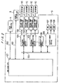
- FIG. 2 shows a one-board block scheme (enclosed by the dot-and-dash line) of the network control unit 3 and its relation to the other devices of the vacuum pump control system.
- the network control unit 3 has various devices on one board for simultaneously controlling the vacuum pump controllers 2, and is connected to the host computer 4 and the remote controller 5 by communication lines 102.
- the network control unit 3 has a one-chip CPU 101 connected by a bus 103 to a plurality of external communication devices 104, a nonvolatile memory 105, and an output/input device 106.
- Each of the external communication devices 104 has two communication lines 102 and can be connected to two vacuum pump controllers 2. Therefore, the number of external communication devices 104 in the network control unit 3 is determined depending on the number of cryopumps 10 to be controlled by the vacuum pump control system.
- Switches 107, light-emitting diodes 108, and liquid-crystal display units 109 are connected to the output/input device 106.
- the network control unit 3 is supplied with electric power through a power supply cable (not shown).
- a power switch of the switches 107 When a power switch of the switches 107 is turned on, the one-chip CPU 101 reads settings such as control variables from the nonvolatile memory 105 for performing the functions of the network control unit 3.
- Command signals delivered from the host computer 4 or the remote controller 5 through the communication lines 102 are processed by the one-chip CPU 101, and transmitted through transmission paths including the bus 103, the external communication devices 104, and the communication lines 102 to the vacuum pump controllers 2. Even if a plurality of command signals are simultaneously supplied, they can be transmitted in parallel to the vacuum pump controllers 2 through the communication lines 102.
- Signals from the vacuum pump controllers 2 are transmitted to the host computer 4 through transmission paths which are a reversal of the above transmission paths.
- signals are entered from the switches 107 serving as a keyboard and supplied through the output/input device 106 and the bus 103 to the one-chip CPU 101.
- the signals are then processed by the one-chip CPU 101, and delivered through the bus 103 and the external communication device 104 to the vacuum pump controllers 2.
- An input for setting and modifying control variables may be made from the host computer 4 or the remote controller 5.
- Data indicative of operation statuses of the cryopumps 10 and values of temperature, pressure, etc. in the cryopumps 10 are supplied from the cryopumps 10 through the vacuum pump controllers 2, the communication lines 102, the external communication devices 104, the bus 103, the one-chip CPU 101, the bus 103, and the output/input device 106 to the liquid-crystal display unit 109 and the light-emitting diodes 108, and the liquid-crystal display unit 109 and the light-emitting diodes 108 display the operation statuses and the values.
- the operation statuses and the values can also be displayed on the remote controller 5.
- the one-chip CPU 101 has a built-in timer for calculating or integrating the operation times of the cryopumps 10. According to the maintenance function, the one-chip CPU 101 determines the timing to regenerate the cryopumps 10 and the timing to perform maintenance on the cryopumps 10 based on the calculated operation times, and displays the determined timings on the liquid-crystal display unit 109 and the remote controller 5.
- the network control unit 3 allows the cryopumps 10 and valves and other devices thereof to be manually operated, i.e., started, stopped, started for regeneration, and opened and closed, in response to signals entered through the switches 107.
- the remote controller 5 has all the functions which the network control unit 3 has, except for the relay function to deliver command signals from the host computer 4 to the vacuum pump controllers 2 and to transmit signals from the vacuum pump controllers 2 to the host computer 4. Therefore, the remote controller 5 may be located in any place where the operator is immediately accessible and can quickly manipulate the remote controller 5, for controlling the network control unit 3. With the remote controller 5, the operator finds it highly convenient to control the cryopumps 10.
- the communication lines 102 and peripheral devices connected thereto will be described below with reference to FIG. 3.
- the network control unit 3 is shown on a left-hand side, and the host computer 4 or the vacuum pump controller 2 is shown on a right-hand side.
- the network control unit 3 has the one-chip CPU 101 therein which is connected to the external communication device 104 through the bus 103.
- the external communication device 104 comprising an RS-232C driver, communicates with the vacuum pump controller 2 or the host computer 4 through a connector 110 and the communication lines 102.
- the host computer 4 or the vacuum pump controller 2 also has a CPU 116, an external communication device 114 comprising an RS-232C driver, and a connector 112 which is connected to the communication lines 102, each comprising an RS-232C cable.
- each of the communication lines 102 preferably comprises an RS-232C cable. It is not necessary for each of the cryopumps 10 to be associated with and controlled by a vacuum pump controller 2. For space-saving considerations, it is also preferable to use one vacuum pump controller 2 to control a plurality of cryopumps.
- FIG. 4 shows in front elevation the front panel of the network control unit 3.
- the front panel has the liquid-crystal display panel 109, a power switch 200, the light-emitting diodes 108, and the switches 107.
- the switches 107 include a mode select switch, a pump select switch, an enter switch, and arrow switches.
- the mode select switch is used to select a monitor mode, a control mode, a regeneration mode, a configuration mode, and a maintenance mode. For selecting the monitor mode, the mode select switch is pressed, and one of the light-emitting diodes 108 which is labeled as "Monitor" is turned on. The monitor mode is selected as an initial setting.
- the liquid-crystal display panel 109 displays the values of temperature and pressure in a selected cryopump, whether the selected cryopump is operating or stopped or being regenerated. If a different cryopump is to be monitored, the pump select key 107 is pressed and the arrow keys 107 are pressed until the desired cryopump is selected. For selecting the control mode, the mode select switch is pressed again, and one of the light-emitting diodes 108 which is labeled as "Control" is turned on. In the control mode, a selected cryopump can manually be turned on and off by the enter switch 107.
- a selected cryopump can manually be turned on and off by the enter switch 107.
- control parameters and regeneration parameters for a selected cryopump can be set. Numerical values of those control parameters and regeneration parameters can be varied by the arrow switches 107, and entered by the enter switch 107.
- a purge valve and a roughing valve which are attached to a selected cryopump can be manually opened and closed, and an operation time of the cryopump and a time from the regeneration mode can be set and displayed.
- the vacuum pump controllers 2 are connected in parallel to the network control unit 3 by as many communication lines as the number of the vacuum pump controllers 2, to allow the network control unit 3 to simultaneously control the vacuum pump controllers 2. Therefore, command signals from the network control unit 3 can immediately reach the vacuum pump controllers 2 at the same time for quickly controlling the vacuum pumps.
- RS-232C cables are used as the communication lines. Therefore, if the host computer 4 and the vacuum pump controllers 2 are apart from each other by a distance of 30 m or more, then no communications may possibly be carried out between the host computer 4 and the vacuum pump controllers 2 through the communication lines. Furthermore, if the network control unit 3 and the vacuum pump controllers 2 are apart from each other by a large distance, a plurality of communication lines extend therebetween over the large distance and occupy a large space and present an unsightly appearance.
- FIG. 5 A vacuum pump control system according to a second embodiment of the first aspect of the present invention will be described below with reference to FIG. 5.
- the system shown in FIG. 5 is designed to eliminate the above drawback.
- the external communication devices 104 which are contained in one board of the network control unit 3 according to the above embodiment shown in FIG. 2, are placed on another board, i.e., housed in a distributor 300.
- the network control unit 3 and the distributor 300 are interconnected by an RS-485 cable, for example.
- the distributor 300 are connected to the vacuum pump controllers 2 by RS-232C cables.
- the RS-485 cable allows communications to be effected between the host computer 4 and the vacuum pump controllers 2 even when they are apart from each other by a distance of 30 m or more.
- the vacuum pump control system shown in FIG. 5 also offers the same advantages as the vacuum pump control system shown in FIG. 1.
- cryopumps 10 and peripheral devices connected thereto will be described below with reference to FIG. 6.
- the cryopump 10 has a refrigerator 71 to which a compressor unit 20 is connected through pipes 21.
- the refrigerator 71 has an expander 72 which is vertically movable by an expander motor 30.
- a working gas helium (He) gas
- He helium
- the expander 72 has first- and second-stage seals 72-1, 72-2.
- a first-stage cryopanel 16 is mounted on an upper end of the first-stage expanding portion 73 by a thermally conductive element 15.
- a second-stage cryopanel 17 is mounted directly on the second-stage expanding portion 74.
- the first-stage expanding portion 73 and the second-stage expanding portion 74 of the refrigerator 71 are surrounded by a casing 18.
- the vacuum chamber 1 shown in FIG. 1 is connected to an upper end of the casing 18.
- the cryopump 10 operates as follows: A high-pressure working gas from the compressor unit 20 is supplied to the refrigerator 71 through a valve (not shown) which is opened and closed in response to vertical movement of the expander 72, and adiabatically expanded in the first-stage expanding portion 73 and the second-stage expanding portion 74 which are cooled to a cryogenic temperature.
- the expanded working gas is delivered through a fluid passage (not shown) to the expander motor 30. After cooling the expander motor 30, the working gas is sent to the compressor unit 20.
- the working gas is compressed by the compressor unit 20 and processed to separate oil therefrom.
- the working gas is supplied again under a high pressure to the refrigerator 71.
- the first-stage expanding portion 73 and the second-stage expanding portion 74 which are cooled to the cryogenic temperature cool the first-stage cryopanel 16 and the second-stage cryopanel 17, respectively.
- the first-stage cryopanel 16 and the second-stage cryopanel 17 When the first-stage cryopanel 16 and the second-stage cryopanel 17 are cooled, the first-stage cryopanel 16 condenses on its surface mainly moisture in the vacuum chamber 1, and the second-stage cryopanel 17 condenses on its surface mainly an argon gas (Ar) and a nitrogen gas (N 2 ). Further, a hydrogen gas (H 2 ) is absorbed at the low temperature by an activated charcoal layer on the reverse side of the second-stage cryopanel 17. In this manner, the gases in the vacuum chamber 1 are evacuated.
- Ar argon gas
- N 2 nitrogen gas
- a temperature sensor 32 for detecting the surface temperature of the first-stage cryopanel 16 is attached to the first-stage cryopanel 16.
- a detected output signal from the temperature sensor 32 is supplied to a control device 2A of the vacuum pump controller 2.
- the control device 2A outputs a command signal for controlling the rotational speed of the expander motor 30 to an expander motor drive device 2B.
- the expander motor drive device 2B controls the rotational speed of the expander motor 30.
- the vacuum pump controller 2 thus keeps the surface temperature of the first-stage cryopanel 16 at the predetermined level for thereby stably evacuating the gases from the vacuum chamber 1.
- the vacuum pump controller 2 also has a regeneration control function. In the regeneration mode, after confirming that a valve (not shown) between the vacuum chamber 1 and the cryopump 10 is closed, the vacuum pump controller 2 stops the cryopump 10, turns on a purge heater 36, opens a purge valve 38 connected to the cryopump 10, thereby increasing the temperature and pressure in the cryopump 10. The vacuum pump controller 2 also turns on heaters 44, 46 attached respectively to the first-stage expanding portion 73 and the second-stage expanding portion 74 to heat the interior of the cryopump 10. When the pressure in the cryopump 10 reaches an atmospheric pressure, a relief valve 41 connected to the cryopump 10 is automatically opened to discharge the gases from the cryopump 10.
- the vacuum pump controller 2 turns off the heaters 44, 46.
- the vacuum pump controller 2 closes the purge valve 38 and opens a roughing valve 40 connected to the cryopump 10, and actuates a roughing pump (not shown) connected downstream of the vacuum pump controller 2 to lower the pressure in the cryopump 10.
- the vacuum pump controller 2 closes the roughing valve 40 in order to check whether the cryopump 10 has completely been regenerated or not. If the cryopump 10 has insufficiently been regenerated, then since the pressure in the cryopump 10 increases to a level higher than a predetermined level, the cryopump 10 is roughly evacuated or regenerated again. The pressure in the cryopump 10 is measured by a vacuum gage 42.
- the expander motor drive device 2B of the vacuum pump controller 2 actuates the cryopump 10. Since the temperature in the cryopump 10 is close to a normal temperature, the expander motor 30 can be rotated at a maximum speed to cool down the cryopump 10 speedily.
- the vacuum pump controller 2 transmits data on the operation statuses of the cryopumps 10 and the values of temperature, pressure, etc. in the cryopumps 10 to the network control unit 3, and receives command signals from the host computer 4 or the network control unit 3.
- FIG. 7 shows a vacuum pump control system according to a third embodiment of the first aspect of the present invention.
- a semiconductor fabrication facility has a plurality of vacuum chambers 1 to which a plurality of vacuum pumps comprising at least one type of cryopump 10, turbomolecular pump 11, dry pump 12 comprising a Roots type vacuum pump, and cryoturbo pump 13 are connected, respectively.
- a plurality of vacuum pumps comprise only one type of vacuum pump, i.e., cryopumps, however, in the embodiment shown in FIG.
- a plurality of vacuum pumps comprise various types of vacuum pumps including a cryopump, a turbomolecular pump, a dry pump comprising a Roots type vacuum pump, and a cryoturbo pump.
- Each of the vacuum pumps is connected to the vacuum pump controller 2.
- the vacuum pumps in FIG. 7 are controlled in the same manner as the vacuum pumps in FIG. 1. Since the network control unit 3 can control all the vacuum pump controllers 2 simultaneously, command signals delivered from the host computer 4 or the network control unit 3 reach all the vacuum pump controllers 2 immediately, and hence all the vacuum pump can be controlled rapidly.
- a dry pump comprising a Roots type vacuum pump (not shown) is provided at the downstream of each of the cryopump, the turbomolecular pump and the cryoturbo pump for assisting evacuation of those pumps.
- FIGS. 8 through 14 A vacuum pump control system according to an embodiment of a second aspect of the present invention will be described below with reference to FIGS. 8 through 14.
- FIG. 8 is a block diagram showing a basic structure of the second aspect of the present invention.
- a semiconductor fabrication facility has a plurality of vacuum chambers 1 to which a plurality of vacuum pumps comprising at least one type of cryopump 10, turbomolecular pump 11, dry pump 12 comprising a Roots type vacuum pump, and cryoturbo pump 13 are connected, respectively.
- the vacuum pumps 10, 11, 12 and 13 are connected to a multi-controller 50 which monitors and controls operation of the vacuum pumps, e.g., starting or stopping of the vacuum pumps.
- a dry pump comprising a Roots type vacuum pump (not shown) is provided at the downstream of each of the cryopump, the turbomolecular pump and the cryoturbo pump for assisting evacuation of those pumps.
- the multi-controller 50 is connected to a host computer 4 of the semiconductor fabrication facility through an RS-232C or RS-485 cable for receiving command signals from the host computer 4 to start and stop the vacuum pumps 10, 11, 12 and 13, monitor operation statuses of the vacuum pumps 10, 11, 12 and 13, and set various settings for the vacuum pumps 10, 11, 12 and 13.
- the multi-controller 50 also has a relay function to transmit command signals from the host computer 4 to the turbomolecular pump controllers 14 and also a control function to control the turbomolecular pump controllers 14. Therefore, the multi-controller 50 has relay and control functions to relay command signals to and control external controllers connected thereto, such as the turbomolecular pump controllers 14.
- the multi-controller 50 has on its front panel a display device such as LEDs or LCDs and an input device comprising switches.
- the multi-controller 50 has a manual control function to allow the operator to monitor and control the vacuum pumps 10, 11, 12 and 13 through the display device and the input device.
- a remote controller 5 can be connected to the multi-controller 50 for remotely controlling the vacuum pumps 10, 11, 12 and 13.
- the remote controller 5 allows the operator to control the vacuum pumps 10, 11, 12 and 13 in the same manner as with the multi-controller 50.
- FIG. 9 is a block diagram showing the multi-controller 50 and peripheral devices connected thereto.
- the multi-controller 50 comprises a bus 51, a CPU card 52, a panel card 53, a cryopump card 54, a turbomolecular pump card 55, a dry pump card 56 and a cryoturbo pump card 57.
- the cards 52 - 57 are connected as control modules to the bus 51.
- the CPU card 52 comprises a microprocessor, a memory, a communication circuit, and has a communication function to communicate with the host computer 4 and the remote controller 5 and a control function to control the other cards 53 - 57 which are connected to the CPU card 52 through the bus 51.
- the panel card 53 has LCDs, LEDs and switches for inputting various signals and displaying various data.
- Each of the cryopump card 54, the turbomolecular pump card 55, the dry pump card 56 and the cryoturbo pump card 57 has an input/output function to input and output signals, and, if necessary, a power supply function to supply electric power, and a monitor/control function to monitor and control the corresponding vacuum pumps 10, 11, 12 and 13.
- these cards 54, 55, 56 and 57 are detachably mounted in the multi-controller 50.
- these cards are installed or removed so that the desired vacuum pumps can be monitored and controlled by a minimum number of cards.
- the multi-controller 50 has a plurality of slots 50S defined in its rear panel for receiving the respective cards 54, 55, 56 and 57.
- the multi-controller 50 with the detachable cards offers the following advantages:
- FIG. 11 is a block diagram showing a basic structure of the cryoturbo pump.
- the cryoturbo pump is referred to as a turbomolecular pump having a cold trap, and is a type of vacuum pump which has a cold trap provided at the upstream of the turbomolecular pump and having a panel which is kept at a cryogenic temperature and allows gases to be frozen and adsorbed thereon.
- the cryoturbo pump 13 comprises a turbomolecular pump 61 and a cold trap 62.
- a dry pump 63 is connected to the turbomolecular pump 61 for assisting evacuation of the turbomolecular pump 61.
- the turbomolecular pump 61 is connected to a turbomolecular pump controller 64.
- the cold trap 62 is cooled to a cryogenic temperature by a helium compressor 65.
- the cryoturbo pump card 57 is connected to the dry pump 63, the turbomolecular pump controller 64, the cold trap 62 and the helium compressor 65 through communication lines.
- the cryoturbo pump card 57 controls various devices as follows:
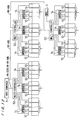
- FIG. 12 is a block diagram showing a vacuum pump control system which employs a series-connected array of multi-controllers 50 shown in FIGS. 8 through 10. As shown in FIG. 12, in the case where the number of vacuum pumps to be monitored and controlled exceeds the number of vacuum pumps that can be monitored and controlled by a single multi-controller 50, a plurality of multi-controllers 50 are connected in series by RS-485 cables for monitoring and controlling those vacuum pumps.
- FIG. 13 is a block diagram showing another vacuum pump control system which employs a parallel-connected array of multi-controllers 50 shown in FIGS. 8 through 10.
- a plurality of multi-controllers 50 are in parallel connected by RS-232C cables for monitoring and controlling a number of vacuum pumps.
- the multi-controllers 50 are connected to a distributor 300 which is connected to a host computer 4 through an RS-485 cable, for example.
- FIG. 14 shows a processing sequence of the multi-controller 50.
- the processing sequence starts in a step S1 when the power supply of the multi-controller 50 is turned on.
- a step S2 a memory of the multi-controller 50 is initialized and initial setting of peripheral devices connected thereto is performed. Then, whether interface cards, i.e., vacuum pump cards 54, 55, 56 and 57, are inserted in the slots 50S or not is checked in a step S3. If the interface cards are inserted in the slots 50S, then the types (cryopump, cryoturbo pump, turbomolecular pump, dry pump) of the interface cards are identified. In a step S4, a processing slot is set to a first one of the slots 50S.
- a step S5 transmission and receiving signals to and from an external device connected to the multi-controller 50 are carried out.
- step S6 signals from switches on the front panel of the multi-controller 50 are read.
- step S7 card information from the interface card inserted in the processing slot is read.
- step S8 whether the read card information represents a cryopump or not is identified. If the card information represents a cryopump, then the cryopump is started, stopped, monitored, or regenerated in a step S9. If the card information does not represent a cryopump in the step S8, then whether the read card information represents a cryoturbo pump or not is identified in a step S10.
- the cryoturbo pump is started, stopped, monitored, or regenerated in a step S11.
- peripheral devices associated with the cryoturbo pump are also monitored and controlled. If the card information does not represent a cryoturbo pump in the step S10, then whether the read card information represents a turbomolecular pump or not is identified in a step S12. If the card information represents a turbomolecular pump, then the turbomolecular pump is started, stopped, monitored, or regenerated in a step S13. If the card information does not represent a turbomolecular pump in the step S12, then whether the read card information represents a dry pump or not is identified in a step S14.
- the dry pump is started, stopped, monitored, or regenerated in a step S15. If the card information does not represent a dry pump, then since a pump type is unable to be identified from the card information, a card failure process is executed in a step S16.
- a step S17 data are displayed on the LCDs depending on a presently selected display menu, and the LEDs flicker depending on present operation statuses.
- a step S18 whether the present processing slot is a final one of the slots 50S or not, i.e., whether all the slots 50S have been processed or not is identified.
- the processing slot is shifted to a next one of the slots 50S in a step S19. If all the slots 50S have been processed, then the processing slot is returned to the first one of the slots 50S in a step S20.
- the vacuum pumps 10, 11, 12 and 13 can be monitored and controlled by the single multi-controller 50. Since the cards 54, 55, 56 and 57 are detachably inserted as control modules in the multi-controller 50, the vacuum pumps 10, 11, 12 and 13 which need to be monitored and controlled can be handled by a minimum amount of hardware provided by the cards 54, 55, 56 and 57. A plurality of different types of vacuum pumps and a plurality of vacuum pumps can thus be controlled by control modules which correspond to those different types of vacuum pumps.
Landscapes
- Engineering & Computer Science (AREA)
- General Engineering & Computer Science (AREA)
- Mechanical Engineering (AREA)
- Computer Hardware Design (AREA)
- Manufacturing & Machinery (AREA)
- Quality & Reliability (AREA)
- Physics & Mathematics (AREA)
- General Physics & Mathematics (AREA)
- Automation & Control Theory (AREA)
- Compressors, Vaccum Pumps And Other Relevant Systems (AREA)
- Control Of Positive-Displacement Pumps (AREA)
Applications Claiming Priority (3)
| Application Number | Priority Date | Filing Date | Title |
|---|---|---|---|
| JP149931/96 | 1996-05-21 | ||
| JP14993196 | 1996-05-21 | ||
| JP14993196 | 1996-05-21 |
Publications (2)
| Publication Number | Publication Date |
|---|---|
| EP0809164A1 true EP0809164A1 (de) | 1997-11-26 |
| EP0809164B1 EP0809164B1 (de) | 2001-09-05 |
Family
ID=15485702
Family Applications (1)
| Application Number | Title | Priority Date | Filing Date |
|---|---|---|---|
| EP97108201A Revoked EP0809164B1 (de) | 1996-05-21 | 1997-05-21 | Steuerungssystem zum Steuern mehrerer Vakuumpumpen |
Country Status (4)
| Country | Link |
|---|---|
| US (1) | US5971711A (de) |
| EP (1) | EP0809164B1 (de) |
| KR (1) | KR970075386A (de) |
| DE (1) | DE69706472T2 (de) |
Cited By (11)
| Publication number | Priority date | Publication date | Assignee | Title |
|---|---|---|---|---|
| US6272400B1 (en) | 1998-07-13 | 2001-08-07 | Helix Technology Corporation | Vacuum network controller |
| US6318091B1 (en) | 1999-10-28 | 2001-11-20 | Helix Technology Corporation | Cryopump system with modular electronics |
| US6671583B2 (en) | 2001-03-30 | 2003-12-30 | Helix Technology Corporation | Vacuum system information network |
| US7016751B2 (en) | 2001-07-13 | 2006-03-21 | Helix Technology Corporation | Vacuum system central control information server |
| EP2399272A1 (de) * | 2009-02-22 | 2011-12-28 | Mapper Lithography IP B.V. | Verfahren und anordnung zur realisierung eines vakuums in einer vakuumkammer |
| JP2012237293A (ja) * | 2011-05-13 | 2012-12-06 | Sumitomo Heavy Ind Ltd | クライオポンプシステム、クライオポンプのための再生方法 |
| EP1903530A3 (de) * | 2006-09-23 | 2014-09-17 | Pfeiffer Vacuum GmbH | Anordnung mit Vakuumgerät und Verfahren zu deren Betrieb |
| WO2018193376A1 (en) * | 2017-04-18 | 2018-10-25 | D.V.P. Vacuum Technology S.p.A. | Vacuum pump |
| EP3620661A1 (de) * | 2019-08-30 | 2020-03-11 | Pfeiffer Vacuum Gmbh | Anschlussvorrichtung, system und verfahren zum betreiben einer anschlussvorrichtung |
| EP3620663A1 (de) * | 2018-09-06 | 2020-03-11 | Pfeiffer Vacuum Gmbh | Vakuumvorrichtung |
| EP3543533A4 (de) * | 2016-11-17 | 2020-06-10 | Hangzhou Sanhua Research Institute Co., Ltd. | Steuerungssystem und steuerungsverfahren |
Families Citing this family (32)
| Publication number | Priority date | Publication date | Assignee | Title |
|---|---|---|---|---|
| JP3767052B2 (ja) * | 1996-11-30 | 2006-04-19 | アイシン精機株式会社 | 多段式真空ポンプ |
| US6045331A (en) * | 1998-08-10 | 2000-04-04 | Gehm; William | Fluid pump speed controller |
| EP1043645B1 (de) * | 1999-04-07 | 2004-10-20 | Alcatel | Druckregelvorrichtung für eine Vakuumkammer, und eine mit einer solchen Vorrichtung versehenen Vakuumpumpeinheit |
| TW470815B (en) * | 1999-04-30 | 2002-01-01 | Arumo Technos Kk | Method and apparatus for controlling a vacuum pump |
| FR2808098B1 (fr) * | 2000-04-20 | 2002-07-19 | Cit Alcatel | Procede et dispositif de conditionnement de l'atmosphere dans une chambre de procedes |
| JP4280003B2 (ja) * | 2001-05-31 | 2009-06-17 | 株式会社日立製作所 | 遠隔保守方法および産業用機器 |
| KR100385917B1 (ko) * | 2001-06-27 | 2003-06-02 | 삼성전자주식회사 | 이온 주입 시스템의 진공 펌핑 장치 |
| US7127901B2 (en) | 2001-07-20 | 2006-10-31 | Brooks Automation, Inc. | Helium management control system |
| DE10208676A1 (de) * | 2002-02-28 | 2003-09-04 | Man Turbomasch Ag Ghh Borsig | Verfahren zum Regeln von mehreren Strömungsmaschinen im Parallel- oder Reihenbetrieb |
| US20030175112A1 (en) * | 2002-03-13 | 2003-09-18 | Hirotaka Namiki | Vacuum pump system and vacuum pump RPM control method |
| US6739840B2 (en) * | 2002-05-22 | 2004-05-25 | Applied Materials Inc | Speed control of variable speed pump |
| KR100475184B1 (ko) * | 2002-05-23 | 2005-03-08 | 신한일전기주식회사 | 가압급수장치의 원격제어방법 |
| EP1649166B1 (de) * | 2003-06-27 | 2007-02-28 | Helix Technology Corporation | Integration einer automatisierten kryopumpensicherheitsspülung |
| DE602004005154T2 (de) * | 2004-03-15 | 2007-11-08 | Varian S.P.A., Leini | Vakuumpumpenanlage |
| US7886692B2 (en) * | 2004-07-13 | 2011-02-15 | Delaval Holding Ab | Controllable vacuum source |
| DE102004056246C5 (de) * | 2004-11-22 | 2014-07-31 | Abb Ag | Anzeigeeinrichtung für ein Elektronikgerät |
| CN100507269C (zh) * | 2005-11-02 | 2009-07-01 | 旺宏电子股份有限公司 | 真空抽气装置 |
| JP4737770B2 (ja) * | 2006-09-12 | 2011-08-03 | アネスト岩田株式会社 | 真空ポンプの運転制御装置および方法 |
| US20080078189A1 (en) * | 2006-09-28 | 2008-04-03 | Sumitomo Heavy Industries, Ltd. | Communication network system |
| US20090053072A1 (en) * | 2007-08-21 | 2009-02-26 | Justin Borgstadt | Integrated "One Pump" Control of Pumping Equipment |
| GB2453120B (en) * | 2007-09-26 | 2009-09-02 | Siemens Magnet Technology Ltd | Intelligent helium compressor |
| JP5210147B2 (ja) * | 2008-01-24 | 2013-06-12 | 株式会社荏原製作所 | 給水装置 |
| CH703478A1 (de) * | 2010-07-30 | 2012-01-31 | Medela Holding Ag | Absaugpumpensystem. |
| CN103267009B (zh) * | 2013-05-29 | 2016-08-24 | 赖正伦 | 一种高效蓄能输送系统 |
| JP2016153617A (ja) * | 2015-02-20 | 2016-08-25 | 住友重機械工業株式会社 | クライオポンプシステム、クライオポンプ制御装置、及びクライオポンプ再生方法 |
| CN105952659A (zh) * | 2016-05-09 | 2016-09-21 | 湖南耐普泵业股份有限公司 | 智能永磁电泵机组及其控制方法 |
| KR101927985B1 (ko) | 2017-09-29 | 2019-02-26 | 심준우 | 진공펌프시스템의 공정을 위한 무선원격제어시스템 |
| CN108614493A (zh) * | 2018-06-13 | 2018-10-02 | 重庆金鹰自动化工程有限公司 | 一种实现超真空状态的冷凝头控制系统 |
| JP7299098B2 (ja) * | 2018-08-06 | 2023-06-27 | エドワーズ株式会社 | 除害システム、除害装置、およびシステム制御装置 |
| JP7554648B2 (ja) * | 2020-11-25 | 2024-09-20 | 住友重機械工業株式会社 | クライオポンプシステムおよびその監視方法 |
| CN115312363B (zh) * | 2022-07-19 | 2024-12-13 | 中国科学院上海高等研究院 | 一种用于加速器隧道内低温传输线的高真空系统 |
| US12560160B2 (en) * | 2022-10-07 | 2026-02-24 | Keco Inc. | Pump controller assembly |
Citations (4)
| Publication number | Priority date | Publication date | Assignee | Title |
|---|---|---|---|---|
| US4319338A (en) * | 1979-12-12 | 1982-03-09 | Allen-Bradley Company | Industrial communications network with mastership determined by need |
| US5050397A (en) * | 1989-07-28 | 1991-09-24 | Kabushiki Kaisha Toshiba | Air conditioner apparatus with starting control for parallel operated compressors based on high pressure detection |
| WO1993005859A1 (en) * | 1991-09-19 | 1993-04-01 | The United States Of America, As Represented By The Secretary Of The Department Of Health And Human Services | Miniature cryosorption vacuum pump |
| US5305467A (en) * | 1990-12-03 | 1994-04-19 | Ericsson Ge Mobile Communications Inc. | Local area network for flexible digital communications within and between RF base stations |
Family Cites Families (7)
| Publication number | Priority date | Publication date | Assignee | Title |
|---|---|---|---|---|
| US4876664A (en) * | 1987-08-26 | 1989-10-24 | Allen-Bradley Company, Inc. | Programmable controller with a dual intermodule message system |
| US4918930A (en) * | 1988-09-13 | 1990-04-24 | Helix Technology Corporation | Electronically controlled cryopump |
| US5157928A (en) * | 1988-09-13 | 1992-10-27 | Helix Technology Corporation | Electronically controlled cryopump |
| US5176004A (en) * | 1991-06-18 | 1993-01-05 | Helix Technology Corporation | Electronically controlled cryopump and network interface |
| US5375424A (en) * | 1993-02-26 | 1994-12-27 | Helix Technology Corporation | Cryopump with electronically controlled regeneration |
| JP3847357B2 (ja) * | 1994-06-28 | 2006-11-22 | 株式会社荏原製作所 | 真空系の排気装置 |
| US5586050A (en) * | 1994-08-10 | 1996-12-17 | Aerojet General Corp. | Remotely controllable LNG field station management system and method |
-
1997
- 1997-05-19 US US08/858,622 patent/US5971711A/en not_active Expired - Fee Related
- 1997-05-21 KR KR1019970019649A patent/KR970075386A/ko not_active Ceased
- 1997-05-21 DE DE69706472T patent/DE69706472T2/de not_active Revoked
- 1997-05-21 EP EP97108201A patent/EP0809164B1/de not_active Revoked
Patent Citations (4)
| Publication number | Priority date | Publication date | Assignee | Title |
|---|---|---|---|---|
| US4319338A (en) * | 1979-12-12 | 1982-03-09 | Allen-Bradley Company | Industrial communications network with mastership determined by need |
| US5050397A (en) * | 1989-07-28 | 1991-09-24 | Kabushiki Kaisha Toshiba | Air conditioner apparatus with starting control for parallel operated compressors based on high pressure detection |
| US5305467A (en) * | 1990-12-03 | 1994-04-19 | Ericsson Ge Mobile Communications Inc. | Local area network for flexible digital communications within and between RF base stations |
| WO1993005859A1 (en) * | 1991-09-19 | 1993-04-01 | The United States Of America, As Represented By The Secretary Of The Department Of Health And Human Services | Miniature cryosorption vacuum pump |
Cited By (13)
| Publication number | Priority date | Publication date | Assignee | Title |
|---|---|---|---|---|
| US6272400B1 (en) | 1998-07-13 | 2001-08-07 | Helix Technology Corporation | Vacuum network controller |
| US6318091B1 (en) | 1999-10-28 | 2001-11-20 | Helix Technology Corporation | Cryopump system with modular electronics |
| US6474080B2 (en) | 1999-10-28 | 2002-11-05 | Helix Technology Corporation | Cryopump system with modular electronics |
| US6671583B2 (en) | 2001-03-30 | 2003-12-30 | Helix Technology Corporation | Vacuum system information network |
| US7016751B2 (en) | 2001-07-13 | 2006-03-21 | Helix Technology Corporation | Vacuum system central control information server |
| EP1903530A3 (de) * | 2006-09-23 | 2014-09-17 | Pfeiffer Vacuum GmbH | Anordnung mit Vakuumgerät und Verfahren zu deren Betrieb |
| EP2399272A1 (de) * | 2009-02-22 | 2011-12-28 | Mapper Lithography IP B.V. | Verfahren und anordnung zur realisierung eines vakuums in einer vakuumkammer |
| JP2012237293A (ja) * | 2011-05-13 | 2012-12-06 | Sumitomo Heavy Ind Ltd | クライオポンプシステム、クライオポンプのための再生方法 |
| EP3543533A4 (de) * | 2016-11-17 | 2020-06-10 | Hangzhou Sanhua Research Institute Co., Ltd. | Steuerungssystem und steuerungsverfahren |
| US10989187B2 (en) | 2016-11-17 | 2021-04-27 | Hangzhou Sanhua Research Institute Co., Ltd. | Control system and control method |
| WO2018193376A1 (en) * | 2017-04-18 | 2018-10-25 | D.V.P. Vacuum Technology S.p.A. | Vacuum pump |
| EP3620663A1 (de) * | 2018-09-06 | 2020-03-11 | Pfeiffer Vacuum Gmbh | Vakuumvorrichtung |
| EP3620661A1 (de) * | 2019-08-30 | 2020-03-11 | Pfeiffer Vacuum Gmbh | Anschlussvorrichtung, system und verfahren zum betreiben einer anschlussvorrichtung |
Also Published As
| Publication number | Publication date |
|---|---|
| EP0809164B1 (de) | 2001-09-05 |
| KR970075386A (ko) | 1997-12-10 |
| US5971711A (en) | 1999-10-26 |
| DE69706472D1 (de) | 2001-10-11 |
| DE69706472T2 (de) | 2002-05-16 |
Similar Documents
| Publication | Publication Date | Title |
|---|---|---|
| US5971711A (en) | Vacuum pump control system | |
| US7413411B2 (en) | Electronically controlled vacuum pump | |
| US6461113B1 (en) | Electronically controlled vacuum pump | |
| US6755028B2 (en) | Electronically controlled cryopump | |
| EP0553935B1 (de) | Elektronisch gesteuerte Kryopumpe | |
| US5443368A (en) | Turbomolecular pump with valves and integrated electronic controls | |
| US5176004A (en) | Electronically controlled cryopump and network interface | |
| US5157928A (en) | Electronically controlled cryopump | |
| EP1577559B1 (de) | Vakuumpumpenanlage | |
| JPH1054369A (ja) | 真空ポンプの制御装置 | |
| US6438973B1 (en) | Control board alarms | |
| JP2022083523A (ja) | クライオポンプシステムおよびその監視方法 | |
| JP2000065415A (ja) | 空気調和機 | |
| JP4006101B2 (ja) | 真空ポンプの制御装置 | |
| JP3054556B2 (ja) | ショーケースの集中制御装置 | |
| JP2007085610A (ja) | 集中管理システム | |
| JP2752289B2 (ja) | ショーケース等の集中管理装置 | |
| KR0130415B1 (ko) | 냉동기용 제어장치 | |
| JPH09236368A (ja) | ショーケース等の集中管理装置 | |
| JPH08247600A (ja) | ショーケース等の集中管理装置 | |
| JPH0861822A (ja) | ショーケース等の集中管理装置 | |
| JPH05264147A (ja) | ショーケース等の集中管理装置 | |
| JPH0829044A (ja) | ショーケース等の集中管理装置 |
Legal Events
| Date | Code | Title | Description |
|---|---|---|---|
| PUAI | Public reference made under article 153(3) epc to a published international application that has entered the european phase |
Free format text: ORIGINAL CODE: 0009012 |
|
| AK | Designated contracting states |
Kind code of ref document: A1 Designated state(s): DE GB |
|
| 17P | Request for examination filed |
Effective date: 19980518 |
|
| 17Q | First examination report despatched |
Effective date: 19980713 |
|
| GRAG | Despatch of communication of intention to grant |
Free format text: ORIGINAL CODE: EPIDOS AGRA |
|
| GRAG | Despatch of communication of intention to grant |
Free format text: ORIGINAL CODE: EPIDOS AGRA |
|
| GRAH | Despatch of communication of intention to grant a patent |
Free format text: ORIGINAL CODE: EPIDOS IGRA |
|
| GRAH | Despatch of communication of intention to grant a patent |
Free format text: ORIGINAL CODE: EPIDOS IGRA |
|
| GRAA | (expected) grant |
Free format text: ORIGINAL CODE: 0009210 |
|
| AK | Designated contracting states |
Kind code of ref document: B1 Designated state(s): DE GB |
|
| REF | Corresponds to: |
Ref document number: 69706472 Country of ref document: DE Date of ref document: 20011011 |
|
| REG | Reference to a national code |
Ref country code: GB Ref legal event code: IF02 |
|
| PGFP | Annual fee paid to national office [announced via postgrant information from national office to epo] |
Ref country code: GB Payment date: 20020503 Year of fee payment: 6 |
|
| PGFP | Annual fee paid to national office [announced via postgrant information from national office to epo] |
Ref country code: DE Payment date: 20020531 Year of fee payment: 6 |
|
| PLBQ | Unpublished change to opponent data |
Free format text: ORIGINAL CODE: EPIDOS OPPO |
|
| PLBI | Opposition filed |
Free format text: ORIGINAL CODE: 0009260 |
|
| PLBF | Reply of patent proprietor to notice(s) of opposition |
Free format text: ORIGINAL CODE: EPIDOS OBSO |
|
| 26 | Opposition filed |
Opponent name: PFEIFFER VACUUM GMBH Effective date: 20020601 |
|
| PLBF | Reply of patent proprietor to notice(s) of opposition |
Free format text: ORIGINAL CODE: EPIDOS OBSO |
|
| RDAH | Patent revoked |
Free format text: ORIGINAL CODE: EPIDOS REVO |
|
| RDAG | Patent revoked |
Free format text: ORIGINAL CODE: 0009271 |
|
| STAA | Information on the status of an ep patent application or granted ep patent |
Free format text: STATUS: PATENT REVOKED |
|
| 27W | Patent revoked |
Effective date: 20021205 |
|
| GBC | Gb: translation of claims filed (gb section 78(7)/1977) |
Free format text: 20021205 |