EP0809266A2 - Appareil de commutation à basse tension - Google Patents
Appareil de commutation à basse tension Download PDFInfo
- Publication number
- EP0809266A2 EP0809266A2 EP97108101A EP97108101A EP0809266A2 EP 0809266 A2 EP0809266 A2 EP 0809266A2 EP 97108101 A EP97108101 A EP 97108101A EP 97108101 A EP97108101 A EP 97108101A EP 0809266 A2 EP0809266 A2 EP 0809266A2
- Authority
- EP
- European Patent Office
- Prior art keywords
- switching
- switching device
- contacts
- contact
- rocker
- Prior art date
- Legal status (The legal status is an assumption and is not a legal conclusion. Google has not performed a legal analysis and makes no representation as to the accuracy of the status listed.)
- Withdrawn
Links
- 239000011324 bead Substances 0.000 claims description 4
- 239000003086 colorant Substances 0.000 claims description 3
- 238000007373 indentation Methods 0.000 claims description 2
- 230000006835 compression Effects 0.000 description 3
- 238000007906 compression Methods 0.000 description 3
- 238000011161 development Methods 0.000 description 3
- 230000018109 developmental process Effects 0.000 description 3
- 238000004519 manufacturing process Methods 0.000 description 3
- 230000011664 signaling Effects 0.000 description 2
- 241000269350 Anura Species 0.000 description 1
- 230000001419 dependent effect Effects 0.000 description 1
- 230000036039 immunity Effects 0.000 description 1
- 238000009413 insulation Methods 0.000 description 1
Images

Classifications
-
- H—ELECTRICITY
- H01—ELECTRIC ELEMENTS
- H01H—ELECTRIC SWITCHES; RELAYS; SELECTORS; EMERGENCY PROTECTIVE DEVICES
- H01H23/00—Tumbler or rocker switches, i.e. switches characterised by being operated by rocking an operating member in the form of a rocker button
- H01H23/02—Details
- H01H23/08—Bases; Stationary contacts mounted thereon
-
- H—ELECTRICITY
- H01—ELECTRIC ELEMENTS
- H01H—ELECTRIC SWITCHES; RELAYS; SELECTORS; EMERGENCY PROTECTIVE DEVICES
- H01H23/00—Tumbler or rocker switches, i.e. switches characterised by being operated by rocking an operating member in the form of a rocker button
- H01H23/02—Details
- H01H23/025—Light-emitting indicators
-
- H—ELECTRICITY
- H01—ELECTRIC ELEMENTS
- H01H—ELECTRIC SWITCHES; RELAYS; SELECTORS; EMERGENCY PROTECTIVE DEVICES
- H01H23/00—Tumbler or rocker switches, i.e. switches characterised by being operated by rocking an operating member in the form of a rocker button
- H01H23/28—Tumbler or rocker switches, i.e. switches characterised by being operated by rocking an operating member in the form of a rocker button with three operating positions
- H01H23/30—Tumbler or rocker switches, i.e. switches characterised by being operated by rocking an operating member in the form of a rocker button with three operating positions with stable centre positions and one or both end positions unstable
-
- H—ELECTRICITY
- H01—ELECTRIC ELEMENTS
- H01H—ELECTRIC SWITCHES; RELAYS; SELECTORS; EMERGENCY PROTECTIVE DEVICES
- H01H23/00—Tumbler or rocker switches, i.e. switches characterised by being operated by rocking an operating member in the form of a rocker button
- H01H23/003—Tumbler or rocker switches, i.e. switches characterised by being operated by rocking an operating member in the form of a rocker button with more than one electrically distinguishable condition in one or both positions
Definitions
- the invention relates to a monostable low-voltage switching device with a rest position and at least one working position, with a housing, with a manual actuating element, which cooperates with a rocker switch and is articulated on the housing, which rocker switch acts on at least one switching contact designed as a contact spring, which can be connected to an associated fixed contact is.
- Monostable electrical switching devices with rocker switches for actuating contact points are generally known as buttons.
- the rocking movement connects a movable contact to a fixed contact for the duration of the actuation, or disconnects it from it, if it is a quiescent current button.
- the button After releasing the rocker switch or the assigned actuating element, the button returns to its rest position.
- a special form of a push button provides the use of contact springs as a switching contact, in which the return spring of the movable contact is integrated in this.
- contact springs which are also referred to as "crack frogs" usually have a domed surface which are acted upon against the direction of the arch and are automatically reset by self-resilience.
- buttons in particular rocker buttons, only ever have an electrical switching function in the direction of their rocking or swiveling movement, namely closing or opening a contact point. If several functions are required, several such buttons have hitherto been arranged side by side or one behind the other, on which the different switching functions are divided, for example in the case of sound recording devices, such as tape recorders, playback and fast forwarding.
- two switching contacts are accordingly provided in each working position, which are arranged offset from one another and can be acted upon in stages by the manual actuation element. This ensures that different command signals are transmitted in each switching stage, with the operations that take place in second place overlaying the first one.
- the switching device has two working positions, so that a total of four switching contacts can be acted upon alternately, each of which is assigned to one another in pairs.
- the switch contacts are preferably designed as contact springs, not least for reasons of the compactness to be sought, that is to say of a small size. This enables the contact points to be arranged in a very small space, insulation problems not occurring because of the predetermined low voltage, preferably ⁇ 50 V.
- control currents are primarily switched by means of the switching device according to the invention, so that the contact load on the switching contacts is likewise comparatively low.
- the preferred field of application of the switching device according to the invention is vehicle electrics for switching electrical seat adjusters, electrical window regulators, electrical exterior mirrors or electrical sliding / lifting roofs.
- vehicle electrics for switching electrical seat adjusters, electrical window regulators, electrical exterior mirrors or electrical sliding / lifting roofs.
- electrical household technology for example electrical armchair or bed adjustments
- consumer electronics for example in magnetic recording devices, such as video recorders, and the switching functions resulting therefrom with the switching device according to the invention.
- a preferred embodiment of the invention provides that the switch contacts are arranged on a circuit board which is inserted in the housing. This allows inexpensive and assembly-friendly production.
- the fixed contacts can be injected into the housing or inserted in a force-fitting and / or form-fitting manner.
- the fixed contacts are arranged hanging in the circuit board.
- the printed circuit board can be provided with recesses in which the switch contacts engage with retaining webs for their attachment.
- the retaining webs of the switch contacts are advantageously provided with beads, which are used for the form-fitting attachment of the switch contacts to the circuit board and engage behind them through the recesses.
- the recesses can be opposite each other in the housing assigned blind holes can be provided, in which the retaining webs of the switching contacts which protrude from the printed circuit board engage.
- a signal device can be provided, which optionally serves as a switch position indicator or as an orientation aid.
- the signal device serving as a switch position indicator is advantageously formed by a light-emitting diode to which a series resistor is assigned if necessary.
- the light-emitting diode can be formed by a duo light-emitting diode with two different colors, which indicate the respective switching position.
- the signal device formed by the light-emitting diode and the optionally associated series resistor can be arranged on the printed circuit board. It is advantageous if the signal device is arranged between the switching contacts below the rocker switch, in which case the rocker switch, which is integrated in the actuating element, is designed to be translucent above the signal device, so that the corresponding signal of the signal device can also be perceived visually.
- the rocker switch has an actuating plunger for each switching contact, the actuating plunger adjacent to the pivot axis being acted upon by a spring.
- each switch contact has a central indentation for centering the associated actuating plunger, which acts on the switch contact at this point as intended.
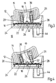
- FIG. 1 shows a longitudinal section through an inventive low-voltage switching device 10 with a housing 12, with an actuating element 14 in the rest position.
- the actuating element is designed as a rocker button 14, which can be pivoted about a pivot axis 15 and is used with a total of two first switching plungers 18, 19 and two second switching plungers 20, 21 for the optional actuation of four switching contacts 22, 24, 26, 28.
- the switch contacts 22, 24, 26, 28 are arranged on a circuit board 16 inserted into the housing 12 and, as can be seen from the plan view shown in FIG. 2, are positioned at an angle to one another.
- the first two switching plungers 18, 19 are provided with pressure pieces 32 acted upon by compression springs 30, which each rest on the assigned switching contacts 18, 19 in the rest position, but without actuating them.
- the spring force of the compression spring 30 is set so that it exceeds the restoring force of the switching contacts 22, 24, 26, 28 designed as contact springs, so that when the rocker button 14 is pivoted toward one of the two sides, the first switching contact 22, 24 initially acted on as a result of this the spring loaded Thrust piece 32 reaches its switching position from its rest position, as shown in FIG. 3, and only resets itself automatically when this load is released.
- the second switching plunger 20, 21 assigned to this side of the rocker button 14 acts on the correspondingly assigned second switching contact 26, 28 while simultaneously acting on the assigned first switching contact 22, 24.
- the circuit board 16 there are also at least one signal device 34 formed here by an LED and in each case an associated series resistor 36, which can optionally be used to display the respective switching position, for example by different colors, or serve the position of the switching device 10.
- the switching rocker 14 practically completely overlapping the circuit board is designed to be transparent or translucent in the central region closest to the signaling device, so that the light signal emitted by the signaling device 34 can be clearly recognized from the outside.
- the switching contacts 22, 24, 26, 28 are designed as automatically resetting contact springs with an approximately circular plan, with contact arms 38 designed as retaining webs at three points arranged in a star shape on the edge of each contact spring 22, 24 are formed at right angles to the plane of the board, which engage in recesses 40 provided for this purpose in the board 16 and are attached to the board 16 by means of beads 42 integrally formed on the contact arms 38.
- the beads 42 engage behind the recesses and lie against the underside of the circuit board 16.
- electrical connections 44 in the form of fixed contacts are provided, which engage in the circuit board 16 from below and are soldered to it, via which fixed contacts 44 the individual switching contacts 22, 24, 26, 28 of the switching device 10 with the associated, Consumer not shown here or connected to the power source, also not shown.
- the mode of operation of the switching device 10 according to the invention is based on the fact that a two-stage switching is hereby possible in that the rocker switch 14 can be actuated in two clearly perceptible switching stages on each side and thereby switches on or off two electrically independent circuits.
- first switching plungers 18, 19 are designed to be variable in length using the compression spring 30 without falling below the force required for switching actuation, so that both the first switching plunger 18, 19 and the second switching plunger when the rocker switch 14 is pivoted accordingly 20, 21 actuate the associated switch contact 22, 24, 26, 28.
Landscapes
- Rotary Switch, Piano Key Switch, And Lever Switch (AREA)
- Tumbler Switches (AREA)
Applications Claiming Priority (2)
| Application Number | Priority Date | Filing Date | Title |
|---|---|---|---|
| DE19621192 | 1996-05-25 | ||
| DE1996121192 DE19621192A1 (de) | 1996-05-25 | 1996-05-25 | Niederspannungsschaltgerät |
Publications (2)
| Publication Number | Publication Date |
|---|---|
| EP0809266A2 true EP0809266A2 (fr) | 1997-11-26 |
| EP0809266A3 EP0809266A3 (fr) | 1998-11-04 |
Family
ID=7795367
Family Applications (1)
| Application Number | Title | Priority Date | Filing Date |
|---|---|---|---|
| EP97108101A Withdrawn EP0809266A3 (fr) | 1996-05-25 | 1997-05-20 | Appareil de commutation à basse tension |
Country Status (2)
| Country | Link |
|---|---|
| EP (1) | EP0809266A3 (fr) |
| DE (1) | DE19621192A1 (fr) |
Cited By (2)
| Publication number | Priority date | Publication date | Assignee | Title |
|---|---|---|---|---|
| WO2005041361A1 (fr) * | 2003-10-15 | 2005-05-06 | Tyco Electronics Amp Gmbh | Connecteur electrique pour conducteur plat flexible et dispositif commutateur |
| EP1921644A3 (fr) * | 2006-11-10 | 2009-02-11 | Gamesman Limited | Interrupteur à bascule OLED |
Families Citing this family (5)
| Publication number | Priority date | Publication date | Assignee | Title |
|---|---|---|---|---|
| DE19918578A1 (de) * | 1999-04-23 | 2000-10-26 | Abb Patent Gmbh | Monostabiler zweiseitiger Wippen-Taster |
| DE19947965C2 (de) * | 1999-10-05 | 2003-04-24 | Bosch Gmbh Robert | Kraftfahrzeug-Steuervorrichtung und Verfahren zum Steuern einer Kraftfahrzeug-Funktion |
| JP3758129B2 (ja) * | 1999-10-15 | 2006-03-22 | 矢崎総業株式会社 | スイッチ装置 |
| DE102004036844B4 (de) * | 2004-07-29 | 2007-11-08 | Bj Automotive Gmbh | Wippschalter |
| DE102008051228B4 (de) * | 2008-10-10 | 2016-08-04 | Leopold Kostal Gmbh & Co. Kg | Wippschalter und Auswertevorrichtung mit einem Wippschalter |
Family Cites Families (8)
| Publication number | Priority date | Publication date | Assignee | Title |
|---|---|---|---|---|
| DE7315639U (de) * | 1973-04-25 | 1973-08-16 | Baer Elektrowerke Kg | Elektrischer Schalter, insbesondere Wippenschalter |
| DE2848588C2 (de) * | 1978-11-09 | 1982-09-09 | Daut & Rietz KG Fabrik für Elektrofeinmechanik GmbH & Co, 8500 Nürnberg | Tipptaste |
| US4301378A (en) * | 1979-11-29 | 1981-11-17 | Motorola, Inc. | Dual rate bi-directional switch |
| DE3818810A1 (de) * | 1988-06-03 | 1989-12-14 | Asea Brown Boveri | Elektrischer tastschalter |
| CH677552A5 (fr) * | 1989-04-10 | 1991-05-31 | Sulzer Ag | |
| DE9212062U1 (de) * | 1992-09-08 | 1992-10-29 | Abb Patent Gmbh, 68309 Mannheim | Wipptaster |
| DE4242100B4 (de) * | 1992-12-14 | 2004-02-05 | Abb Patent Gmbh | Elektrisches Schaltgerät |
| US5453731A (en) * | 1993-11-22 | 1995-09-26 | Chrysler Corporation | Automotive switch lighted with integral diodes |
-
1996
- 1996-05-25 DE DE1996121192 patent/DE19621192A1/de not_active Withdrawn
-
1997
- 1997-05-20 EP EP97108101A patent/EP0809266A3/fr not_active Withdrawn
Cited By (2)
| Publication number | Priority date | Publication date | Assignee | Title |
|---|---|---|---|---|
| WO2005041361A1 (fr) * | 2003-10-15 | 2005-05-06 | Tyco Electronics Amp Gmbh | Connecteur electrique pour conducteur plat flexible et dispositif commutateur |
| EP1921644A3 (fr) * | 2006-11-10 | 2009-02-11 | Gamesman Limited | Interrupteur à bascule OLED |
Also Published As
| Publication number | Publication date |
|---|---|
| EP0809266A3 (fr) | 1998-11-04 |
| DE19621192A1 (de) | 1997-11-27 |
Similar Documents
| Publication | Publication Date | Title |
|---|---|---|
| DE69408418T2 (de) | Hebelschaltervorrichtung, Verfahren zur Steuerung von Schaltern in solcher Vorrichtung und Verfahren zum Ausgeben von Datensignalen | |
| EP0234193A2 (fr) | Agencement d'interrupteur | |
| DE19620235B4 (de) | Schalter für insbesondere einen elektrischen Fahrzeug-Fensterheber | |
| DE19722709A1 (de) | Schaltvorrichtung | |
| DE19955070A1 (de) | Schalteranordnung für ein Kraftfahrzeug | |
| DE3613702C2 (fr) | ||
| DE60032045T2 (de) | Zusammengesetzter Schalter | |
| DE1920784A1 (de) | Schiebeschalter fuer Geraete mit einem von einer Isolierstoffplatte getragenen Leiternetz | |
| EP0809266A2 (fr) | Appareil de commutation à basse tension | |
| EP0817226A2 (fr) | Interrupteur à bascule | |
| DE60303546T2 (de) | Schaltvorrichtung | |
| DE3129210C2 (de) | Elektrische Schaltvorrichtung | |
| DE3835073C2 (de) | Elektrischer Schalter für eine Kraftfahrzeug-Fensterhebevorrichtung | |
| EP0974718A3 (fr) | Actionneur à moteur électrique pour des serrures de véhicule automobile | |
| EP0884744A2 (fr) | Commutateur à poussoir monostabile | |
| EP0341416B1 (fr) | Dispositif interrupteur | |
| DE2452944C3 (de) | Tastenschaltersystem | |
| DE102007009006B4 (de) | Tastschalter für ein Kraftfahrzeug | |
| EP0602462B1 (fr) | Appareillage électrique | |
| EP0620577B1 (fr) | Interrupteur à bouton-poussoir | |
| DE3688027T2 (de) | Elektrische ferngesteuerte Anlagen. | |
| DE2224889A1 (de) | Schaltsystem zur Anzeige von Warnsignalen bei Kraftfahrzeugen | |
| EP1196311B1 (fr) | Systeme pour actionner des elements fonctionnels electriques | |
| EP0170958B1 (fr) | Relais piézoélectrique | |
| DE10113031A1 (de) | Elektromotorischer Möbelantrieb zur Verstellung von Teilen eines Möbels relativ zueinender |
Legal Events
| Date | Code | Title | Description |
|---|---|---|---|
| PUAI | Public reference made under article 153(3) epc to a published international application that has entered the european phase |
Free format text: ORIGINAL CODE: 0009012 |
|
| AK | Designated contracting states |
Kind code of ref document: A2 Designated state(s): DE ES FR GB IT PT |
|
| PUAL | Search report despatched |
Free format text: ORIGINAL CODE: 0009013 |
|
| AK | Designated contracting states |
Kind code of ref document: A3 Designated state(s): DE ES FR GB IT PT |
|
| 17P | Request for examination filed |
Effective date: 19990619 |
|
| RAP1 | Party data changed (applicant data changed or rights of an application transferred) |
Owner name: ABB PATENT GMBH |
|
| 17Q | First examination report despatched |
Effective date: 20011024 |
|
| STAA | Information on the status of an ep patent application or granted ep patent |
Free format text: STATUS: THE APPLICATION HAS BEEN WITHDRAWN |
|
| 18W | Application withdrawn |
Withdrawal date: 20020416 |