EP0809368A1 - Optisches Übertragungssystem mit optischen Verstärkern und Verstärkung abhängig von der Eingangssignalpolarisation - Google Patents
Optisches Übertragungssystem mit optischen Verstärkern und Verstärkung abhängig von der Eingangssignalpolarisation Download PDFInfo
- Publication number
- EP0809368A1 EP0809368A1 EP97401083A EP97401083A EP0809368A1 EP 0809368 A1 EP0809368 A1 EP 0809368A1 EP 97401083 A EP97401083 A EP 97401083A EP 97401083 A EP97401083 A EP 97401083A EP 0809368 A1 EP0809368 A1 EP 0809368A1
- Authority
- EP
- European Patent Office
- Prior art keywords
- polarization
- optical
- modulation
- wavelength
- phase
- Prior art date
- Legal status (The legal status is an assumption and is not a legal conclusion. Google has not performed a legal analysis and makes no representation as to the accuracy of the status listed.)
- Granted
Links
Images
Classifications
-
- H—ELECTRICITY
- H04—ELECTRIC COMMUNICATION TECHNIQUE
- H04B—TRANSMISSION
- H04B10/00—Transmission systems employing electromagnetic waves other than radio-waves, e.g. infrared, visible or ultraviolet light, or employing corpuscular radiation, e.g. quantum communication
- H04B10/50—Transmitters
- H04B10/516—Details of coding or modulation
- H04B10/532—Polarisation modulation
Definitions
- the invention relates to an optical telecommunications system.
- Such a system includes optical conductors transmitting optical signals emitted by one or more laser sources, the amplitude of which is modulated by the signal to be transmitted.
- This signal is most often a telephone signal or a data signal.
- the advantage of optical transmission is low signal distortion and low attenuation. However, the attenuation is not zero; it is always felt over long distances. This is why in optical telecommunication systems, there are provided, from place to place, repeaters intended to amplify the naturally attenuated optical signal.
- An optical amplifier is generally formed by a doped optical fiber, for example by erbium Er +++ ions, and by a pumping laser intended to effect the population inversion of the electrons in the fiber, this inversion allowing the amplification effect.
- the input optical signal is polarized, it can be amplified anisotropically by the amplifier because the gain is lower in the signal polarization direction than in the orthogonal direction. In other words, the amplifier saturates more strongly in the direction of polarization of the signal than in the orthogonal direction.
- optical amplifiers This property of optical amplifiers is a drawback found in all optical telecommunication systems since, in these, the optical signal is produced by a laser providing a polarized wave.
- a polarizer which imposes a determined direction on polarization, and an electro-optical phase modulator receiving the signal polarized at 45 ° relative to the axes of the modulator crystal.
- the control voltage applied to the crystal periodically changes its refractive index. This variation in index, which is not the same for the two axes of the crystal, is carried out over a period less than the saturation time of the amplifier. It produces a phase shift between the components of the polarization vector on the two axes of the crystal. This phase shift causes the rotation of the polarization vector and therefore "scrambling" of this polarization.
- the gain of the amplifier is thus made isotropic.
- the invention aims to simplify the implementation of polarization interference.
- a phase or wavelength modulator which supplies a modulated signal to a means polarization dispersion, such as an optical fiber, in particular of the polarization maintaining type.
- the modulation is chosen as in patent 9401894, that is to say with a period less than the saturation time of the optical amplifiers.
- the polarization dispersion transforms the phase or wavelength modulation into polarization modulation and the desired polarization interference is therefore obtained.
- the invention considerably simplifies the production of the jammer, either by eliminating a polarizer (compared to the technique described in French patent 9401894), or by removing a modulator (compared to US patent 5,361,270).
- the polarization interference requires only the use of a phase or wavelength modulation, the polarization dispersion being obtained naturally in the optical communication fibers downstream of the modulator. .
- the communication fibers have negligible polarization dispersion, at least one portion of fiber having sufficient dispersion to introduce the desired interference is introduced downstream of the modulator.
- such a fiber is arranged from place to place, in particular in each repeater.
- the installation of such a fiber brings a negligible constraint for the realization of the system.
- the phase or wavelength modulator is downstream of the laser transmitter.
- no specific phase or wavelength modulator is provided but, instead, the wavelength of the emission laser is modulated. This modulation will also be performed with a period less than the saturation time of the optical amplifiers.
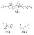
- the optical communication system represented in FIG. 1 comprises, in a manner known per se, a laser transmitter 10 producing a polarized monochromatic optical wave which is transmitted to an amplitude modulator 11, receiving on an input 12, control signals supplied by a generator 13 intended to modulate the amplitude of the optical signal.
- the modulation is digital. It represents the information to be transmitted, for example telephone communications.
- the signals at the output 14 of the modulator 11 are intended to be transmitted over a long distance, most often thousands of kilometers, by optical fibers 15 to one or more installations or reception centers 16.
- These repeaters are, for example, at constant power.
- the optical amplifiers of the repeaters 17, 18 are doped fiber amplifiers whose gain depends on the polarization of the input signal, as seen above.
- a device 20 for polarization scrambling which depolarizes, at least in large part, the optical signal supplied to the repeaters 17, 18 ...
- the jammer 20 comprises, on the one hand, a modulator 21 of the phase of the optical wave applied to its input and, on the other hand, an optical fiber 22 having a polarization dispersion sufficient to obtain the desired interference and receiving the phase modulated signal supplied by the modulator 21.
- the optical fiber 22 of the polarization maintaining type is, in general, not an added element but is the fiber usually used to transmit the signals, its polarization dispersion properties participating in the desired interference.
- a phase modulator 21 is known per se. It comprises, in one embodiment, a lithium niobate crystal 25 between two faces of which a variable electric voltage is applied with a period at most equal to the saturation time of the amplifiers.
- This voltage, applied to crystal 25 is symbolized by an input 26 in FIG. 1 and the voltage generator is represented by block 27.
- the voltage applied to crystal 25 causes a variation in refractive index n which is not the same on the x and y axes of the crystal. This variation in refractive index generates, as will be seen below in relation to the description of the diagrams in FIGS. 2 and 3, a phase modulation of the optical signal.
- This phase modulation of the optical signal results in a modulation of the polarization, that is to say by a rotation of the polarization vector, if the latter does not have, at the input of the modulator 20, a corresponding direction to one of the x or y axes of the crystal.
- the polarization modulation depends on the angle of the polarization vector with respect to the x and y axes at the input of the modulator 20; this modulation is the most important when this vector is tilted at 45 ° with respect to the x and y axes.
- the present invention provides another, simpler solution. It consists in providing a polarization dispersion member 22 which transforms a phase modulation applied to its input into a polarization modulation.
- this device 22 is a simple optical fiber having a polarization dispersion.
- the device 22 can be constituted by the fiber usually used for the transmission of optical signals which thus has, on the one hand, its usual transmission function and, on the other hand, a polarization dispersion function participating in interference.
- optical fibers are used which have a low polarization dispersion.
- at least one piece of optical fiber having the necessary polarization dispersion is, for example arranged at the output of the modulator 21 and, from place to place, on the line, for example in each repeater.
- the modulator 21 varies the wavelength of the optical signal.
- no modulator 21 is provided, but, instead, a modulation of the wavelength of the optical signal produced by the laser transmitter 10.
- the wavelength modulation is equivalent to a phase modulation and is, like the latter, transformed into polarization modulation by the device 22.
- the axes x and y of the crystal 25 of the modulator 21 are shown, which are perpendicular to the direction z of propagation of the optical signal.
- the polarization vector P is, in the x, y plane, inclined at 45 ° relative to these two axes.
- the refractive index modulation produced by the voltage supplied by the generator 27 is not the same on the x and y axes, which results in differential phase modulation on these x and y axes. It follows that the components of the vector on the x and y axes do not vary in synchronism. So the vector rotated along the z axis, as represented by the vectors 1 and 2 in FIG. 2. It is this rotation which constitutes the polarization interference.
- the phase modulation does not result in a rotation of the vector , the latter always remaining in the plane of the x and z axes.
- the polarization dispersion fiber 22 transforms this phase modulation into a polarization modulation, that is to say a rotation of the polarization vector around the z axis which constitutes the necessary interference of the polarization to reduce the noise in the optical amplifiers of repeaters 17, 18 ...
- the polarization interference is not maximum.
- the increase in interference is obtained by means of the fiber 22 transforming the phase modulation into polarization modulation.
Landscapes
- Physics & Mathematics (AREA)
- Electromagnetism (AREA)
- Engineering & Computer Science (AREA)
- Computer Networks & Wireless Communication (AREA)
- Signal Processing (AREA)
- Optical Communication System (AREA)
- Optical Integrated Circuits (AREA)
- Lasers (AREA)
Applications Claiming Priority (2)
| Application Number | Priority Date | Filing Date | Title |
|---|---|---|---|
| FR9606404A FR2749114B1 (fr) | 1996-05-23 | 1996-05-23 | Systeme de communication optique a amplificateurs optiques dont le gain depend de la polarisation du signal d'entree |
| FR9606404 | 1996-05-23 |
Publications (2)
| Publication Number | Publication Date |
|---|---|
| EP0809368A1 true EP0809368A1 (de) | 1997-11-26 |
| EP0809368B1 EP0809368B1 (de) | 2000-09-27 |
Family
ID=9492388
Family Applications (1)
| Application Number | Title | Priority Date | Filing Date |
|---|---|---|---|
| EP97401083A Expired - Lifetime EP0809368B1 (de) | 1996-05-23 | 1997-05-15 | Optisches Übertragungssystem mit optischen Verstärkern und Verstärkung abhängig von der Eingangssignalpolarisation |
Country Status (5)
| Country | Link |
|---|---|
| US (1) | US6008922A (de) |
| EP (1) | EP0809368B1 (de) |
| JP (1) | JPH1075216A (de) |
| DE (1) | DE69703180T2 (de) |
| FR (1) | FR2749114B1 (de) |
Cited By (2)
| Publication number | Priority date | Publication date | Assignee | Title |
|---|---|---|---|---|
| WO1998019406A1 (en) * | 1996-10-25 | 1998-05-07 | Alcatel Alsthom Compagnie General D'electricite | Improvements in optical polarisation scrambling |
| EP0964537A3 (de) * | 1998-06-12 | 2001-01-10 | KDD Corporation | Optische Sendervorrichtung |
Families Citing this family (3)
| Publication number | Priority date | Publication date | Assignee | Title |
|---|---|---|---|---|
| FR2786638A1 (fr) * | 1998-11-26 | 2000-06-02 | Cit Alcatel | Suppression de l'effet raman par modulation de la polarisation |
| DE10003398A1 (de) * | 2000-01-27 | 2001-08-02 | Alcatel Sa | Verfahren zur Verbesserung der Signalqualität von optischen Signalen, Übertragungssystem sowie Sender |
| US6333808B1 (en) * | 2000-04-28 | 2001-12-25 | Alcatel | Optical signal scrambling |
Citations (3)
| Publication number | Priority date | Publication date | Assignee | Title |
|---|---|---|---|---|
| JPH04229842A (ja) * | 1990-12-27 | 1992-08-19 | Fujitsu Ltd | レーザ用偏波スクランブラ |
| EP0668672A1 (de) * | 1994-02-18 | 1995-08-23 | Alcatel Submarcom | Optisches Übertragungssystem mit Polarisationsverwürfler |
| FR2716591A1 (fr) * | 1994-02-22 | 1995-08-25 | Cit Alcatel | Système de communication optique à brouillage de polarisation. |
Family Cites Families (3)
| Publication number | Priority date | Publication date | Assignee | Title |
|---|---|---|---|---|
| DE3728107A1 (de) * | 1987-08-22 | 1989-03-02 | Philips Patentverwaltung | Polarisationsverwuerfler |
| IT1250199B (it) * | 1991-07-04 | 1995-04-03 | Cselt Centro Studi Lab Telecom | Sistema di comunicazione ottica coerente a modulazione di frequenza con variazione continua della polarizzazione |
| US5361270A (en) * | 1993-08-18 | 1994-11-01 | At&T Bell Laboratories | Apparatus and method employing polarization modulation to reduce effects of polarization hole burning and/or polarization dependent loss |
-
1996
- 1996-05-23 FR FR9606404A patent/FR2749114B1/fr not_active Expired - Fee Related
-
1997
- 1997-05-15 EP EP97401083A patent/EP0809368B1/de not_active Expired - Lifetime
- 1997-05-15 DE DE69703180T patent/DE69703180T2/de not_active Expired - Fee Related
- 1997-05-20 JP JP9129537A patent/JPH1075216A/ja active Pending
- 1997-05-20 US US08/859,429 patent/US6008922A/en not_active Expired - Fee Related
Patent Citations (3)
| Publication number | Priority date | Publication date | Assignee | Title |
|---|---|---|---|---|
| JPH04229842A (ja) * | 1990-12-27 | 1992-08-19 | Fujitsu Ltd | レーザ用偏波スクランブラ |
| EP0668672A1 (de) * | 1994-02-18 | 1995-08-23 | Alcatel Submarcom | Optisches Übertragungssystem mit Polarisationsverwürfler |
| FR2716591A1 (fr) * | 1994-02-22 | 1995-08-25 | Cit Alcatel | Système de communication optique à brouillage de polarisation. |
Non-Patent Citations (3)
| Title |
|---|
| HEISMANN F: "FAST POLARIZATION CONTROLLERS AND SCRAMBLERS FOR HIGH-SPEED LIGHTWAVE SYSTEMS", OPTICAL FIBER COMMUNICATION. SUMMARIES OF PAPERS PRESENTED AT THE CONFERENCE OFC '95, SAN DIEGO, FEB. 26 - MAR. 3, 1995, vol. 8, 26 February 1995 (1995-02-26), INSTITUTE OF ELECTRICAL AND ELECTRONICS ENGINEERS, pages 11 - 13, XP000517629 * |
| PATENT ABSTRACTS OF JAPAN vol. 016, no. 580 (P - 1461) 18 December 1992 (1992-12-18) * |
| SANTORO M A ET AL: "POLARIZATION SCRAMBLING USING A SHORT PIECE OF HIGH-BIREFRINGENCE OPTICAL FIBER AND A MULTIFREQUENCY LASER DIODE", JOURNAL OF LIGHTWAVE TECHNOLOGY, vol. 12, no. 2, February 1994 (1994-02-01), pages 288 - 293, XP000469791 * |
Cited By (2)
| Publication number | Priority date | Publication date | Assignee | Title |
|---|---|---|---|---|
| WO1998019406A1 (en) * | 1996-10-25 | 1998-05-07 | Alcatel Alsthom Compagnie General D'electricite | Improvements in optical polarisation scrambling |
| EP0964537A3 (de) * | 1998-06-12 | 2001-01-10 | KDD Corporation | Optische Sendervorrichtung |
Also Published As
| Publication number | Publication date |
|---|---|
| EP0809368B1 (de) | 2000-09-27 |
| DE69703180D1 (de) | 2000-11-02 |
| DE69703180T2 (de) | 2001-05-17 |
| FR2749114A1 (fr) | 1997-11-28 |
| US6008922A (en) | 1999-12-28 |
| JPH1075216A (ja) | 1998-03-17 |
| FR2749114B1 (fr) | 1998-06-19 |
Similar Documents
| Publication | Publication Date | Title |
|---|---|---|
| EP0603036B1 (de) | Optische Verarbeitungsvorrichtung für elektrische Signale | |
| EP0853395A1 (de) | Vorrichtung zur Polarisationsdispersionskompensation in einem optischen Übertragungssystem | |
| EP0975107A1 (de) | Sendevorrichtung für optische Daten | |
| FR2685835A1 (fr) | Systeme de transmission tres longue distance sur fibre optique a compensation des distorsions a la reception. | |
| FR2701179A1 (fr) | Système optique de transmission de données. | |
| FR2772150A1 (fr) | Modulateur optique utilisant un isolateur et transmetteur optique comprenant le susdit | |
| FR2747254A1 (fr) | Appareil et procede de multiplexage optique d'extension-branchement | |
| FR2810750A1 (fr) | Dispositif acousto-optique programmable pour le controle de l'amplitude du spectre en longueurs d'onde des systemes de communications optiques multiplexes en longueurs d'onde | |
| FR2818837A1 (fr) | Appareil pour systeme de transmission et d'amplification optique | |
| EP0809368B1 (de) | Optisches Übertragungssystem mit optischen Verstärkern und Verstärkung abhängig von der Eingangssignalpolarisation | |
| FR2749407A1 (fr) | Organe de deplacement de frequence optique et systeme de transmission le comportant | |
| EP0818896A1 (de) | Optisches Datenübertragungssystem im Solitonformat | |
| EP1005183B1 (de) | Ramaneffektunterdrückung durch Polarisationsmodulation | |
| EP0975106B1 (de) | Anordnung zum Inline-Regenerieren eines optischen Solitonsignals durch synchrone Modulation dieser Solitonen und Übertragungssystem mit einer derartigen Vorrichtung | |
| EP1137208B1 (de) | Synchroner optischer Regenerator unter Verwendung von Intensitätsmodulation und Phasenmodulation mit gekreutzen Kerreffekt | |
| CA2142771A1 (fr) | Systeme de communication optique a brouilleur de polarisation | |
| EP0849898B1 (de) | Zwischenverstärker für ein faseroptisches Solitonübertragungssystem | |
| EP1011216B1 (de) | Faseroptisches Übertragungssystem mit einem Empfangsfilter, der abstimmbare Bandbreite hat | |
| EP1111819A1 (de) | Faseroptisches Übertragungssystem mit Rauschverminderung mittels nicht-linearem Offset des Signales | |
| FR2652916A1 (fr) | Composant polyvalent d'optique integree et reseau de distribution avec amplification optique. | |
| EP1279244B1 (de) | Vorrichtung zum senden von optischen signalen mit rz-format, insbesondere von optischen solitonimpulssignalen | |
| EP2139129B1 (de) | Verfahren zur Einschränkung des nicht-linearen Phasengeräuschs eines phasenmodulierten optischen Signals mit konstanter Amplitude und entsprechende Vorrichtung | |
| FR2688966A1 (fr) | Systeme de transmission tres longue distance sur fibre optique a compensation des distorsions a la reception. | |
| FR2789827A1 (fr) | Suppression de l'effet brillouin par modulation d'amplitude et brouillage de polarisation | |
| FR2789826A1 (fr) | Suppression de l'effet brillouin par modulation d'amplitude et brouillage de polarisation |
Legal Events
| Date | Code | Title | Description |
|---|---|---|---|
| PUAI | Public reference made under article 153(3) epc to a published international application that has entered the european phase |
Free format text: ORIGINAL CODE: 0009012 |
|
| AK | Designated contracting states |
Kind code of ref document: A1 Designated state(s): DE GB IT |
|
| 17P | Request for examination filed |
Effective date: 19980526 |
|
| 17Q | First examination report despatched |
Effective date: 19981123 |
|
| GRAG | Despatch of communication of intention to grant |
Free format text: ORIGINAL CODE: EPIDOS AGRA |
|
| GRAG | Despatch of communication of intention to grant |
Free format text: ORIGINAL CODE: EPIDOS AGRA |
|
| GRAH | Despatch of communication of intention to grant a patent |
Free format text: ORIGINAL CODE: EPIDOS IGRA |
|
| GRAH | Despatch of communication of intention to grant a patent |
Free format text: ORIGINAL CODE: EPIDOS IGRA |
|
| GRAA | (expected) grant |
Free format text: ORIGINAL CODE: 0009210 |
|
| RAP1 | Party data changed (applicant data changed or rights of an application transferred) |
Owner name: ALCATEL |
|
| AK | Designated contracting states |
Kind code of ref document: B1 Designated state(s): DE GB IT |
|
| GBT | Gb: translation of ep patent filed (gb section 77(6)(a)/1977) |
Effective date: 20001009 |
|
| REF | Corresponds to: |
Ref document number: 69703180 Country of ref document: DE Date of ref document: 20001102 |
|
| ITF | It: translation for a ep patent filed | ||
| PLBE | No opposition filed within time limit |
Free format text: ORIGINAL CODE: 0009261 |
|
| STAA | Information on the status of an ep patent application or granted ep patent |
Free format text: STATUS: NO OPPOSITION FILED WITHIN TIME LIMIT |
|
| 26N | No opposition filed | ||
| REG | Reference to a national code |
Ref country code: GB Ref legal event code: IF02 |
|
| PGFP | Annual fee paid to national office [announced via postgrant information from national office to epo] |
Ref country code: GB Payment date: 20030428 Year of fee payment: 7 |
|
| PGFP | Annual fee paid to national office [announced via postgrant information from national office to epo] |
Ref country code: DE Payment date: 20030514 Year of fee payment: 7 |
|
| PG25 | Lapsed in a contracting state [announced via postgrant information from national office to epo] |
Ref country code: GB Free format text: LAPSE BECAUSE OF NON-PAYMENT OF DUE FEES Effective date: 20040515 |
|
| PG25 | Lapsed in a contracting state [announced via postgrant information from national office to epo] |
Ref country code: DE Free format text: LAPSE BECAUSE OF NON-PAYMENT OF DUE FEES Effective date: 20041201 |
|
| GBPC | Gb: european patent ceased through non-payment of renewal fee |
Effective date: 20040515 |
|
| PG25 | Lapsed in a contracting state [announced via postgrant information from national office to epo] |
Ref country code: IT Free format text: LAPSE BECAUSE OF NON-PAYMENT OF DUE FEES Effective date: 20050515 |