EP0809601B1 - Verriegelungsvorrichtung für die pumpe in einer kraftstoffabgabe-station - Google Patents
Verriegelungsvorrichtung für die pumpe in einer kraftstoffabgabe-station Download PDFInfo
- Publication number
- EP0809601B1 EP0809601B1 EP96903101A EP96903101A EP0809601B1 EP 0809601 B1 EP0809601 B1 EP 0809601B1 EP 96903101 A EP96903101 A EP 96903101A EP 96903101 A EP96903101 A EP 96903101A EP 0809601 B1 EP0809601 B1 EP 0809601B1
- Authority
- EP
- European Patent Office
- Prior art keywords
- nozzle
- actuator
- locking member
- forecourt
- fuel pump
- Prior art date
- Legal status (The legal status is an assumption and is not a legal conclusion. Google has not performed a legal analysis and makes no representation as to the accuracy of the status listed.)
- Expired - Lifetime
Links
Images


Classifications
-
- B—PERFORMING OPERATIONS; TRANSPORTING
- B67—OPENING, CLOSING OR CLEANING BOTTLES, JARS OR SIMILAR CONTAINERS; LIQUID HANDLING
- B67D—DISPENSING, DELIVERING OR TRANSFERRING LIQUIDS, NOT OTHERWISE PROVIDED FOR
- B67D7/00—Apparatus or devices for transferring liquids from bulk storage containers or reservoirs into vehicles or into portable containers, e.g. for retail sale purposes
- B67D7/06—Details or accessories
- B67D7/064—Drive-off preventing means, e.g. in case of non-payment
-
- B—PERFORMING OPERATIONS; TRANSPORTING
- B67—OPENING, CLOSING OR CLEANING BOTTLES, JARS OR SIMILAR CONTAINERS; LIQUID HANDLING
- B67D—DISPENSING, DELIVERING OR TRANSFERRING LIQUIDS, NOT OTHERWISE PROVIDED FOR
- B67D7/00—Apparatus or devices for transferring liquids from bulk storage containers or reservoirs into vehicles or into portable containers, e.g. for retail sale purposes
- B67D7/06—Details or accessories
- B67D7/32—Arrangements of safety or warning devices; Means for preventing unauthorised delivery of liquid
- B67D7/34—Means for preventing unauthorised delivery of liquid
-
- B—PERFORMING OPERATIONS; TRANSPORTING
- B67—OPENING, CLOSING OR CLEANING BOTTLES, JARS OR SIMILAR CONTAINERS; LIQUID HANDLING
- B67D—DISPENSING, DELIVERING OR TRANSFERRING LIQUIDS, NOT OTHERWISE PROVIDED FOR
- B67D7/00—Apparatus or devices for transferring liquids from bulk storage containers or reservoirs into vehicles or into portable containers, e.g. for retail sale purposes
- B67D7/06—Details or accessories
- B67D7/84—Casings, cabinets or frameworks; Trolleys or like movable supports
Definitions
- This invention relates to a forecourt fuel pump as defined in the preamble of claim 1.
- the invention further relates to a forecourt layout including at least one such fuel pump.
- a typical garage or filling station forecourt fuel pump has a body secured to the ground and containing pumping and metering equipment. Delivery of metered fuel is through a flexible hose having, at its free end, a delivery nozzle including a manually operable delivery valve. When not in use, the nozzle is stored in a holder provided in the pump body, which holder has a detector for the presence or otherwise of the nozzle, whereby the pump motor may automatically be switched on whenever the nozzle is removed from its holder. With a forecourt fuel pump of the kind described above, the metering equipment may automatically be re-set to zero each time a nozzle is removed from its holder. More recently, and particularly with the advent with self-service filling stations, it has been the practice to provide a remote re-setting arrangement, whereby fuel delivery may start only once an operator has remotely caused the re-setting of the metering equipment and display device.
- each fuel pump delivery pipe nozzle is firmly secured in its associated holder. This is not only to prevent vandalism, but perhaps more importantly also to prevent possible. fraudulent abstraction of fuel.
- a typical forecourt fuel pump nozzle includes an opening which, when the nozzle is in its holder, is in general alignment with a similar opening on the frame of the pump body, whereby a padlock may be passed through the aligned openings and secured in position, thereby to lock the nozzle in its holder.
- a padlock may be passed through the aligned openings and secured in position, thereby to lock the nozzle in its holder.
- Some fuel pumps incorporate a so-called barrel lock, which is built into the frame of the pump and performs essentially the same function as a padlock, as described above. Though an operator does not have to carry the lock with him, nevertheless the barrel lock still suffers from the same disadvantages as described above.
- the present invention aims at reducing the above-mentioned disadvantages associated with the securing of the nozzle of a fuel pump to the fuel pump body, when a filling station is to close, and releasing the nozzle when the filling station is to re-open for business, once more.
- a forecourt fuel pump including a flexible delivery hose having a delivery nozzle at its free end and a holder for the nozzle, which pump further includes a locking member mounted on the pump and movable between a locked position where the locking member is engaged with the nozzle when in its holder and prevents the nozzle being removed from therefrom and a free position where the nozzle is free of the locking member characterised by a power-operated actuator for moving the locking member between its two positions, and control means for the power-operated actuator.
- control means may be operated to cause the actuator to move a locking member to secure a nozzle in its holder, at the close of business, and then to release the locking member when the station is to re-open once more.
- the control means could operate hydraulically or pneumatically, but preferably operates electrically.
- Such control means advantageously includes switch means disposed at a location remote from the pump being controlled: an operator then does not have to visit each pump of a filling station in order to effect the locking and unlocking. Rather, the switch means may be located for example within a payment booth or other protected area, whereby the locking may easily and very quickly be performed. Equally, the unlocking may also be performed in an easy and quick manner.
- microprocessor to perform various functions associated with the delivery of fuel.
- the electrical control means for the actuator may be linked to such a microprocessor, in order that the locking and unlocking of the pump may be effected under the control of that microprocessor.
- the microprocessor may be programmed to effect locking and unlocking at pre-set times of the day.
- Other possibilities include automatic locking in the event that the storage tank from which the pump draws fuel is empty, or if the pump has a credit card payment facility, to maintain the nozzle locked until a credit card has been inserted into the card reader, and the transaction authorised.
- the locking member may comprise a bar which, when in its locked position, extends through a suitable aperture in the nozzle. Though that aperture could be the one which conventionally is used for receiving a padlock, it is preferred for the locking member to be received in a hand-hold aperture of the nozzle. This allows the use of a relatively large locking member and also obviates the need for accurate alignment between the opening in the nozzle and another opening on the pump body. Moreover, it still allows conventional locking using a padlock, should that be required.
- the locking member could slide generally linearly, between its two positions. It is however preferred for the locking member to be in the form of an arm mounted for rotational movement between its free and locked positions. Either way, the actuator preferably resists movement of the locking member other when the locking member is to be driven by the actuator. This prevents unauthorised movement of the locking member by applying force directly thereto, with a suitable tool inserted into the nozzle holder of the pump.
- the actuator may comprise an electro-magnetic device such as a solenoid, coupled to the locking member by a link.
- the actuator may comprise a motor having a rotary output appropriately coupled to the locking member, for example by means of a screw-threaded arrangement.
- a single actuator may be coupled to individual locking members associated one with each holder, whereby all of the nozzles may be locked in position at the same time, by the single actuator.
- the control means may include a monitoring arrangement, to determine whether the locking member has properly moved when an appropriate control signal has issued. In this way, should a nozzle not be located properly in its nozzle holder, so making locking of the nozzle not possible because movement of the locking member is blocked, an appropriate warning may be issued to an operator.
- the control means may include an inhibiting arrangement coupled to a nozzle-detection switch associated with the holder, whereby operation of the actuator will be inhibited until the nozzle has been detected as being positioned within its holder. In this way, movement of the locking member to its locked position will be prevented until the nozzle has properly been stowed in its holder.
- This invention extends to a forecourt layout including a plurality of petrol pumps of this invention as described above, wherein the control means includes a switch arrangement to cause essentially simultaneous operation of the power-operated actuators of all of the pumps, to move all of the locking members of the pumps either to their respective free positions or to their respective locked positions.
- the control means includes a switch arrangement to cause essentially simultaneous operation of the power-operated actuators of all of the pumps, to move all of the locking members of the pumps either to their respective free positions or to their respective locked positions.
- the pump 10 shown in the drawings is arranged to deliver two different grades of fuel, through four delivery nozzles 11 and associated flexible hoses 12, arranged two on each side of the pump.
- Each nozzle 11 has an associated nozzle holder 13 in the pump body, where the respective nozzle is stowed when not in use for delivering fuel.
- the pump thus described is entirely conventional and will be well understood by those skilled in the art; the basic features of the pump will not be therefore described in further detail here.
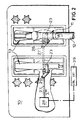
- each nozzle holder includes a frame 20 against which the handle portion 21 of a nozzle 11 engages.
- a crank 26 is also secured to the shaft 22, within the interior of the pump. That crank 26 is connected by a tie-rod 27 to an electro-magnetic actuator 28. When appropriately energised, the actuator 28 moves the tie-rod 27 in the direction A marked on Figure 2, so turning the shaft 22 through about 90°. From the position shown in Figure 2, the rotation of the shaft is clockwise, so moving the arm 23 free of the nozzle in the holder.
- the pair of side by side nozzle holders each has a nozzle locking arrangement including a shaft 22 and an arm 23 as described above, the two cranks 26 being linked together by the same tie-rod 27, whereby both arms 23 are moved into and out of engagement with an associated nozzle, essentially simultaneously.
- a similar arrangement is provided on the opposite side of the pump, whereby operation of the two actuators simultaneously locks or releases all four nozzles.
- the actuators 28 may be operated by a remote switch arrangement 29, which may for example be located in a pay-booth or cashiers area. Equally, all other pumps on a forecourt may similarly be provided with a locking arrangement and the actuators thereof all operated essentially simultaneously.
- a nozzle sensor (not shown) may be provided, in order to detect the presence of a nozzle, properly position within its holder. Such a nozzle detector may be coupled back to the control system, whereby operation of the associated actuator is inhibited in tne event that no nozzle is detected as being present in any given holder. Moreover, a further detector for arm movement to its locking position may be provided, whereby an alarm signal may be generated in the event that a control signal has been provided to an actuator to cause movement of the associated arm to its locked position, and yet no signal is returned within some pre-determined period of time, indicating that the arm has so moved. This will enable an operator to check proper placement of a nozzle in its holder and then take such appropriate remedial action as may be necessary. In the event that there has been a failure in the system, such as non-operation of the actuator 28, then the operator may still lock the nozzle in position using a padlock in the conventional way.
Landscapes
- Engineering & Computer Science (AREA)
- Mechanical Engineering (AREA)
- Loading And Unloading Of Fuel Tanks Or Ships (AREA)
Claims (14)
- Tankstellen-Kraftstoffzapfsäule (10), mit einem flexiblen Zuleitungsschlauch (12), der an seinem freien Ende eine Zapfpistole (11) aufweist, und einer Halterung (13) für die Zapfpistole, wobei die Zapfsäule (10) außerdem ein Befestigungsbauteil (23) aufweist, das an der Zapfsäule montiert ist und zwischen einer Befestigungsposition, in der das Befestigungsbauteil (23) mit der Zapfpistole (11) eingreift, wenn sich diese in ihrer Halterung (13) befindet, und verhindert, daß die Zapfpistole daraus herausgenommen werden kann, und einer Freigabeposition verlagerbar ist, in der die Zapfpistole bezüglich des Befestigungsbauteils freigegeben ist, gekennzeichnet durch ein kraftbetätigtes Betätigungsmittel (28), um das Befestigungsbauteil (23) zwischen seinen beiden Positionen zu verlagern, und eine Steuerungseinrichtung (29) für das kraftbetätigte Betätigungsmittel (28).
- Tankstellen-Kraftstoffzapfsäule nach Anspruch 1, bei der die Steuerungseinrichtung eine Schaltereinrichtung (29) enthält, um das Betätigungsmittel (28) zu steuern, wobei die Schaltereinrichtung bezüglich der Kraftstoffzapfsäule (10) räumlich getrennt angeordnet ist.
- Tankstellen-Kraftstoffzapfsäule nach Anspruch 1 oder 2, bei der die Steuerungseinrichtung (29) den Betrieb des Betätigungsmittels (28) auf elektrischer, pneumatischer oder hydraulischer Basis steuert.
- Tankstellen-Kraftstoffzapfsäule nach einem der vorhergehenden Ansprüche, bei der das Befestigungsbauteil einen Riegel (28) aufweist, der sich in seiner Befestigungsposition durch eine Aussparung (24) erstreckt, die in der Zapfpistole (11) ausgebildet ist.
- Tankstellen-Kraftstoffzapfsäule nach Anspruch 4, bei der sich das Befestigungsbauteil (23) durch eine Handgriffaussparung (24) der Zapfpistole erstreckt.
- Tankstellen-Kraftstoffzapfsäule nach einem der vorhergehenden Ansprüche, bei der das Befestigungsbauteil die Form von einem Arm (23) hat, der für eine Drehbewegung zwischen der Freigabe- und der Befestigungsposition montiert ist.
- Tankstellen-Kraftstoffzapfsäule nach einem der vorhergehenden Ansprüche, bei der das Betätigungsmittel (28) einer Bewegung des Befestigungsbauteils (23) widersteht, die eine andere ist, als wenn durch das Betätigungsmittel betätigt.
- Tankstellen-Kraftstoffzapfsäule nach einem der vorhergehenden Ansprüche, bei der das Betätigungsmittel ein lineares, elektromagnetisches Betätigungsmittel (28) umfaßt, das mit dem Befestigungsbauteil (23) gekoppelt ist.
- Tankstellen-Kraftstoffzapfsäule nach einem der Ansprüche 1 bis 7, bei der das Betätigungsmittel (28) einen Motor mit einem rotierenden Ausgang und einen Schraubgewindeantriebsmechanismus aufweist, durch den die Motorausgangswelle mit dem Befestigungsbauteil (23) gekoppelt ist.
- Tankstellen-Kraftstoffzapfsäule nach einem der vorhergehenden Ansprüche, mit mehr als einem Zuleitungsschlauch (12), wobei jeder Zuleitungsschlauch (12) eine Zapfpistole (11) und eine zugehörige Halterung (14) dafür hat, wobei ein jeweiliges Befestigungsbauteil (23) mit jeder der Halterungen in Beziehung steht und alle Befestigungsbauteile durch das Betätigungsmittel (28) betätigbar sind.
- Tankstellen-Kraftstoffzapfsäule nach einem der vorhergehenden Ansprüche, bei der die Zapfpistolen-Halterung (13) einen Detektor für das Vorhandensein einer Zapfpistole (11) darin, und Einrichtungen aufweist, um den Betrieb des Betätigungsmittels (28) zu verhindern, bis erfaßt wird, daß sich eine Zapfpistole in der Halterung befindet.
- Tankstellen-Kraftstoffzapfsäule nach einem der vorhergehenden Ansprüche, bei der die Steuerungseinrichtung (29) dazu ausgestaltet ist, um nach Betätigung der Steuerungseinrichtung die Verlagerung des Befestigungsbauteils (23) in seine Befestigungsposition zu erfassen, um den Betrieb des Betätigungsmittels (28) zu veranlassen, um eine solche Verlagerung zu bewirken.
- Tankstellenanordnung, mit einer Vielzahl von Kraftstoffzapfsäulen (10) nach einem der vorhergehenden Ansprüche, bei der die Steuerungseinrichtung (29) eine Schalteranordnung enthält, um im wesentlichen einen gleichzeitigen Betrieb der kraftbetätigten Betätigungsmittel (28) von allen Kraftstoffzapfsäulen zu bewirken, um alle Befestigungsbauteile (23) der Zapfsäulen entweder in ihre Freigabeposition oder in ihre Befestigungsposition zu verlagern.
- Tankstellenanordnung nach Anspruch 13, bei der die Schalteranordnung (29) im Kassenbereich der Tankstelle angeordnet ist, die von den Zapfsäulen (10) räumlich getrennt ist.
Applications Claiming Priority (3)
| Application Number | Priority Date | Filing Date | Title |
|---|---|---|---|
| GB9503186 | 1995-02-18 | ||
| GBGB9503186.0A GB9503186D0 (en) | 1995-02-18 | 1995-02-18 | Locking forecourt fuel pump |
| PCT/GB1996/000369 WO1996026155A1 (en) | 1995-02-18 | 1996-02-16 | Locking forecourt fuel pump |
Publications (2)
| Publication Number | Publication Date |
|---|---|
| EP0809601A1 EP0809601A1 (de) | 1997-12-03 |
| EP0809601B1 true EP0809601B1 (de) | 2000-01-19 |
Family
ID=10769811
Family Applications (1)
| Application Number | Title | Priority Date | Filing Date |
|---|---|---|---|
| EP96903101A Expired - Lifetime EP0809601B1 (de) | 1995-02-18 | 1996-02-16 | Verriegelungsvorrichtung für die pumpe in einer kraftstoffabgabe-station |
Country Status (7)
| Country | Link |
|---|---|
| US (1) | US5918766A (de) |
| EP (1) | EP0809601B1 (de) |
| JP (1) | JPH11503391A (de) |
| AU (1) | AU715035B2 (de) |
| DE (1) | DE69606282T2 (de) |
| GB (1) | GB9503186D0 (de) |
| WO (1) | WO1996026155A1 (de) |
Families Citing this family (9)
| Publication number | Priority date | Publication date | Assignee | Title |
|---|---|---|---|---|
| ES2160441B1 (es) * | 1998-02-16 | 2002-05-16 | Gonzalez Jose Luis Palacios | Instalacion de seguridad para carga/desacarga de gases fluidos y torre de consigna correspondiente. |
| US6173865B1 (en) * | 1999-10-13 | 2001-01-16 | Tokheim Corporation | Telescoping fuel dispenser |
| US6648178B2 (en) * | 2001-11-28 | 2003-11-18 | Jeffrey Grunewald | Tap lock apparatus and methods of operation thereof |
| US6962177B1 (en) | 2004-07-27 | 2005-11-08 | Mccommons James A | Locking fuel pump dispenser |
| US20090111072A1 (en) * | 2007-10-30 | 2009-04-30 | Alan Lombardo | Dental implant and abutment mating system |
| IN2012DN03287A (de) | 2009-10-16 | 2015-10-23 | Dresser Wayne Ab | |
| US8844587B1 (en) | 2013-11-01 | 2014-09-30 | James A. McCommons | Locking fuel pump dispenser |
| JP6767191B2 (ja) * | 2016-07-29 | 2020-10-14 | 新明和工業株式会社 | 給油ノズル格納装置及びそれを備えたタンクローリ |
| JP6725390B2 (ja) * | 2016-09-30 | 2020-07-15 | トキコシステムソリューションズ株式会社 | 燃料供給システム |
Family Cites Families (14)
| Publication number | Priority date | Publication date | Assignee | Title |
|---|---|---|---|---|
| US2070560A (en) * | 1931-07-23 | 1937-02-16 | Nat Pumps Corp | Liquid dispensing apparatus |
| US2665032A (en) * | 1950-02-18 | 1954-01-05 | Ossian Engineering Co Inc | Nozzle support and switch operator |
| US2668680A (en) * | 1951-05-19 | 1954-02-09 | Wayne Pump Co | Nozzle lock |
| DE1182978B (de) * | 1963-05-30 | 1964-12-03 | Geraetebau G M B H & Co K G De | Schalteinrichtung an Zapfsaeulen |
| US3178057A (en) * | 1964-03-11 | 1965-04-13 | John Wood Company | Pump operating mechanism |
| US3510630A (en) * | 1966-03-11 | 1970-05-05 | Veeder Industries Inc | Accounting system for fuel dispensing equipment |
| US3705400A (en) * | 1970-12-24 | 1972-12-05 | Warner Swasey Co | Error-compensated position determining |
| US3774227A (en) * | 1971-05-20 | 1973-11-20 | Veeder Industries Inc | Multiple-key lock mechanism |
| US4186850A (en) * | 1978-05-01 | 1980-02-05 | Mahar & Parsons | Gasoline pump assembly and lock arrangement especially suitable for use therewith |
| US4248335A (en) * | 1979-01-25 | 1981-02-03 | Mcquay-Perfex Inc. | Key-operated actuator |
| US4367827A (en) * | 1980-12-08 | 1983-01-11 | Atlantic Richfield Company | Antitheft mechanism for gasoline pump |
| US5038061A (en) * | 1990-05-25 | 1991-08-06 | Olsen John H | Linear actuator/motor |
| US5110010A (en) * | 1990-09-21 | 1992-05-05 | Gilbarco, Inc. | Automatic fuel dispenser actuator |
| US5417805A (en) * | 1993-03-09 | 1995-05-23 | Rosenblad; Axel E. | Brushed film evaporator |
-
1995
- 1995-02-18 GB GBGB9503186.0A patent/GB9503186D0/en active Pending
-
1996
- 1996-02-16 DE DE69606282T patent/DE69606282T2/de not_active Expired - Fee Related
- 1996-02-16 EP EP96903101A patent/EP0809601B1/de not_active Expired - Lifetime
- 1996-02-16 JP JP8525482A patent/JPH11503391A/ja not_active Ceased
- 1996-02-16 AU AU47252/96A patent/AU715035B2/en not_active Ceased
- 1996-02-16 US US08/894,176 patent/US5918766A/en not_active Expired - Lifetime
- 1996-02-16 WO PCT/GB1996/000369 patent/WO1996026155A1/en not_active Ceased
Also Published As
| Publication number | Publication date |
|---|---|
| AU4725296A (en) | 1996-09-11 |
| AU715035B2 (en) | 2000-01-13 |
| DE69606282T2 (de) | 2000-08-31 |
| GB9503186D0 (en) | 1995-04-05 |
| JPH11503391A (ja) | 1999-03-26 |
| US5918766A (en) | 1999-07-06 |
| EP0809601A1 (de) | 1997-12-03 |
| WO1996026155A1 (en) | 1996-08-29 |
| DE69606282D1 (de) | 2000-02-24 |
Similar Documents
| Publication | Publication Date | Title |
|---|---|---|
| EP0809601B1 (de) | Verriegelungsvorrichtung für die pumpe in einer kraftstoffabgabe-station | |
| DE69814924T2 (de) | Sicherheitssystem | |
| US7628182B2 (en) | Modular multi-port manifold and fuel delivery system | |
| EP1525874A2 (de) | Ruckbeständiges Schubladenbetätigungssystem | |
| US5683021A (en) | Locked gun case for vehicle | |
| US8640742B2 (en) | Dispensing apparatus | |
| EP0418744A2 (de) | Verfahren und Vorrichtung zum automatischen Betanken von Kraftfahrzeugen | |
| US4367827A (en) | Antitheft mechanism for gasoline pump | |
| US4440252A (en) | Truck cab hydraulic tilting mechanism | |
| US6962177B1 (en) | Locking fuel pump dispenser | |
| WO2015065566A1 (en) | Locking fuel pump dispenser | |
| JP3433775B2 (ja) | 給油装置 | |
| GB2264271A (en) | Safety system for a liquefied gas bulk tanker vehicle. | |
| CN1082489C (zh) | 预调液分配测量器 | |
| DE102005002245A1 (de) | Verfahren und Vorrichtung zum Betanken eines Fahrzeugs | |
| EP1526484A2 (de) | Verkaufsautomat mit einer Fernbedienung für Klappeschloss | |
| NL1027186C2 (nl) | Hydraulische pompeenheid voor een hydraulische cabinekantelinrichting. | |
| JP3765638B2 (ja) | 給油システム | |
| JP7057166B2 (ja) | 燃料供給装置 | |
| JPH1149299A (ja) | 給油所管理システム | |
| US4097724A (en) | Fuel vending apparatus and method | |
| JP2971559B2 (ja) | 出荷システム | |
| EP0267803B1 (de) | Tanker zum Transport von Flüssigkeit | |
| DE4202075A1 (de) | Vorrichtung zum betanken eines kraftfahrzeuges | |
| JPH08164784A (ja) | 燃料給油車のホースリール制御装置 |
Legal Events
| Date | Code | Title | Description |
|---|---|---|---|
| PUAI | Public reference made under article 153(3) epc to a published international application that has entered the european phase |
Free format text: ORIGINAL CODE: 0009012 |
|
| 17P | Request for examination filed |
Effective date: 19970909 |
|
| AK | Designated contracting states |
Kind code of ref document: A1 Designated state(s): DE FR GB IT |
|
| 17Q | First examination report despatched |
Effective date: 19980205 |
|
| GRAG | Despatch of communication of intention to grant |
Free format text: ORIGINAL CODE: EPIDOS AGRA |
|
| GRAG | Despatch of communication of intention to grant |
Free format text: ORIGINAL CODE: EPIDOS AGRA |
|
| GRAH | Despatch of communication of intention to grant a patent |
Free format text: ORIGINAL CODE: EPIDOS IGRA |
|
| GRAH | Despatch of communication of intention to grant a patent |
Free format text: ORIGINAL CODE: EPIDOS IGRA |
|
| GRAA | (expected) grant |
Free format text: ORIGINAL CODE: 0009210 |
|
| AK | Designated contracting states |
Kind code of ref document: B1 Designated state(s): DE FR GB IT |
|
| REF | Corresponds to: |
Ref document number: 69606282 Country of ref document: DE Date of ref document: 20000224 |
|
| ITF | It: translation for a ep patent filed | ||
| ET | Fr: translation filed | ||
| PLBE | No opposition filed within time limit |
Free format text: ORIGINAL CODE: 0009261 |
|
| STAA | Information on the status of an ep patent application or granted ep patent |
Free format text: STATUS: NO OPPOSITION FILED WITHIN TIME LIMIT |
|
| 26N | No opposition filed | ||
| REG | Reference to a national code |
Ref country code: GB Ref legal event code: IF02 |
|
| PGFP | Annual fee paid to national office [announced via postgrant information from national office to epo] |
Ref country code: IT Payment date: 20080212 Year of fee payment: 13 |
|
| PGFP | Annual fee paid to national office [announced via postgrant information from national office to epo] |
Ref country code: DE Payment date: 20090213 Year of fee payment: 14 |
|
| PGFP | Annual fee paid to national office [announced via postgrant information from national office to epo] |
Ref country code: GB Payment date: 20090302 Year of fee payment: 14 |
|
| PGFP | Annual fee paid to national office [announced via postgrant information from national office to epo] |
Ref country code: FR Payment date: 20090227 Year of fee payment: 14 |
|
| GBPC | Gb: european patent ceased through non-payment of renewal fee |
Effective date: 20100216 |
|
| REG | Reference to a national code |
Ref country code: FR Ref legal event code: ST Effective date: 20101029 |
|
| PG25 | Lapsed in a contracting state [announced via postgrant information from national office to epo] |
Ref country code: FR Free format text: LAPSE BECAUSE OF NON-PAYMENT OF DUE FEES Effective date: 20100301 |
|
| PG25 | Lapsed in a contracting state [announced via postgrant information from national office to epo] |
Ref country code: DE Free format text: LAPSE BECAUSE OF NON-PAYMENT OF DUE FEES Effective date: 20100901 |
|
| PG25 | Lapsed in a contracting state [announced via postgrant information from national office to epo] |
Ref country code: IT Free format text: LAPSE BECAUSE OF NON-PAYMENT OF DUE FEES Effective date: 20090216 Ref country code: GB Free format text: LAPSE BECAUSE OF NON-PAYMENT OF DUE FEES Effective date: 20100216 |