EP0809753B1 - Moteur a combustion interne a injection directe du carburant - Google Patents
Moteur a combustion interne a injection directe du carburant Download PDFInfo
- Publication number
- EP0809753B1 EP0809753B1 EP96901660A EP96901660A EP0809753B1 EP 0809753 B1 EP0809753 B1 EP 0809753B1 EP 96901660 A EP96901660 A EP 96901660A EP 96901660 A EP96901660 A EP 96901660A EP 0809753 B1 EP0809753 B1 EP 0809753B1
- Authority
- EP
- European Patent Office
- Prior art keywords
- combustion chamber
- fuel
- air
- engine
- injection
- Prior art date
- Legal status (The legal status is an assumption and is not a legal conclusion. Google has not performed a legal analysis and makes no representation as to the accuracy of the status listed.)
- Expired - Lifetime
Links
- 238000002485 combustion reaction Methods 0.000 title claims description 333
- 239000000446 fuel Substances 0.000 title claims description 197
- 239000007789 gas Substances 0.000 claims description 92
- 238000002347 injection Methods 0.000 claims description 76
- 239000007924 injection Substances 0.000 claims description 76
- 239000000203 mixture Substances 0.000 claims description 47
- 239000007921 spray Substances 0.000 claims description 32
- 238000000034 method Methods 0.000 claims description 25
- 238000010926 purge Methods 0.000 claims description 25
- 239000000126 substance Substances 0.000 claims description 11
- 238000004891 communication Methods 0.000 claims description 8
- 230000033001 locomotion Effects 0.000 claims description 6
- 230000001419 dependent effect Effects 0.000 claims 5
- 239000012530 fluid Substances 0.000 description 7
- 239000001257 hydrogen Substances 0.000 description 7
- 229910052739 hydrogen Inorganic materials 0.000 description 7
- 230000015572 biosynthetic process Effects 0.000 description 6
- 230000000149 penetrating effect Effects 0.000 description 6
- UFHFLCQGNIYNRP-UHFFFAOYSA-N Hydrogen Chemical compound [H][H] UFHFLCQGNIYNRP-UHFFFAOYSA-N 0.000 description 5
- 238000010276 construction Methods 0.000 description 5
- 239000000567 combustion gas Substances 0.000 description 4
- 230000001965 increasing effect Effects 0.000 description 4
- 238000011144 upstream manufacturing Methods 0.000 description 4
- 230000008901 benefit Effects 0.000 description 3
- 239000006185 dispersion Substances 0.000 description 3
- 238000009826 distribution Methods 0.000 description 3
- 238000007726 management method Methods 0.000 description 3
- 230000004044 response Effects 0.000 description 3
- 230000009471 action Effects 0.000 description 2
- 239000000356 contaminant Substances 0.000 description 2
- 230000002708 enhancing effect Effects 0.000 description 2
- 150000002431 hydrogen Chemical class 0.000 description 2
- 238000012986 modification Methods 0.000 description 2
- 230000004048 modification Effects 0.000 description 2
- 230000004913 activation Effects 0.000 description 1
- QVGXLLKOCUKJST-UHFFFAOYSA-N atomic oxygen Chemical compound [O] QVGXLLKOCUKJST-UHFFFAOYSA-N 0.000 description 1
- 238000000889 atomisation Methods 0.000 description 1
- 230000009286 beneficial effect Effects 0.000 description 1
- 230000000740 bleeding effect Effects 0.000 description 1
- 230000000295 complement effect Effects 0.000 description 1
- 239000004020 conductor Substances 0.000 description 1
- 230000000694 effects Effects 0.000 description 1
- 230000002349 favourable effect Effects 0.000 description 1
- 230000006872 improvement Effects 0.000 description 1
- 230000000977 initiatory effect Effects 0.000 description 1
- 230000003993 interaction Effects 0.000 description 1
- 230000002452 interceptive effect Effects 0.000 description 1
- 238000004519 manufacturing process Methods 0.000 description 1
- 239000000463 material Substances 0.000 description 1
- 239000002184 metal Substances 0.000 description 1
- 239000001301 oxygen Substances 0.000 description 1
- 229910052760 oxygen Inorganic materials 0.000 description 1
- 230000035515 penetration Effects 0.000 description 1
- 230000008569 process Effects 0.000 description 1
- 230000009467 reduction Effects 0.000 description 1
- 238000009420 retrofitting Methods 0.000 description 1
- 230000000630 rising effect Effects 0.000 description 1
- 238000010998 test method Methods 0.000 description 1
- 238000012546 transfer Methods 0.000 description 1
Images


Classifications
-
- F—MECHANICAL ENGINEERING; LIGHTING; HEATING; WEAPONS; BLASTING
- F02—COMBUSTION ENGINES; HOT-GAS OR COMBUSTION-PRODUCT ENGINE PLANTS
- F02B—INTERNAL-COMBUSTION PISTON ENGINES; COMBUSTION ENGINES IN GENERAL
- F02B19/00—Engines characterised by precombustion chambers
- F02B19/12—Engines characterised by precombustion chambers with positive ignition
-
- F—MECHANICAL ENGINEERING; LIGHTING; HEATING; WEAPONS; BLASTING
- F02—COMBUSTION ENGINES; HOT-GAS OR COMBUSTION-PRODUCT ENGINE PLANTS
- F02B—INTERNAL-COMBUSTION PISTON ENGINES; COMBUSTION ENGINES IN GENERAL
- F02B19/00—Engines characterised by precombustion chambers
- F02B19/10—Engines characterised by precombustion chambers with fuel introduced partly into pre-combustion chamber, and partly into cylinder
- F02B19/1004—Engines characterised by precombustion chambers with fuel introduced partly into pre-combustion chamber, and partly into cylinder details of combustion chamber, e.g. mounting arrangements
- F02B19/1014—Engines characterised by precombustion chambers with fuel introduced partly into pre-combustion chamber, and partly into cylinder details of combustion chamber, e.g. mounting arrangements design parameters, e.g. volume, torch passage cross sectional area, length, orientation, or the like
-
- F—MECHANICAL ENGINEERING; LIGHTING; HEATING; WEAPONS; BLASTING
- F02—COMBUSTION ENGINES; HOT-GAS OR COMBUSTION-PRODUCT ENGINE PLANTS
- F02D—CONTROLLING COMBUSTION ENGINES
- F02D41/00—Electrical control of supply of combustible mixture or its constituents
- F02D41/30—Controlling fuel injection
- F02D41/38—Controlling fuel injection of the high pressure type
-
- Y—GENERAL TAGGING OF NEW TECHNOLOGICAL DEVELOPMENTS; GENERAL TAGGING OF CROSS-SECTIONAL TECHNOLOGIES SPANNING OVER SEVERAL SECTIONS OF THE IPC; TECHNICAL SUBJECTS COVERED BY FORMER USPC CROSS-REFERENCE ART COLLECTIONS [XRACs] AND DIGESTS
- Y02—TECHNOLOGIES OR APPLICATIONS FOR MITIGATION OR ADAPTATION AGAINST CLIMATE CHANGE
- Y02T—CLIMATE CHANGE MITIGATION TECHNOLOGIES RELATED TO TRANSPORTATION
- Y02T10/00—Road transport of goods or passengers
- Y02T10/10—Internal combustion engine [ICE] based vehicles
- Y02T10/12—Improving ICE efficiencies
Definitions
- This invention relates to the combustion process of an internal combustion engine and particularly to the enhancement of that process to reduce the level of exhaust emissions, improve the fuel consumption and/or improve combustion stability and/or otherwise enhance the combustion process. More particularly, the invention relates to internal combustion engines wherein fuel is directly injected into the cylinders of the engine.
- the distribution of fuel within the air charge in the engine combustion chamber is preferably of a stratified nature in order to provide improved fuel consumption.
- the creation of such a stratified fuel distribution is particularly difficult to achieve where the fuel is introduced into the air charge prior to the air charge entering the combustion chamber. This is particularly so as the fuel must be delivered into the air charge at a specific time related to the engine cycle which will ensure that all of the fuel reaches the combustion chamber before the inlet port associated therewith is closed.
- the fuel there is a substantial time interval for the fuel to disperse in the air charge, both in the air intake system and in the combustion chamber, before and after closing of the inlet port, and prior to ignition of the air/fuel mixture.
- Hydrogen is typically a preferred enhancing substance to be used in this procedure, but, due to its high rate of dispersion, (approximately 10 times faster than oxygen), relatively large quantities of hydrogen are usually required, particularly where the fuel and hydrogen are introduced into the air charge prior to the delivery thereof to the combustion chamber. Also, as it is desirable for practical reasons to produce the hydrogen within the vehicle rather than merely to supply a reservoir of pre-produced hydrogen, the resulting large consumption of hydrogen necessitates a substantial "on-board" hydrogen generating capacity which consumes energy, occupies space in, and adds weight to the vehicle.
- the physical controls include pockets or cavities formed in a cylinder head at a location relative to the incoming fuel charge to trap therein a readily ignitable fuel/air mixture. Such pockets or cavities can be in the form of pre-combustion chambers having an igniter device such as a spark plug positioned therein.
- the difficulties may arise from the general lack of quiescence within the combustion chamber due to the tumbling or swirling motion of the air or air/fuel mixture prior to ignition.
- the movement of combustion gases within the combustion chamber after ignition adds to the difficulty in creating a readily ignitable air/fuel mixture at the spark plug.
- residual gases and contaminants from the previous combustion event within the cylinder cause difficulties as such gases and contaminants are difficult to scavenge or purge from known pre-combustion chambers.
- an internal combustion engine having a combustion chamber, a pre-combustion chamber communicating with the combustion chamber, injection means located and arranged to periodically inject controlled amounts of fuel into said pre-combustion chamber in a manner and orientation to direct a fuel spray to pass through the pre-combustion chamber into the combustion chamber, and ignition means positioned relative to the pre-combustion chamber and operably arranged to ignite the fuel spray, characterised in that the injection means (70; 101) are so arranged that controlled amounts of fuel and air are periodically injected into said pre-combustion chamber.
- the engine is of reciprocating type and further includes a cylinder with a cylinder head and a piston defining the combustion chamber.
- the pre-combustion chamber is preferably formed in the cylinder head.
- the invention is equally applicable to rotary engines having no cylinders.
- the injection means is arranged and controlled to deliver a metered quantity of fuel whilst also delivering a quantity of air, not necessarily directly related to the quantity of fuel delivered, each cycle.
- the period of delivery of air is continued after completion of the delivery of the fuel to assist in the conveying of fuel on a path to pass the ignition means, and may commence prior to, during and/or after the delivery of the fuel.
- the pre-combustion chamber is alternatively configured to act as a holding chamber for the ignition means.
- separate fuel and air injectors may deliver directly into the pre-combustion chamber and the control of the timing of the delivery thereof may determine the nature of the fuel spray entering the main combustion chamber.
- the period of delivery is of a duration and/or timing to purge the pre-combustion chamber such that an ignitable range of air/fuel ratio is established within the vicinity of the ignition means at the time of ignition.
- the period of delivery is of a duration and/or timing to purge the pre-combustion chamber substantially completely free of fuel and other materials, after each fuel delivery.
- This purging is in respect of unburnt fuel from the previous cycle, residual combustion gases from the previous combustion event, and the normal air charge for the current cycle which may include recycled or residual exhaust gas.
- This purging of the pre-combustion chamber following each fuel delivery serves to create a desirable level of quiescence within the pre-combustion chamber and, in particular, at or adjacent the ignition means. Together with a desired air/fuel ratio at the ignition means - which is typically a lean mixture in the trailing portion of the fuel spray - this purging of the pre-combustion chamber contributes to the creation of a reliable and reproducible condition or environment for ignition. Accordingly, the purging contributes substantially to the effective combustion of the fuel and a resultant reduction in the level of emissions.
- the combustion chamber may be placed in communication with the pre-combustion chamber through a gas conduction means extending from the combustion chamber to the vicinity of the ignition means.
- the gas conduction means may take any desired form but it may be found convenient to employ a narrow bore conduit extending between the combustion chamber and the pre-combustion chamber.
- the conduit provides air to the vicinity of the ignition means.
- the gas conduction means may assist in the formation of a leaner air/fuel mixture during the trailing portion of the fuel spray as this is formed, as a rule, as the piston rises in an engine cylinder causing a flow of gas through the gas conduction means toward toward the ignition means. A consequence is the formation of a leaner air/fuel mixture in the vicinity of the ignition means.
- the gas conduction means may be made selectively communicable to provide controlled communication between the combustion and pre-combustion chambers by a valve means or like device which only allows gas flow therethrough at desired times during an operating cycle of the engine.
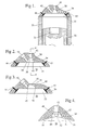
- the pre-combustion chamber is located in the apex region of a cylinder head cavity of wedge shape forming an upper portion of the combustion chamber.
- a cylinder head cavity of wedge shape forming an upper portion of the combustion chamber.
- Such a configuration is commonly referred to as a "pent-roofed" combustion chamber and has been used in four valve per cylinder four-stroke cycle engines.
- the invention is equally applicable to other cylinder head designs.
- the pre-combustion chamber is located substantially centrally of the longitudinal extent of the wedge and is conveniently of a generally circular cross-section with the injection means penetrating the wall thereof in the vicinity of the junction of the wall of the pre-combustion chamber and the wall of the combustion chamber.
- the injection means may be arranged in the uppermost portion of the pre-combustion chamber such that it is located centrally with respect to the vertical motion of the piston.
- the pre-combustion chamber is of a configuration having a narrowed portion, duct, or throat of reduced cross-section, providing the communication between the pre-combustion chamber and the normal combustion chamber.
- the ignition means is conveniently located to establish initial ignition of the fuel within the duct, neck or upstream thereof.
- the ignition means is located centrally in the pre-combustion chamber.
- the pre-combustion chamber is provided by an insert to the cylinder head which communicates with the combustion chamber at one lower end thereof.
- the insert preferably has a narrow duct or neck at a lower end communicating with the combustion chamber. The upper end of the insert conveniently communicates with the injection means.
- the gas conduction means is separate from this narrow duct and may be a passage, conduit, tube or like means also, optionally, forming part of the insert.
- the separate nature of the gas conduction means from the narrow duct allows the generation of a circulation of gas, at relatively high flow through the gas conduction means, advantageously of smaller flow area than the flow area of the narrow duct that promotes rapid travel of a flame front through the narrow duct into the body of the combustion chamber.
- the pre-combustion chamber is formed as part of the injection means and advantageously communicates with the combustion chamber via a narrow duct.
- the narrow duct serves to shield the pre-combustion chamber from the typically turbulent environment within the combustion chamber and further serves to create a narrow penetrating stream of fuel into the combustion chamber.
- the engine may operate on a four stroke cycle such that at least one inlet and at least one outlet valve are provided on opposing sides of the pre-combustion chamber within the cylinder head.
- This arrangement serves to shield the ignition means from the air which enters the combustion chamber via the inlet valve and contributes to the creation of a reproducible ignition environment at or adjacent the ignition means.
- This in turn enables other substances to be introduced to the combustion chamber together with the air and/or air/fuel mixture.
- Such substances may include substantial levels of exhaust gas desirable for emission control.
- a method of operation of a internal combustion engine having a combustion chamber, a pre-combustion chamber communicating with the combustion chamber, injection means located and arranged to periodically inject controlled amounts of fuel into said pre-combustion chamber in a manner and orientation to direct a fuel spray to pass through the pre-combustion chamber into the combustion chamber, and ignition means positioned relative to the pre-combustion chamber to ignite the fuel spray, said method being characterised in that controlled amounts of fuel and air are injected into the pre-combustion chamber by the injecting means so that said pre-combustion chamber is substantially purged of the pre-existing contents therein, establishing an ignitable fuel-air mixture in a portion of the fuel spray spaced rearwardly from the leading end thereof.
- the ignitable fuel-air mixture is established in the trailing portion of the fuel spray.
- a flow of gas from the combustion chamber to the pre-combustion chamber may be generated during the trailing portion of the fuel spray.
- gas may be caused to flow through a gas conduction means extending from the combustion chamber to the vicinity of the ignition means. In such a manner, "leaning out" of the mixture prior to ignition may be assisted with benefit in terms of emission control.
- the engine is of reciprocating type having a cylinder head with the cylinder defining, with the piston, the combustion chamber.
- the pre-combustion chamber is preferably formed in the cylinder head.
- rotary engines are also comprehended by the method of the invention.
- the pre-combustion chamber is located in the apex region of a wedge shaped cylinder head cavity forming an upper portion of the combustion chamber.
- the pre-combustion chamber is located substantially centrally of the longitudinal extent of the wedge.
- the pre-combustion chamber is conveniently of a generally circular cross-section with the injection means penetrating the wall thereof in the vicinity of the junction of the wall of the pre-combustion chamber and the wall of the combustion chamber.
- the injection means is preferably of a known type whereby a metered quantity of fuel is delivered into a quantity of compressed air, and is carried by the air into the combustion chamber.
- a typical example of such an injection means is disclosed in the applicant's United States Patent No. 4934329 which is hereby incorporated herein by reference.
- This type of injector or injection means can be operated to adjust the timing of the introduction of the fuel into the compressed air relative to the commencement of the delivery of the compressed air or other gas from the injector. This enables the timing of the delivery of the fuel to the combustion chamber to be varied relative to the commencement of the delivery of the compressed air. This enables the period of fuel or air delivery to be varied in accordance with engine operating conditions in order to obtain the desired purging of the pre-combustion chamber and positioning of the fuel spray relative to the ignition means as required.
- the injection means may be controlled to perform more than one injection event within a single combustion cycle.
- the injection means may be controlled such that, upon a first opening of a nozzle valve of the injection means, the fuel and air delivered into the pre-combustion chamber purges it free of any residual gases and substantially all of the fuel therein.
- Such injection may also enable mixing of fuel and air within the combustion chamber to facilitate formation of a "homogeneous" charge rather than a stratified charge where the former is appropriate. This is primarily achieved by the end portion of the injection event being constituted by air only.
- a second injection event may occur wherein a small quantity of fuel and/or air is injected into the purged pre-combustion chamber to establish a desired air/fuel ratio in the vicinity of the ignition means.
- the pre-combustion chamber is ideally in a quiescent state and a reliable, reproducible ignition environment is created. This is typically achieved by generating a lean ignitable fuel/air mixture at, or in the vicinity of, the ignition means, again being desirably assisted by the additional flow of gas through the gas conduction means from the combustion chamber to the pre-combustion chamber.
- the invention disclosed herein is particularly suitable for application to four stroke cycle internal combustion engines but may also be applied to engines operating on other cycles such as the two stroke cycle.
- the engine cylinder 33 has a head 34 and a piston 32 incorporating a cavity 31 in the crown thereof.
- the under face of the cylinder head 34 has a cavity 35 which, with the piston 32 and upper face portion of the cylinder 33, defines the combustion chamber 36.
- the cavity 35 may be of any desirable configuration, for example, the wedge-shaped or "pent-roofed" combustion chamber arrangement as depicted in, and described with reference to, Figures 3 and 4.
- the cavity 35 is not essential to the present invention and may be omitted if desired.
- a pre-combustion chamber 38 located within the cylinder head 34 is of a generally circular cross-section having an upper domed section 39 and a lower frusto-conical downwardly diverging portion 40 as is more clearly seen in Figure 2.
- Extending upwardly from the domed section 39 is a co-axial bore 41, preferably internally threaded to receive a portion of a two fluid fuel injector of known construction as previously referred to in the applicant's US Patent Application No. 4934329.
- a sloped bore 42 configured to threadably receive a conventional spark plug (not shown).
- the relative arrangement of the bore 41 and spark plug is such that the electrodes between which the spark is created are located in the location immediately upstream of or at the junction of, the combustion chamber 36 and the frusto-conical portion 40 of the pre-combustion chamber 38.
- An inlet valve 44 and an outlet or exhaust valve 45 are located within the cylinder head 34 on opposing sides of the pre-combustion chamber 38.
- the inlet valve 44 is arranged such that it imparts a tumbling action to the air as it enters the combustion chamber 36.
- the arrangement as shown in the cylinder head 34, together with the resulting combustion chamber 36 is equally applicable to two stroke cycle engines.
- the invention is not limited to engines in which air is imparted with a tumbling motion and is equally applicable to other engines including those wherein air is input to the combustion chamber with a swirling motion.
- the inlet valve 44 opens, air enters the combustion chamber 36 with a tumbling action as it is arranged to pass over the uppermost end of the valve 44.
- An injection means located within the bore 41 is actuated and injects a penetrating narrow fuel spray into the pre-combustion chamber 38.
- the penetration and narrowness of the fuel spray may be modified such as to take account of the distance between the cavity 31 and the injection means. This injection event scavenges or purges the pre-combustion chamber 38 of fuel and residual gases from the previous combustion event.
- the injection means is a two-fluid injector as described hereinbefore such that once all the fuel has been injected, air only flows from the injector means into the pre-combustion chamber 38. This serves to create a level of quiescence within the pre-combustion chamber 38 and further purge a majority of the fuel from within the pre-combustion chamber 38. A desirable air/fuel ratio is subsequently generated at the spark plug creating a reproducible, ignitable environment. This environment is created at the plug independent of events occurring in the combustion chamber 36.
- a gas conduction means - as described in greater detail in reference to the embodiments of Figures 8 and 9 - may be included and play an important role by allowing a flow of air or other gases from the combustion chamber 36 to be directed in a controlled manner at the spark plug and assisting in the purging of residual exhaust gas and formation of a lean air/fuel mixture especially at the trailing end of the fuel injection event.
- This environment is created at the spark plug independent of events occurring in the combustion chamber 36.
- formation of the air/fuel mixture within the pre-combustion chamber 38 may be arranged to occur in the compressed gases which enter the pre-combustion chamber 38 after fuel has been purged therefrom but before ignition.
- the combustion chamber 36 may preferably be designed to facilitate the flow of these compressed gases, which mostly comprise air, into the pre-combustion chamber 38 once the initial purging of fuel and gases therefrom has occurred.
- FIGS 3 and 4 depict a modified form of cylinder head which may be used in conjunction with the cylinder 33 and piston 32, as previously referred to in reference to Figures 1 and 2, a "pent-roofed" combustion chamber arrangement, as previously mentioned, is shown.
- FIGs 3 and 4 depict a modified form of cylinder head which may be used in conjunction with the cylinder 33 and piston 32, as previously referred to in reference to Figures 1 and 2, a "pent-roofed" combustion chamber arrangement, as previously mentioned, is shown.
- like parts in Figures 3 and 4 are referenced with the same numbers as used in Figures 1 and 2.
- the pre-combustion chamber 47 shown in Figures 3 and 4, is located at the apex of cavity 35 and has an upper portion 48 of generally truncated or conical cross-section, comprising an upwardly extending co-axial bore 41 to receive a portion of a two fluid fuel injector in a similar manner to that described with respect to Figures 1 and 2.
- the lower portion 49 of the pre-combustion chamber 47 is formed substantially coaxial with the upper portion 48.
- the bore 41 is arranged relative to the sloped bore 42 which is configured to threadably receive a conventional spark plug (not shown) such that the electrodes of the spark plug are located in the location immediately upstream of, or at the junction of, the combustion chamber 36 and the lower portion of the pre-combustion chamber 47.
- the cavity 35 is defined by two upwardly and oppositely inclined surfaces 51 which meet a line 52 and together define a "pent-roofed" combustion chamber 36 which is commonly used on some four stroke cycle engines.
- the disposition of the annular bore 41 to receive the fuel injector and the spark plug bore 42 complement each other and together provide the ability to achieve particularly desirable ignition conditions, particularly with the fuel injector preferably being of the two fluid type which delivers fuel entrained in a gas such as air.
- the pre-combustion chamber 38, 47 can be purged of combustion residue from a previous cycle before the initiation of the combustion of the new air/fuel mixture.
- the actual ignition of the air/fuel mixture can be controlled, particularly in regard to efficiency of ignition of a part of the fuel spray, which is appropriately delivered relative to the ignition means.
- use of an injection means 70 where the fuel is delivered entrained in a charge of air, desirably together with flow of gas from the combustion chamber through the gas conduction means 81 to the spark plug may enable the entry of the fuel into the air charge to be controlled to achieve a desired air/fuel ratio in the vicinity of the ignition means or spark plug at the time of occurrence of the spark discharge.
- the pre-combustion chamber may be asymmetric about a longitudinal axis of symmetry of the combustion chamber 36, as shown in Figure 10.
- the ignition means 74 is enabled to project deeply into the pre-combustion chamber 76 without interfering with delivery of fuel and air from the injector 101 and assisting ignition because the ignition means 74 is located in a zone at which the desirable air/fuel ratio for ignition will exist due to the purging flow of cylinder gases into the pre-combustion chamber 76 from combustion chamber 36 as the piston rises.
- a secondary gas conduction means may be communicated between a compressed gas source and the pre-combustion chamber 76 to deliver a flow of compressed gas thereto.
- the compressed gas source may, without limitation, be a compressed air supply, for example, an air compressor or air compressed circuit. Alternatively, or additionally, the air supply may be that supplying compressed air to the injection means 101, for example an air or air/fuel rail.
- a conduit may form the secondary gas conduction means and may communicate with the compressed gas source at any desired location.
- the conduit or other form of secondary gas conduction means discharges gas in the vicinity of the ignition means 74 to enable more effective control over air/fuel ratio in this region.
- a thin dividing member may be provided to physically isolate the pre-combustion chamber 38, 47 from the cylinder head cavity 35.
- Such a dividing member may be provided with a small orifice or opening suitably located therein such that communication may only occur between the pre-combustion chamber 38 or 47 and combustion chamber 36 through the orifice. It is envisaged that such a dividing member would further shield the pre-combustion chamber 38 or 47 from the turbulence and other activity within the combustion chamber 36. This may contribute further to achieving a level of quiescence in the pre-combustion chamber 38 or 47.
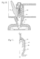
- Figure 5 is a sectional view of an alternative shape of pre-combustion chamber 60 where the delivery passage 61 therefrom is of a restricted flow area to increase the velocity of the fuel/air mixture delivered to the combustion chamber.
- the fuel and air delivered from a two fluid injector unit which may be of the construction disclosed in the applicant's prior U.S. patent, previously referred to herein, enters the pre-combustion chamber 60 at the end 62 and a spark plug is arranged within the passage 63 in the conventional manner.
- the spark plug is positioned so that it will effectively ignite the fuel/air mixture.
- the pre-combustion chamber 60 may be arranged as an insert to a cylinder head of an engine or may in fact be formed as part of an injection means or as an attachment thereto which communicates with the main combustion chamber of the engine cylinders.
- Such an integral unit may then enable retrofitting of the combined injection means and pre-combustion chamber to existing engines. This may be possible using the existing spark plug bore in the cylinder head.
- Figure 6 shows such an arrangement wherein a pre-combustion chamber insert 69, not unlike that shown in Figure 5, is arranged within a corresponding bore in the cylinder head 34.
- An injection means 70 comprising a fuel injector 71 and an air injector 72 is axially arranged within an opening 73 of the pre-combustion chamber insert 69.
- a spark plug 74 is arranged to communicate with a corresponding threaded bore 75 in the insert 69 such that the electrodes thereof lie within the pre-combustion chamber 76 at a lower end thereof.
- the pre-combustion chamber 76 is approximately 0.2-1.0% of the maximum combustion chamber volume and communicates therewith via a narrowed portion, the duct or throat 77.
- the throat is arranged to provide a contained and penetrating fuel spray into the combustion chamber 36.
- the throat 77 is narrow to provide increased velocity to the gases exiting the pre-combustion chamber 76.
- the throat 77 cannot be too narrow or the time taken to purge the pre-combustion chamber 76 will be too long and subsequently affect the satisfactory operation of the engine.
- the cross-sectional area of the throat 77 may be approximately 30-50 % larger than the nozzle opening (not shown) of the injection means 70 which enables communication with the pre-combustion chamber 76.
- the small throat area causes the chamber 76 to fill with fuel and air which substantially scavenges or purges the chamber 76 of any residual gases.
- This fuel/air mixture is subsequently delivered into the main combustion chamber 36 in the form of a narrow penetrating spray which interacts with the cavity 31 in the piston 32 in a known manner (see Figure 7).
- the cavity 31 may be arranged with a specific shape such that it interacts with the fuel spray in the desired manner.
- the axis of the pre-combustion chamber 76, and consequently the axis of the fuel/air spray emitted from the throat 77, is coincident with the axis of the cavity 31 at a convenient piston position.
- the two axes are coincident when the piston is at a position corresponding to 55° BTDC.
- air from the air injector 72 only is delivered by the injection means 70. This serves to further purge substantially all of the fuel from the pre-combustion chamber 76 and create a desirable air/fuel ratio at the spark plug electrodes.
- the pre-combustion chamber 76 is essentially free of any residual gases and is substantially isolated from the main combustion chamber 36 such that a desirable level of quiescence is created therein. This is a reliable and reproducible environment for ignition.
- the air fuel ratio at the spark plug electrodes may be controlled to be different to that present in the main combustion chamber 36. This is essentially possible due to the flexibility of the two fluid injection means 70.
- ignition of the contents of pre-combustion chamber 76 may take place after entry thereto of compressed gases from the combustion chamber 36.
- compressed air from the combustion chamber 36 flows into the pre-combustion chamber 76 as a result of the increase in pressure in combustion chamber 36 caused by the rise of the piston 32 in the cylinder.
- gases being mostly air, serve to further lean out the air/fuel mixture in the pre-combustion chamber 76. Accordingly, it may be desirable to ignite the fuel/air mixture as this air enters the pre-combustion chamber 76 rather than when the final portion of air is delivered by injection means 70.
- the combustion chamber cavity 35 may preferably be arranged to facilitate the flow of combustion gases back into the pre-combustion chamber 76.
- Such a configuration is shown in Figures 6 and 7.
- the air/fuel mixture in the pre-combustion chamber 76 may be stoichiometric while a large proportion of exhaust gas from an EGR system remains in the combustion chamber 36.
- a torch of flame is emitted into the combustion chamber 36, through the throat 77, and into the tumbling air within the combustion chamber 36 which results in rapid combustion of the air/fuel mixture therein.
- the ability to mix/use different substances with the air and fuel such as exhaust gas from a suitable EGR system, such as that disclosed in the applicant's corresponding International patent application No. PCT/AU94/00288, is increased.
- the air/fuel mixture in the chamber 76 may be stoichiometric while a large proportion of exhaust gas from an EGR system remains in the combustion chamber 36.
- combustion possible is essentially faster than that which may be achieved by way of a conventional spark plug in the combustion chamber arrangement and may permit reduced fuel consumption and NO x emissions. Further, this construction allows for air/fuel ratios in the main combustion chamber 36 to be as low as 120:1.
- spark plug 74 and injection means 70 to the pre-combustion chamber 76 are not limited to that shown in Figure 6 and other variants are possible.
- both the spark plug 74 and the nozzle opening of the injection means 70 may be arranged at the uppermost end of the chamber 76 in a side by side relationship.
- the spark plug 74 may be replaced by an ignition means which has electrodes arranged within the insert 69 such that a spark occurs across the throat 77 of the pre-combustion chamber 76.
- the spark plug 74 or electrodes arranged within the insert 69 may be configured to spark onto the end of the injection means 71 itself or onto a projection 78 of the injection means as seen in Figure 7.
- the fuel and air injectors 71 and 72 may be arranged to separately deliver fuel and air into the pre-combustion chamber 76 via separate orifices.
- Such orifices could be arranged at the top of the pre-combustion chamber 76 and the timing of delivery of both the fuel and air would determine the resultant air/fuel ratio and nature of the fuel spray to be delivered through the throat 77.
- a plurality of throats 77, or orifices, may be provided through which fuel may be delivered to the combustion chamber 36.
- the pre-combustion chamber 76 may be provided with a baffle 106, preferably curvilinear to promote a desired spray geometry though a vertical plate.
- the baffle 106 acts as a flow guide for the fuel/air mixture delivered from injector 101 and here the ignition means 74 is located between baffle 106 and the inner wall of pre-combustion chamber 76 in a region 107 defined therebetween which is isolated from the fuel spray from injector 101.
- flow of the air/fuel mixture is directed downward toward the narrowed portion or throat 77 and gases in region 107 outward from the baffle 106 remain fuel-lean as the spray from the injector 101 does not reach this region 107.
- the "leaning-out" of fuel in gases present in region 107 may further be promoted by bleeding of air or other gases from the compressed air or gas source (not shown), for example as described with reference to Figure 10, through a secondary gas conduction means into region 107.
- the secondary gas conduction means may be a conduit which opens into the pre-combustion chamber through a small aperture formed in the wall of pre-combustion chamber 76.
- the conduit may connect with the air or gas supply to the engine.
- the air or gas supply means may be made selectively communicable, under certain engine operating conditions, with region 107, through a valve, orifice or other flow control means. If a valve is employed, this could be solenoid controlled.
- the aperture remains continuously open and is small enough to enable flow of gas into the pre-combustion chamber region 107, preferably in the vicinity of the ignition means to enable more effective control over air/fuel ratio in this region.
- the aperture is small, the quantity of combustion gases which may enter the aperture and thus the conduit or other secondary gas conduction means is insubstantial.
- the timing of the delivery of the air/fuel mixture by the injector to the pre-combustion chamber of each of the embodiments described, and the activation of the spark plug are typically controlled by an electronic control unit (ECU) as is well known in the engine management field.
- the ECU is programmed so that the delivery of the air charge to the pre-combustion chamber and the introduction of the fuel to the air charge are timed so that an ignitable mixture is created at the spark plug when the spark is delivered.
- the timing of the delivery of the spark is preferably such that is does not ignite the leading section of the fuel spray issued during the injection event and preferably ignites the trailing or an outer lean section thereof.
- FIG 8 shows an embodiment similar to Figure 7 described above with the additional feature of a gas conduction means, here taking the form of a conduit 81.
- the conduit 81 extends from the combustion chamber 36 to the spark plug 74 disposed within the pre-combustion chamber 76.
- the use of a light metal, a conductive material allows the formation of a heat transfer path as well as a gas flow path from the combustion chamber 36 to the pre-combustion chamber 76.
- the conduit 81 also forms part of an insert to the cylinder head of the engine though it could equally be formed separately, for example as part of the cylinder block.
- the conduit 81 extends approximately parallel to an axis extending vertically through the centre of the combustion chamber 36 and cylinder head and opens proximate to spark plug 74.
- the conduit 81 may be arranged in any desired manner at an any desired trajectory which facilitates manufacture and achieves the objective of delivering gas to the vicinity of spark plug 74 to achieve a desired lean air/fuel mixture thereat in the trailing portion of the fuel injection event.
- conduit 81 is separate from the throat of the pre-combustion chamber and, advantageously, does not extend therethrough.
- the throat 77 which serves the important function of direction of fuel spray into the combustion chamber 36 is not obstructed by the conduit 81.
- conduit 81 should be less than that of throat 77 to ensure that a high pressure flow of air is created therethrough in response to rise of a piston within the cylinder of which combustion chamber 36 forms part.
- the expansion that follows ignition causes air flow through the throat 77 and a kind of circulation may be established through the pre-combustion chamber 76.
- the pre-combustion chamber 76 is essentially free of any residual gases and is substantially isolated from the main combustion chamber 36 such that a desirable level of quiescence is created therein. This is a reliable and reproducible environment for ignition.
- the air/fuel ratio at the spark plug electrodes may be controlled through control of flow through conduit 81 to be different to that present in the main combustion chamber 36. This is essentially possible due to the flexibility of the two fluid injection means 70.
- conduit 81 is not provided with valve or like means to control flow of gas between combustion chamber 36 and pre-combustion chamber 76, it will be understood that such control could be employed, if desired.
- a solenoid valve could be opened to allow gas flow to pre-combustion 76 in response, for example, to sensed engine position. Opening, or a degree of opening, of the valve or like means might also, or alternatively, be controlled in accordance with engine operating conditions.
- a valve openable in response to pressure in the combustion chamber 36 rising above a predetermined level might be employed instead.
- ignition could follow entry to the pre-combustion chamber 76 of compressed gases from the combustion chamber 36 which have flowed through conduit 81.
- Figure 9 shows a further embodiment similar to that of Figure 6 but including a gas conduit 81.
- the gas conduit 81 may form part of the insert 69.
- the embodiment is the same as that described with respect to Figure 7.
- the spark plug 74 could be formed integral with gas conduit 81 and, if desired, a plurality of gas conduits 81 could be provided though this may be avoided with benefit of a less complex arrangement.
- pre-combustion chamber configuration and location, and fuel ignition management described herein is particularly applicable to four stroke cycle engines but may also be used in relation to other forms of engines including two stroke cycle engines and rotary engines.
Landscapes
- Engineering & Computer Science (AREA)
- Chemical & Material Sciences (AREA)
- Combustion & Propulsion (AREA)
- Mechanical Engineering (AREA)
- General Engineering & Computer Science (AREA)
- Combustion Methods Of Internal-Combustion Engines (AREA)
- Exhaust-Gas Circulating Devices (AREA)
Claims (46)
- Moteur à combustion interne comportant une chambre de combustion (36), une chambre de pré-combustion (38; 47; 60; 76) communiquant avec la chambre de combustion (36), des moyens d'injection (70 ; 101) placés et disposés pour injecter périodiquement des quantités contrôlées de carburant dans ladite chambre de pré-combustion (38 ; 47 ; 60 ; 76) selon une manière et une disposition permettant de diriger le carburant pulvérisé pour assurer son passage dans la chambre de pré-combustion (38 ; 47 ; 60 ; 76) de manière à pénétrer dans la chambre de combustion (36), et des moyens d'allumage (74) positionnés par rapport à la chambre de pré-combustion (38; 47; 60; 76) et disposés de manière opérationnelle pour enflammer le carburant pulvérisé, caractérisé en ce que les moyens d'injection (70; 71) sont disposés de manière à ce que des quantités contrôlées de carburant et d'air soient périodiquement injectées dans ladite chambre de combustion préliminaire.
- Moteur selon la revendication 1, comprenant, en outre, un cylindre (33) avec une tête de cylindre et un piston (32) définissant la chambre de combustion (36) selon lequel ladite chambre de pré-combustion (38 ; 47) est formée dans ladite tête de cylindre (34).
- Moteur selon la revendication 1 ou la revendication 2, selon lequel ledit moyen d'injection (70 ; 101) est disposé et commandé pour injecter une quantité de carburant et une quantité d'air mesurées dans ladite chambre de pré-combustion (38 ; 47 ; 60 ; 76).
- Moteur selon l'une quelconque des revendications précédentes, selon lequel la chambre de combustion (36) et la chambre de pré-combustion (60 ; 76) communiquent via une partie rétrécie (61 ; 77) présentant une section transversale inférieure à celle de la chambre de pré-combustion (60 ; 76).
- Moteur selon l'une quelconque des revendications précédentes, selon lequel ladite chambre de pré-combustion (38 ; 47 ; 76) est une chambre de support pour les moyens d'allumage (74).
- Moteur selon l'une quelconque des revendications précédentes, selon lequel des injecteurs d'air et de carburant séparés (71, 72) sont disposés pour alimenter directement la chambre de pré-combustion (38 ; 47 ; 76).
- Moteur selon l'une quelconque des revendications précédentes, selon lequel ladite chambre de combustion (36) communique avec la chambre de pré-combustion (76) via un moyen de conduction des gaz (81) s'étendant depuis la chambre de combustion jusqu'au voisinage du moyen d'allumage (74).
- Moteur selon la revendication 7, selon lequel ledit moyen de conduction des gaz (81) est prévu pour assurer la communication contrôlée entre ladite chambre de combustion (36) et ladite chambre de pré-combustion (76).
- Moteur selon la revendication 7 ou la revendication 8, lorsqu'il est directement ou indirectement caractérisé par la revendication 4, selon lequel ledit moyen de conduction des gaz (81) est séparé de ladite partie rétrécie (77).
- Moteur selon l'une quelconque des revendications 2 à 9, selon lequel ledit moyen d'injection (70) est placé à l'intérieur de ladite chambre de pré-combustion (38 ; 47 ; 60 ; 76) en une position sensiblement en regard d'une communication entre ladite chambre de combustion (36) et ladite chambre de pré-combustion (38 ; 47 ; 60 ; 76).
- Moteur selon la revendication 2 ou selon l'une quelconque des revendications 3 à 10 lorsqu'il est directement ou indirectement dépendant de la revendication 2, selon lequel ladite chambre de pré-combustion (60) est constituée par un insert (69) dans ladite tête de cylindre, dont une extrémité inférieure communique avec ladite chambre de combustion (36) et une extrémité supérieure communique avec ledit moyen d'injection (70).
- Moteur selon l'une quelconque des revendications précédentes, selon lequel ladite chambre de pré-combustion (76) fait partie dudit moyen d'injection (70).
- Moteur selon l'une quelconque des revendications précédentes, selon lequel la période d'injection d'air se poursuit une fois le carburant injecté.
- Moteur selon l'une quelconque des revendications précédentes, selon lequel la période d'injection présente une durée et/ou une temporisation permettant de purger la chambre de pré-combustion (38 ; 47 ; 60 ; 76).
- Moteur selon la revendication 14, selon lequel ledit moyen d'allumage (74) est prévu pour être protégé contre l'air pénétrant dans ladite chambre de combustion (36) par une soupape d'admission (44).
- Moteur selon l'une quelconque des revendications précédentes, prévu pour qu'une substance autre que l'air et le carburant puisse être introduite dans ladite chambre de pré-combustion (38 ; 47 ; 60 ; 76).
- Moteur selon la revendication 2 ou selon l'une quelconque des revendications 3 à 16, lorsqu'il est directement ou indirectement caractérisé par la revendication 2, selon lequel ledit moyen d'injection (70) est disposé dans la partie supérieure de la chambre de pré-combustion (38 ; 47) dans une position centrale par rapport au déplacement vertical dudit piston (32).
- Moteur selon l'une quelconque des revendications 1 à 3, selon lequel ladite chambre de pré-combustion (38 ; 47 ; 60 ; 76) est physiquement isolée de ladite chambre de combustion (36).
- Moteur selon l'une quelconque des revendications, selon lequel ladite chambre de pré-combustion (38 ; 47 ; 60 ; 76) représente environ 0,2 à 1,0% du volume maximal de la chambre de combustion (36).
- Moteur selon la revendication 4 ou selon l'une quelconque des revendications 5 à 19 lorsqu'il est directement ou indirectement caractérisé par la revendication 4, selon lequel la superficie de la section transversale de ladite partie rétrécie (61 ; 77) est supérieure d'environ 30 à 50% à une ouverture de buse dudit moyen d'injection (70).
- Moteur selon l'une quelconque des revendications précédentes, selon lequel ladite chambre de pré-combustion (76) comprend un moyen formant chicane (106) définissant une zone (107) isolée du carburant pulvérisé à partir dudit moyen d'injection pour faciliter l'allumage à un rapport air/carburant requis dans ladite zone (107).
- Moteur selon la revendication 21, selon lequel une alimentation en air ou en gaz est prévue pour alimenter ladite zone (107) en gaz.
- Moteur selon l'une quelconque des revendications 1 à 22, selon lequel ladite chambre de pré-combustion (76) est asymétrique autour d'un axe longitudinal de ladite chambre de combustion (76).
- Moteur selon l'une quelconque des revendications précédentes, selon lequel un moyen de conduction de gaz secondaire est prévu entre une source de gaz comprimé et la chambre de pré-combustion (38 ; 47 ; 60 ; 76) au voisinage du moyen d'allumage (74).
- Moteur selon la revendication 24, selon lequel ladite source de gaz comprimé est une source d'air comprimé pour alimenter ledit moyen d'injection (70) en air.
- Moteur selon la revendication 24 ou la revendication 25, selon lequel ledit moyen de conduction de gaz secondaire est relié à ladite chambre de pré-combustion (38 ; 47 ; 60 ; 76) par une petite ouverture.
- Moteur selon la revendication 26, selon lequel ladite petite ouverture est continuellement ouverte, assurant une communication continue entre la chambre de pré-combustion (38 ; 47 ; 60 ; 76) et la source de gaz comprimé.
- Procédé de fonctionnement d'un moteur à combustion interne (20) présentant une chambre de combustion (36), une chambre de pré-combustion (38; 47 ; 60; 76) communiquant avec la chambre de combustion (36); des moyens d'injection (70) placés et disposés de manière à injecter périodiquement des quantités contrôlées de carburant dans ladite chambre de pré-combustion (38 ; 47 ; 60 ; 76) selon une manière et une orientation permettant de diriger le carburant pulvérisé pour assurer son passage dans la chambre de pré-combustion (38 ; 47 ; 60 ; 76) de manière à pénétrer dans la chambre de combustion (36), et des moyens d'allumage (74) positionnés par rapport à la chambre de pré-combustion (38 ; 47 ; 60 ; 76) pour enflammer le carburant pulvérisé, ledit procédé étant caractérisé en ce que des quantités contrôlées de carburant et d'air sont injectées dans la chambre de pré-combustion (38 ; 47 ; 60 ; 76) par les moyens d'injection (70) pour purger le contenu pré-existant dans cette dernière, en établissant un mélange carburant-air inflammable, dans une partie du carburant pulvérisé, en arrière de l'extrémité de tête de ce dernier .
- Procédé selon la revendication 28, selon lequel ledit mélange air-carburant inflammable est établie à l'arrière de la partie de carburant pulvérisé.
- Procédé selon la revendication 28 ou la revendication 29, selon lequel un écoulement de gaz provenant de la chambre de combustion (36) et pénétrant dans la chambre de pré-combustion (38 ; 47 ; 60 ; 76) est généré à l'arrière de ladite partie de carburant pulvérisé.
- Procédé selon l'une quelconque des revendications 28 à 30, selon lequel un écoulement de gaz provenant de la chambre de combustion (36) est amené à s'écouler dans un moyen de conduction de gaz (81) jusqu'à la chambre de pré-combustion (76) au voisinage d'un moyen d'allumage (74) placé dans cette dernière.
- Procédé selon l'une quelconque des revendications 28 à 32, selon lequel ledit moyen d'injection (70) est commandé pour injecter une quantité de carburant et une quantité d'air mesurées dans ladite chambre de pré-combustion (38 ; 47 ; 60 ; 76).
- Procédé selon l'une quelconque des revendications 28 à 33, selon lequel l'air et le carburant sont injectés directement dans ladite chambre de pré-combustion (38 ; 47 ; 60 ; 76).
- Procédé selon l'une quelconque des revendications 28 à 33, selon lequel une substance autre que l'air ou le carburant est introduite dans ladite chambre de pré-combustion (38 ; 47 ; 60 ; 76).
- Procédé selon l'une quelconque des revendications 28 à 34, selon lequel la période d'injection de l'air se poursuit une fois le carburant injecté.
- Procédé selon l'une quelconque des revendications 28 à 35, selon lequel la période d'injection présente une durée et/ou une temporisation pour purger la chambre de pré-combustion (38 ; 47 ; 60 ; 76).
- Procédé selon la revendication 36, selon lequel la période d'injection est sélectionnée pour établir une plage requise de rapports du mélange air-carburant au niveau du moyen d'allumage (74) avant l'allumage.
- Procédé selon l'une quelconque des revendications 28 à 37, selon lequel le moyen d'injection (70) est commandé pour effectuer plus d'un événement d'injection en un seul cycle de combustion.
- Procédé selon la revendication 38, selon lequel ledit moyen d'injection (70) est commandé de telle sorte que, lors d'une première ouverture d'un obturateur de buse dudit moyen d'injection (70), un mélange air-carburant est injecté, en un premier événement d'injection, dans ladite chambre de pré-combustion (38 ; 47 ; 60 ; 76) pour purger ladite chambre du carburant et des gaz résiduels.
- Procédé selon la revendication 39, selon lequel l'opération de purge est suivie d'un deuxième événement d'injection selon lequel une quantité de carburant et/ou d'air est injectée dans la chambre de pré-combustion purgée (38 ; 47 ; 60 ; 76) pour établir un rapport requis du mélange air-carburant au voisinage d'un moyen d'allumage (74) placé dans cette dernière.
- Procédé selon la revendication 39 ou la revendication 40, selon lequel une partie d'extrémité dudit premier événement d'injection ou dudit deuxième événement d'injection est constituée par de l'air uniquement.
- Procédé selon la revendication 31 ou selon l'une quelconque des revendications 32 à 41 lorsque le procédé est directement ou indirectement caractérisé par la revendication 31, selon lequel l'écoulement de gaz dans ledit moyen de conduction de gaz (81) entre ladite chambre de combustion (36) et ladite chambre de pré-combustion (76) est contrôlé.
- Procédé selon l'une quelconque des revendications 28 à 42, selon lequel l'inflammation initiale du carburant est effectuée dans une conduite assurant la communication de ladite chambre de combustion (36) avec ladite chambre de pré-combustion (38 ; 47 ; 60 ; 76).
- Procédé selon l'une quelconque des revendications 28 à 43, selon lequel un mélange air-carburant s'enflamme dans une zone (107) d'une chambre de pré-combustion (76) séparée par une chicane (106) d'une partie de ladite chambre de pré-combustion dans laquelle le carburant est amené par ledit moyen d'injection (70).
- Procédé selon la revendication 44, selon lequel de l'air ou du gaz est injecté dans ladite zone (107).
- Procédé selon l'une quelconque des revendications 28 à 45, selon lequel ledit moyen d'allumage (74) est placé dans une chambre de pré-. combustion (38 ; 47 ; 60 ; 76) disposé de manière asymétrique autour d'un axe longitudinal de ladite chambre de pré-combustion et un rapport de mélange air-carburant requis pour l'allumage est obtenu en raison de l'écoulement de gaz de purge dans une partie de la chambre de pré-combustion dans laquelle le moyen d'allumage (74) est placé.
Applications Claiming Priority (4)
| Application Number | Priority Date | Filing Date | Title |
|---|---|---|---|
| AUPN1186A AUPN118695A0 (en) | 1995-02-16 | 1995-02-16 | Improvements relating to internal combustion engines |
| AUPN118695 | 1995-02-16 | ||
| AUPN1186/95 | 1995-02-16 | ||
| PCT/AU1996/000078 WO1996025592A1 (fr) | 1995-02-16 | 1996-02-16 | Moteur a combustion interne a injection directe du carburant |
Publications (3)
| Publication Number | Publication Date |
|---|---|
| EP0809753A1 EP0809753A1 (fr) | 1997-12-03 |
| EP0809753A4 EP0809753A4 (fr) | 1998-12-23 |
| EP0809753B1 true EP0809753B1 (fr) | 2003-06-11 |
Family
ID=3785544
Family Applications (1)
| Application Number | Title | Priority Date | Filing Date |
|---|---|---|---|
| EP96901660A Expired - Lifetime EP0809753B1 (fr) | 1995-02-16 | 1996-02-16 | Moteur a combustion interne a injection directe du carburant |
Country Status (11)
| Country | Link |
|---|---|
| US (1) | US5829407A (fr) |
| EP (1) | EP0809753B1 (fr) |
| JP (1) | JPH11500510A (fr) |
| KR (1) | KR19980702310A (fr) |
| AR (1) | AR000963A1 (fr) |
| AU (1) | AUPN118695A0 (fr) |
| DE (1) | DE69628638T2 (fr) |
| MY (1) | MY132217A (fr) |
| TW (1) | TW339392B (fr) |
| WO (1) | WO1996025592A1 (fr) |
| ZA (1) | ZA961254B (fr) |
Families Citing this family (30)
| Publication number | Priority date | Publication date | Assignee | Title |
|---|---|---|---|---|
| AUPP070497A0 (en) * | 1997-12-03 | 1998-01-08 | Orbital Engine Company (Australia) Proprietary Limited | Improved method of fuelling an engine |
| US6484700B1 (en) | 2000-08-24 | 2002-11-26 | Synerject, Llc | Air assist fuel injectors |
| US6402057B1 (en) | 2000-08-24 | 2002-06-11 | Synerject, Llc | Air assist fuel injectors and method of assembling air assist fuel injectors |
| US6302337B1 (en) | 2000-08-24 | 2001-10-16 | Synerject, Llc | Sealing arrangement for air assist fuel injectors |
| US6561167B2 (en) | 2001-02-16 | 2003-05-13 | Synerject, Llc | Air assist fuel injectors |
| WO2002095202A1 (fr) | 2001-05-23 | 2002-11-28 | Moe Cordell R | Moteur rotatif |
| US6945219B2 (en) * | 2004-02-09 | 2005-09-20 | Bombardier Recreational Products Inc. | Dual zone combustion chamber |
| KR101141705B1 (ko) * | 2005-06-17 | 2012-05-04 | 삼성테크윈 주식회사 | 연소기용 예혼합식 토치점화기 |
| WO2009114327A1 (fr) | 2008-03-12 | 2009-09-17 | Cameron International Corporation | Moteur à combustion interne équipé d’une soupape d’injection voilée et système de chambre de précombustion |
| US8544443B2 (en) * | 2008-03-12 | 2013-10-01 | Cameron International Corporation | Pre-chamber |
| US9476347B2 (en) | 2010-11-23 | 2016-10-25 | Woodward, Inc. | Controlled spark ignited flame kernel flow in fuel-fed prechambers |
| US9172217B2 (en) | 2010-11-23 | 2015-10-27 | Woodward, Inc. | Pre-chamber spark plug with tubular electrode and method of manufacturing same |
| US8584648B2 (en) | 2010-11-23 | 2013-11-19 | Woodward, Inc. | Controlled spark ignited flame kernel flow |
| US9856848B2 (en) | 2013-01-08 | 2018-01-02 | Woodward, Inc. | Quiescent chamber hot gas igniter |
| US9765682B2 (en) | 2013-06-10 | 2017-09-19 | Woodward, Inc. | Multi-chamber igniter |
| JP5920317B2 (ja) * | 2013-11-13 | 2016-05-18 | 株式会社デンソー | 副室式内燃機関 |
| EP3271561B1 (fr) | 2015-03-20 | 2018-12-12 | Woodward, Inc. | Système d'allumage à préchambres parallèles |
| US9653886B2 (en) | 2015-03-20 | 2017-05-16 | Woodward, Inc. | Cap shielded ignition system |
| US9890689B2 (en) * | 2015-10-29 | 2018-02-13 | Woodward, Inc. | Gaseous fuel combustion |
| EP3577325B1 (fr) * | 2017-02-06 | 2023-10-25 | Cummins Inc. | Système de moteur pour réduction d'émission sans post-traitement |
| CN106762127A (zh) * | 2017-02-09 | 2017-05-31 | 天津内燃机研究所(天津摩托车技术中心) | 二冲程缸内直喷发动机 |
| US10337397B2 (en) | 2017-06-14 | 2019-07-02 | Ford Global Technologies, Llc | Pre-chamber ignition system |
| DE102019133218B4 (de) | 2018-12-06 | 2025-03-27 | Federal-Mogul Ignition Gmbh | Vorkammerzündkerze |
| US11415041B2 (en) | 2019-09-16 | 2022-08-16 | Woodward, Inc. | Flame triggered and controlled volumetric ignition |
| EP3865690B1 (fr) * | 2020-02-17 | 2022-07-20 | Wärtsilä Finland Oy | Procédé de commande d'un moteur à combustion interne à piston alternatif alimenté en gaz pourvu d'une chambre de précombustion et son moteur |
| CN113464267B (zh) * | 2021-06-29 | 2022-05-24 | 吉林大学 | 一种共轨式预燃室射流点火系统 |
| US11519322B1 (en) * | 2021-08-27 | 2022-12-06 | Caterpillar Inc. | Method and system for fuel combustion |
| IT202200014824A1 (it) * | 2022-07-14 | 2024-01-14 | Punch Hydrocells S R L | Motore a combustione interna a iniezione diretta di idrogeno |
| JP7806659B2 (ja) * | 2022-11-10 | 2026-01-27 | トヨタ自動車株式会社 | 水素エンジン |
| US12404802B2 (en) * | 2023-04-13 | 2025-09-02 | Saudi Arabian Oil Company | Combustion chamber for high performance H2 direct injection engine |
Family Cites Families (18)
| Publication number | Priority date | Publication date | Assignee | Title |
|---|---|---|---|---|
| GB1439714A (en) * | 1973-04-10 | 1976-06-16 | Nissan Motor | Torch ignition type internal combustion engine |
| US4020803A (en) * | 1975-10-30 | 1977-05-03 | The Bendix Corporation | Combined fuel injection and intake valve for electronic fuel injection engine systems |
| US4250852A (en) * | 1978-10-06 | 1981-02-17 | Abulkasim Ogly Kerimov Niyazi | Fuel injection internal combustion engine with prechamber torch ignition |
| US4467759A (en) * | 1982-10-14 | 1984-08-28 | Artman Noel G | Combined air intake passage and precombustion chamber for internal combustion engine |
| SE463983B (sv) * | 1985-10-07 | 1991-02-18 | Orbital Eng Pty | Foerfarande foer att dosera braensle till en foerbraenningsmotor |
| US4765293A (en) * | 1986-05-07 | 1988-08-23 | The Cessna Aircraft Company | Hybrid internal combustion reciprocating engine |
| MX169738B (es) | 1987-04-03 | 1993-07-22 | Orbital Eng Pty | Sistema de inyeccion de combustible para un motor de combustion interna de cilindros multiples |
| JPH0264243A (ja) * | 1988-08-30 | 1990-03-05 | Fuji Heavy Ind Ltd | 2サイクル直噴エンジンの燃料噴射制御装置 |
| US4926818A (en) * | 1989-02-24 | 1990-05-22 | The Regents Of The University Of California | Pulsed jet combustion generator for premixed charge engines |
| US4924828A (en) * | 1989-02-24 | 1990-05-15 | The Regents Of The University Of California | Method and system for controlled combustion engines |
| FI84749C (fi) * | 1989-09-26 | 1992-01-10 | Waertsilae Diesel Int | Foerbaettrad gasbraensle utnyttjande foerbraenningsprocess vid kolvfoerbraenningsmotorer och anordning foer aostadkommande av en saodan process. |
| JPH04228850A (ja) * | 1990-12-27 | 1992-08-18 | Toyota Motor Corp | 筒内噴射式内燃機関 |
| US5080060A (en) * | 1991-02-25 | 1992-01-14 | Industrial Technology Research Institute | Prechamber combustion system with forced injection for two-stroke gasoline engine |
| NZ244841A (en) * | 1991-10-23 | 1995-05-26 | Transcom Gas Tech | Gas delivery system for gas fuelled i.c. engine using pre-combustion chamber to initiate ignition |
| US5203298A (en) * | 1992-05-29 | 1993-04-20 | John Manolis | Pre-combustion chamber for internal combustion engine |
| US5271365A (en) * | 1992-07-07 | 1993-12-21 | The United States Of America As Represented By The United States Department Of Energy | Jet plume injection and combustion system for internal combustion engines |
| GB2271808B (en) * | 1992-10-20 | 1995-09-06 | John Harold Weaving | A pre-chamber internal combustion engine |
| CN1120362A (zh) | 1993-06-02 | 1996-04-10 | 轨道工程有限公司 | 二冲程内燃机的废气再循环 |
-
1995
- 1995-02-16 AU AUPN1186A patent/AUPN118695A0/en not_active Abandoned
-
1996
- 1996-02-16 AR ARP960101399A patent/AR000963A1/es unknown
- 1996-02-16 ZA ZA961254A patent/ZA961254B/xx unknown
- 1996-02-16 JP JP8524529A patent/JPH11500510A/ja active Pending
- 1996-02-16 MY MYPI96000600A patent/MY132217A/en unknown
- 1996-02-16 DE DE69628638T patent/DE69628638T2/de not_active Expired - Lifetime
- 1996-02-16 US US08/875,355 patent/US5829407A/en not_active Expired - Fee Related
- 1996-02-16 TW TW085101996A patent/TW339392B/zh active
- 1996-02-16 KR KR1019970705707A patent/KR19980702310A/ko not_active Withdrawn
- 1996-02-16 WO PCT/AU1996/000078 patent/WO1996025592A1/fr not_active Ceased
- 1996-02-16 EP EP96901660A patent/EP0809753B1/fr not_active Expired - Lifetime
Also Published As
| Publication number | Publication date |
|---|---|
| TW339392B (en) | 1998-09-01 |
| EP0809753A4 (fr) | 1998-12-23 |
| ZA961254B (en) | 1996-08-27 |
| US5829407A (en) | 1998-11-03 |
| JPH11500510A (ja) | 1999-01-12 |
| KR19980702310A (ko) | 1998-07-15 |
| AR000963A1 (es) | 1997-08-27 |
| WO1996025592A1 (fr) | 1996-08-22 |
| DE69628638T2 (de) | 2004-05-13 |
| MY132217A (en) | 2007-09-28 |
| EP0809753A1 (fr) | 1997-12-03 |
| DE69628638D1 (de) | 2003-07-17 |
| AUPN118695A0 (en) | 1995-03-09 |
Similar Documents
| Publication | Publication Date | Title |
|---|---|---|
| EP0809753B1 (fr) | Moteur a combustion interne a injection directe du carburant | |
| AU590787B2 (en) | Direct injection of a two-stroke engine | |
| US5546902A (en) | Fuel/gas delivery system for internal combustion engines | |
| US6314940B1 (en) | Fuel feed system for a spark-ignition internal combustion engine and a method of operating such an internal combustion engine | |
| US4759335A (en) | Direct fuel injection by compressed gas | |
| US5996548A (en) | Method of operating an internal combustion engine | |
| JPH09217628A (ja) | 2サイクルエンジン | |
| KR20180105117A (ko) | 수동 프리챔버 직접 분사 연소 | |
| CN100489282C (zh) | 直喷式二冲程发动机 | |
| US4844040A (en) | Engines | |
| EP0958450B1 (fr) | Moteur a injection directe a allumage | |
| JP3150481B2 (ja) | 火花点火ガス内燃機関 | |
| JPH05288136A (ja) | アシストエア式燃料噴射装置 | |
| JP3674135B2 (ja) | 直接筒内噴射式火花点火エンジン | |
| JP3082403B2 (ja) | エンジンの吸気装置 | |
| CN121897474A (zh) | 发动机、燃烧系统及车辆 | |
| JPH06173823A (ja) | アシストエア式燃料噴射装置 | |
| JPH0633770A (ja) | 副室点火式内燃機関 | |
| JPH05202753A (ja) | エンジンの燃料供給装置 | |
| JPH01280627A (ja) | 2サイクル内燃機関の燃焼室構造 | |
| JPH0680859U (ja) | アシストエア式燃料噴射装置 | |
| AU4051793A (en) | Fuel/gas delivery system for internal combustion engines | |
| JPH11193734A (ja) | 内燃機関の燃料噴射方法 | |
| JPH06200765A (ja) | 内燃機関 | |
| JPS59108863A (ja) | 直接噴射式内燃機関 |
Legal Events
| Date | Code | Title | Description |
|---|---|---|---|
| PUAI | Public reference made under article 153(3) epc to a published international application that has entered the european phase |
Free format text: ORIGINAL CODE: 0009012 |
|
| 17P | Request for examination filed |
Effective date: 19970814 |
|
| AK | Designated contracting states |
Kind code of ref document: A1 Designated state(s): DE FR GB IT SE |
|
| A4 | Supplementary search report drawn up and despatched |
Effective date: 19981106 |
|
| AK | Designated contracting states |
Kind code of ref document: A4 Designated state(s): DE FR GB IT SE |
|
| RAP1 | Party data changed (applicant data changed or rights of an application transferred) |
Owner name: ORBITAL ENGINE COMPANY (AUSTRALIA) PTY LIMITED |
|
| 17Q | First examination report despatched |
Effective date: 20010226 |
|
| GRAG | Despatch of communication of intention to grant |
Free format text: ORIGINAL CODE: EPIDOS AGRA |
|
| GRAG | Despatch of communication of intention to grant |
Free format text: ORIGINAL CODE: EPIDOS AGRA |
|
| GRAG | Despatch of communication of intention to grant |
Free format text: ORIGINAL CODE: EPIDOS AGRA |
|
| GRAH | Despatch of communication of intention to grant a patent |
Free format text: ORIGINAL CODE: EPIDOS IGRA |
|
| GRAH | Despatch of communication of intention to grant a patent |
Free format text: ORIGINAL CODE: EPIDOS IGRA |
|
| GRAA | (expected) grant |
Free format text: ORIGINAL CODE: 0009210 |
|
| AK | Designated contracting states |
Designated state(s): DE FR GB IT SE |
|
| REG | Reference to a national code |
Ref country code: GB Ref legal event code: FG4D |
|
| REF | Corresponds to: |
Ref document number: 69628638 Country of ref document: DE Date of ref document: 20030717 Kind code of ref document: P |
|
| PG25 | Lapsed in a contracting state [announced via postgrant information from national office to epo] |
Ref country code: SE Free format text: LAPSE BECAUSE OF FAILURE TO SUBMIT A TRANSLATION OF THE DESCRIPTION OR TO PAY THE FEE WITHIN THE PRESCRIBED TIME-LIMIT Effective date: 20030911 |
|
| PG25 | Lapsed in a contracting state [announced via postgrant information from national office to epo] |
Ref country code: GB Free format text: LAPSE BECAUSE OF NON-PAYMENT OF DUE FEES Effective date: 20040216 |
|
| PLBE | No opposition filed within time limit |
Free format text: ORIGINAL CODE: 0009261 |
|
| STAA | Information on the status of an ep patent application or granted ep patent |
Free format text: STATUS: NO OPPOSITION FILED WITHIN TIME LIMIT |
|
| ET | Fr: translation filed | ||
| 26N | No opposition filed |
Effective date: 20040312 |
|
| GBPC | Gb: european patent ceased through non-payment of renewal fee |
Effective date: 20040216 |
|
| PGFP | Annual fee paid to national office [announced via postgrant information from national office to epo] |
Ref country code: IT Payment date: 20090217 Year of fee payment: 14 |
|
| PGFP | Annual fee paid to national office [announced via postgrant information from national office to epo] |
Ref country code: FR Payment date: 20100223 Year of fee payment: 15 |
|
| PGFP | Annual fee paid to national office [announced via postgrant information from national office to epo] |
Ref country code: DE Payment date: 20100226 Year of fee payment: 15 |
|
| PG25 | Lapsed in a contracting state [announced via postgrant information from national office to epo] |
Ref country code: IT Free format text: LAPSE BECAUSE OF NON-PAYMENT OF DUE FEES Effective date: 20100216 |
|
| REG | Reference to a national code |
Ref country code: FR Ref legal event code: ST Effective date: 20111102 |
|
| REG | Reference to a national code |
Ref country code: DE Ref legal event code: R119 Ref document number: 69628638 Country of ref document: DE Effective date: 20110901 |
|
| PG25 | Lapsed in a contracting state [announced via postgrant information from national office to epo] |
Ref country code: FR Free format text: LAPSE BECAUSE OF NON-PAYMENT OF DUE FEES Effective date: 20110228 |
|
| PG25 | Lapsed in a contracting state [announced via postgrant information from national office to epo] |
Ref country code: DE Free format text: LAPSE BECAUSE OF NON-PAYMENT OF DUE FEES Effective date: 20110901 |