EP0809821B1 - MONTRE ANALOGIQUE ECLAIREE avec COMBINAISON COURONNE/BOUTON-POUSSOIR - Google Patents
MONTRE ANALOGIQUE ECLAIREE avec COMBINAISON COURONNE/BOUTON-POUSSOIR Download PDFInfo
- Publication number
- EP0809821B1 EP0809821B1 EP96906883A EP96906883A EP0809821B1 EP 0809821 B1 EP0809821 B1 EP 0809821B1 EP 96906883 A EP96906883 A EP 96906883A EP 96906883 A EP96906883 A EP 96906883A EP 0809821 B1 EP0809821 B1 EP 0809821B1
- Authority
- EP
- European Patent Office
- Prior art keywords
- stem
- spring
- detent
- contact terminal
- flange
- Prior art date
- Legal status (The legal status is an assumption and is not a legal conclusion. Google has not performed a legal analysis and makes no representation as to the accuracy of the status listed.)
- Expired - Lifetime
Links
- 230000000903 blocking effect Effects 0.000 claims description 5
- 230000002093 peripheral effect Effects 0.000 claims description 3
- 238000005286 illumination Methods 0.000 description 6
- 230000007246 mechanism Effects 0.000 description 3
- 238000007789 sealing Methods 0.000 description 3
- 238000010276 construction Methods 0.000 description 2
- 230000000717 retained effect Effects 0.000 description 2
- 238000004804 winding Methods 0.000 description 2
- IYZWUWBAFUBNCH-UHFFFAOYSA-N 2,6-dichlorobiphenyl Chemical compound ClC1=CC=CC(Cl)=C1C1=CC=CC=C1 IYZWUWBAFUBNCH-UHFFFAOYSA-N 0.000 description 1
- 239000011810 insulating material Substances 0.000 description 1
- 230000002452 interceptive effect Effects 0.000 description 1
- 239000000463 material Substances 0.000 description 1
- 239000002184 metal Substances 0.000 description 1
- 230000000284 resting effect Effects 0.000 description 1
- 238000003466 welding Methods 0.000 description 1
Images
Classifications
-
- G—PHYSICS
- G04—HOROLOGY
- G04B—MECHANICALLY-DRIVEN CLOCKS OR WATCHES; MECHANICAL PARTS OF CLOCKS OR WATCHES IN GENERAL; TIME PIECES USING THE POSITION OF THE SUN, MOON OR STARS
- G04B19/00—Indicating the time by visual means
- G04B19/30—Illumination of dials or hands
-
- G—PHYSICS
- G04—HOROLOGY
- G04C—ELECTROMECHANICAL CLOCKS OR WATCHES
- G04C3/00—Electromechanical clocks or watches independent of other time-pieces and in which the movement is maintained by electric means
- G04C3/001—Electromechanical switches for setting or display
-
- G—PHYSICS
- G04—HOROLOGY
- G04C—ELECTROMECHANICAL CLOCKS OR WATCHES
- G04C3/00—Electromechanical clocks or watches independent of other time-pieces and in which the movement is maintained by electric means
- G04C3/008—Mounting, assembling of components
Definitions
- This invention relates to an illuminated analog watch with a crown and a pushbutton having a watchcase, a movement disposed in the watchcase having a gear train and hands operated by the gear train, means for illuminating the watch in response to closure of a switch, a rotatable stem slidably disposed in the movement, a crown actuator disposed on the stem external to the watchcase for manually rotating and sliding the stem, a setting pinion disposed on the stem adapted to engage the gear train when the crown is pulled to an outer setting position for setting the hands, a detent spring cooperating with the stem to temporarily hold the stem in the outer setting position, an axially elongated detent recess defined by said stem arranged to cooperate with said detent spring to allow a preselected range of axial movement of said stem during which said hands are operated by said gear train, between a normal run position and an axially inner switching position, a first contact terminal adjacent said stem connected as one side of said switch, and a second contact terminal spaced from said first contact terminal connected
- an analog wristwatch includes a crown setting mechanism with an external manually operated crown disposed in the vicinity of the three o'clock position.
- the crown may be pulled from its normal run position to a setting position, in which a setting pinion on the stem engages teeth on a setting gear which meshes with the gear train, so that the time indicating hands may be rotated by rotating the crown to the set time.
- Such an arrangement is well known in the art, and in the case of three hand watches, may also include a slip friction clutch in the gear train permitting the gears carrying the hour hand and minute hand to rotate while the seconds wheel is held stationary by a mechanical brake.
- An example of such an arrangement is seen in Fig. 3 of U.S. Patent 4,794,576.
- U.S. Patent 4,775,964 describes an electroluminescent device adapted to serve as the dial of an analog timepiece when a pushbutton is actuated to operate switch contacts.
- the constructions of manually operated external pushbutton actuators adapted to close switch contacts inside the watchcase are also well known. Examples are shown in U.S. Patent 3,526,088, U.S. Patent 4,023,002 and U.S. Patent 4,031,341. All of the aforesaid patents illustrate various means for spring biasing the pushbuttons, while sealing the pushbutton stems against entry of moisture.
- the hand setting mechanisms in those prior art devices has been operated by the watch crown at one location on the watchcase and the illumination of the watch has been operated by a separate pushbutton at a different location on the watch.
- This requires at least two external members, need for two apertures with water-tight seals and generally adds to the cost of the timepiece.
- the presence of two external members, one of which is seldom used, has led to the possibility of combining the functions so that they may be operated by a single external member.
- FR-A-2 296 211 depicts a combination as recited at the outset and shows in Figs. 2a and 2b thereof a winding stem shaft with a long recess formed in the detent portion to allow a pushing mode of operation for the winding stem, and having a leaf spring for restoring the stem to its previous position.
- Another object of the invention is to provide an improved combined crown and pushbutton for an illuminated analog watch.
- the invention comprises an improved crown and pushbutton for an illuminated analog watch of the type having a watchcase, a movement disposed in the watchcase having a gear train and hands operated by the gear train, means for illuminating the watch in response to closure of a switch, a rotatable stem slidably disposed in the movement, a crown actuator disposed on the stem external to the watchcase for manually rotating and sliding the stem, a setting pinion disposed on the stem adapted to engage the gear train when the crown is pulled from a normal run position to an outer setting position for setting the hands, and a detent spring cooperating with the stem to temporarily hold the stem in the outer setting position.
- the improvement comprises furnishing an axially elongated detent recess on the stem arranged to cooperate with the detent spring to allow a preselected range of axial movement of the stem during which the hands are operated by the gear train, from its normal "run” position to an axially inner “switching” position.
- a first contact terminal adjacent the stem is connected as one side of the illuminating switch, and a spring switching arm is adapted to cooperate with the stem so as to bias it axially outward toward the "run” position, and a second contact terminal spaced from the first contact terminal and connected so as to serve as the other side of the switch.
- the switching arm When the external crown is pushed against the biasing force of the spring switching arm, the switching arm is arranged to cause the second contact terminal to make contact with the first contact terminal when the stem is moved within the preselected range of axial movement.
- the second contact is mounted on, or a part of, the switching arm.
- the invention will best be understood by reference to the following description, taken in conjunction with the accompanying drawings.
- the invention is illustrated for a three position stem assembly providing a run position, a setting position and a switching position to illuminate the wristwatch.
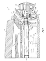
- an illuminated analog wristwatch shown generally as 1 , comprises a watchcase 2 containing a movement shown in outline form at 3 .
- Watchcase 2 is provided with a transparent lens 4 and caseback 5 with a sealing gasket 6 in a conventional construction.
- the movement 3 includes a timekeeping gear train (not shown) operatively connected to a stepping motor (not shown) drive watch hands 7 above a dial 8 supported on movement 3 .
- Movement 3 contains an energy cell 9 connected to various electronic components to supply power to the stepping motor driving the gear train, and also to supply power to an electroluminescent circuit providing illumination for the dial 8 .
- PCB printed circuit board
- electrically conductive spring plate 11 The details of the electrical circuits are not relevant to the present invention, except to note that an electroluminescent drive circuit is provided on the PCB which causes illumination of analog watch dial 8 when a switch is closed.
- a setting stem 12 is rotatably mounted and axially slidable within the movement 3 .
- the end of stem 12 is threaded at 12a and extends into an opening 2a in watchcase 2 .
- An external crown/pushbutton manual actuator 13 is disposed on the outside of watchcase 2 .
- Actuator 13 includes a knurled peripheral flange 13a connected to a central stub 13b having internal threads and fitted with an external sealing groove 13c .
- An 0-ring gasket 14 allows the actuator 13 to slide axially as well as rotate while preventing the entrance of dirt and moisture through the watchcase opening 2a .
- a circular recess 2b in the watchcase coaxial with flange 13a allows the actuator 13 to be pushed inward without interfering with the flange 13a .
- Stem 12 has a neck 12b with a groove 12c in which is disposed a snap-fit retaining member 15 .
- a resilient spring switching arm 16 which is supported from movement 3 , extends to neck 12b of the stem and provides a biasing spring force against retaining member 15 pushing stem 12 axially in an outward direction. Stem 12 is prevented from moving outward by other structure to be discussed later, so that it is retained in the "run" or normal position illustrated in Fig. 1 .
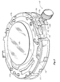
- movement 3 is shown inverted to illustrate the printed circuit board 10 being retained on a frame 17 by the spring plate 11 .
- the frame 17 is of plastic material and includes a number of posts 17c which are upset by ultrasonic welding.
- the resilient switching arm 16 is made by folding a tab down from the metal spring plate 11 and arranging it so that it will surround the neck 12b of the stem, so as to be engagable by the retaining member 15 on stem neck 12b .
- PCB 10 is of insulating material, but includes a peripheral conductive insert forming a first contact terminal 33 which is connected to other elements of the circuit.
- Another or second contact terminal 34 forming the second member of a switch is provided by an upward extension from resilient spring arm 16 and is spaced from contact terminal 33 . While the second contact terminal is shown disposed on the spring arm 16 , it could also be a separate member interposed between spring arm 16 and contact terminal 33 , and connected to ground.
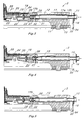
- Figs. 3, 4 , and 5 of the drawings the same elements are illustrated in each of the cross-sectional elevational drawings, the only difference between the figures being in the axial position of the stem 12 .
- the watchcase, dial, hands and actuator 13 are omitted for purpose of clarity.
- stem 12 is illustrated in the normal or "run” position.
- Fig. 4 stem 12 is illustrated having been pulled axially outward from the movement into the "setting” position.
- Fig. 5 the stem has been pushed axially inward toward the movement into the "switching" position.
- a frame 17 having a bore 17a within which stem 12 is axially slidable and also rotatable.
- Stem 12 carries a setting pinion 18 and a stem extension stub 19 , which makes grounding contact with a spring contact member 20 .
- Frame 17 carries gear train elements such as an hour wheel 21 , a center wheel 22 and a seconds wheel 23 , all having concentric shafts carrying the timekeeping hands (not shown).
- a setting gear 24 has spur teeth engaging the center wheel at 25 , and also has crown teeth 26 adapted to mesh with the setting pinion 18 when the stem 12 is in the Fig 4 setting position.
- Stem 12 carries a detent flange 27 beveled with a frusto-conical surface on either side thereof to cooperate with a detent spring 28 .
- Detent spring 28 is mounted so that it can rise into a slot 17b in the frame when stem 12 is slid axially.
- Stem 12 also includes a flat-faced retaining flange 29 .
- Flanges 27 and 29 establish a detent groove between them receiving the detent spring 28 so as to temporarily hold stem 12 in the setting position as shown in Fig. 4 .
- time setting pinion 18 is engaged with the crown teeth of setting gear 24 .
- a spring holding plate 30 may be included to assist in holding the gears 18, 24 in mesh and movable to prevent damage if they do not mesh properly when engaged.
- stem 12 is provided with a blocking flange 31 which has a flat radial face spaced from the detent flange 27 , so as to provide an axially elongated detent recess 32 .
- the detent recess 32 provides a pre-selected range of axial movement of the stem during which the hands are operated by the gear train in a normal manner while the detent spring 28 traverses detent recess 32 .
- Fig. 3 illustrates detent spring 28 in the left hand end of detent recess 32
- Fig. 5 illustrates detent spring 28 in the right hand end of detent recess 32 .
- the first contact terminal 33 is disposed adjacent stem 12 , and the second contact terminal 34 , which may be part of the switching arm 16 is spaced from the first contact terminal 33 .
- the axial spacing is selected to be less than the axial travel of stem 12 permitted by the aforementioned detent recess 32 .
- the invention operates as follows. In the run position illustrated in Fig. 3 , spring switching arm 16 presses against retaining member 15 and is trying to push stem 12 to the right, but it is prevented from moving by detent spring 28 riding against detent flange 27 .
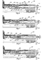
- FIG. 6 is the "run" position with a watch stem 36 shown having an additional detent flange 37 , and having a date ring 38 rotatably carried in movement 35 .
- a sleeve 39 making frictional engagement with the stem 36 includes radial teeth 40 meshing with inner spur teeth on date ring 38 .
- the additional detent flange 37 establishes together with detent flange 27 and detent spring 28 an axially intermediate date setting position between the run position and the setting position.
- Rotation of stem 36 through frictional engagement with sleeve 39 causes sleeve 39 to rotate and to advance or reverse the date ring 38 .
- FIG. 8 illustrates the stem 36 pulled out to the next or setting detenting position which is established by the detent spring 28 resting between flanges 29, 27 as before.
- Setting pinion 18 is engaged with setting wheel 24 and rotation of stem 36 sets the watch hands as before.
- FIG. 9 shows an axially elongated detent recess 40 , according to the present invention, which is now established between the additional detent flange 37 and blocking flange 31 .
- Detent recess 40 permits a preselected range of axial movement of stem 36 which is slightly greater than the spacing between the first contact member 33 and the first contact member 34 as previously described.
Landscapes
- Physics & Mathematics (AREA)
- General Physics & Mathematics (AREA)
- Electric Clocks (AREA)
- Switches With Compound Operations (AREA)
Claims (7)
- Montre analogique éclairée (1) avec une couronne et un bouton-poussoir, comportant un boítier de montre (2), un mouvement (3) disposé dans le boítier de montre (2) comportant un train d'engrenages (24, 22) et des aiguilles (7) actionnées par le train d'engrenages (24, 22), des moyens (10) pour éclairer la montre en réponse à la fermeture d'un commutateur, une tige rotative (12) disposée de manière coulissante dans le mouvement (3), un dispositif d'actionnement de couronne (13) disposé sur la tige (12) externe au boítier de montre (2) pour faire tourner et coulisser manuellement la tige (12), un pignon de réglage (18) disposé sur la tige (12), adapté pour faire venir en prise le train d'engrenages (24, 22) lorsque la couronne est tirée vers une position de réglage externe pour régler les aiguilles (7), un ressort à cliquet (28) coopérant avec la tige (12) pour maintenir temporairement la tige (12) dans la position de réglage externe, une cavité à cliquet axialement allongée (32) définie par ladite tige (12), agencée de manière à coopérer avec ledit ressort à cliquet (28) pour permettre une plage sélectionnée à l'avance de mouvement axial de ladite tige (12) pendant laquelle lesdites aiguilles (7) sont actionnées par ledit train d'engrenages (24, 22), entre une position d'avancement normal et une position de commutation axialement interne, une première borne de contact (33) adjacente à ladite tige (12) connectée comme un côté dudit commutateur et une deuxième borne de contact (34) espacée de ladite première borne de contact (33) connectée comme autre côté dudit commutateur,
dans laquelle un ressort de poussée est adapté pour coopérer avec ladite tige (12) et la pousse axialement vers l'extérieur vers ladite position d'avancement, caractérisée en ce que ledit ressort de poussée est un bras de commutation à ressort (16) qui, outre la poussée de la tige, est agencé de manière à faire en sorte que la deuxième borne de contact (34) fasse contact avec la première borne de contact (33), lorsque ladite tige (12) est déplacée à l'intérieur de ladite plage sélectionnée à l'avance de mouvement axial en poussant ladite couronne à l'encontre de la force de poussée dudit bras de commutation à ressort (16). - Combinaison selon la revendication 1, dans laquelle ladite tige (12) définit au moins une bride à cliquet (27) ayant des surfaces tronconiques sur l'un et l'autre de ses côtés et une bride de blocage (31) espacée de celle-ci de manière à définir ladite cavité à cliquet (32).
- Combinaison selon la revendication 2, dans laquelle ladite tige (12) définit une bride de retenue (29) sur le côté opposé de ladite bride à cliquet (27) par rapport à ladite bride de blocage (31), ladite bride de retenue (29) et ladite bride à cliquet (27) définissant une gorge entre elles, établissant ladite position de réglage externe.
- Combinaison selon la revendication 2, dans laquelle ladite tige (12) définit au moins une deuxième bride à cliquet (29) sur le côté opposé de ladite première bride à cliquet (27) par rapport à ladite bride de blocage (31), lesdites brides à cliquet (27, 29) définissant une gorge entre elles, établissant une position de réglage de date axialement intermédiaire.
- Combinaison selon la revendication 1, dans laquelle ledit mouvement (3) comporte une carte de circuit imprimé (10) comportant ladite première borne de contact (33) disposée sur un bord périphérique de celle-ci et comporte en outre une plaque à ressort conductrice (11) maintenant ladite carte de circuit imprimé (10), ledit bras de commutation à ressort (16) étant formé comme partie de ladite plaque à ressort conductrice (11) et espacée de ladite première borne de contact (33) pour fournir ladite deuxième borne de contact (34).
- Combinaison selon la revendication 1, comportant un élément de retenue (15) fixé à ladite tige (12) et adapté pour venir en contact avec ledit bras de commutation à ressort (16) pour transmettre la force de poussée de ressort provenant du bras de commutation à ressort (16) à la tige (12).
- Combinaison selon la revendication 1, dans laquelle ladite deuxième borne de contact (34) est disposée sur ledit bras de commutation à ressort (16).
Applications Claiming Priority (3)
| Application Number | Priority Date | Filing Date | Title |
|---|---|---|---|
| US387692 | 1995-02-13 | ||
| US08/387,692 US5644553A (en) | 1995-02-13 | 1995-02-13 | Combined crown/pushbutton for illuminated analog watch |
| PCT/IB1996/000290 WO1996025694A1 (fr) | 1995-02-13 | 1996-02-12 | Combinaison couronne/bouton-poussoir pour une montre analogique eclairee |
Publications (2)
| Publication Number | Publication Date |
|---|---|
| EP0809821A1 EP0809821A1 (fr) | 1997-12-03 |
| EP0809821B1 true EP0809821B1 (fr) | 2000-10-11 |
Family
ID=23530990
Family Applications (1)
| Application Number | Title | Priority Date | Filing Date |
|---|---|---|---|
| EP96906883A Expired - Lifetime EP0809821B1 (fr) | 1995-02-13 | 1996-02-12 | MONTRE ANALOGIQUE ECLAIREE avec COMBINAISON COURONNE/BOUTON-POUSSOIR |
Country Status (6)
| Country | Link |
|---|---|
| US (1) | US5644553A (fr) |
| EP (1) | EP0809821B1 (fr) |
| AU (1) | AU5012996A (fr) |
| CA (1) | CA2212737C (fr) |
| DE (1) | DE69610615T2 (fr) |
| WO (1) | WO1996025694A1 (fr) |
Families Citing this family (15)
| Publication number | Priority date | Publication date | Assignee | Title |
|---|---|---|---|---|
| DE29812104U1 (de) | 1998-07-09 | 1998-09-24 | Greiner Vollelektronische Quarz-Uhren GmbH, 64832 Babenhausen | Mondphasenuhr, insbesondere Mondphasenuhr mit elektromechanischem Quarzuhrwerk |
| US6146010A (en) * | 1999-03-08 | 2000-11-14 | Timex Corporation | Combined crown and pusher electro mechanism |
| US6203190B1 (en) | 1999-06-07 | 2001-03-20 | Timex Corporation | Crown switching mechanism |
| EP1416343A1 (fr) | 2002-10-28 | 2004-05-06 | ETA SA Manufacture Horlogère Suisse | Dispositif de commande pour poussoir, notamment de pièce d'horlogerie, et instrument électronique portable comprenant un tel dispositif |
| CN1708734B (zh) * | 2002-10-28 | 2010-09-01 | Eta瑞士钟表制造股份有限公司 | 按钮控制装置以及包含该装置的便携式电子仪器 |
| JP4688511B2 (ja) * | 2005-02-04 | 2011-05-25 | セイコーインスツル株式会社 | リセット電流導通構造を備えたアナログ電子時計 |
| EP2072008A3 (fr) * | 2007-12-19 | 2013-04-17 | Beppo Hilfiker | Dispositif destiné à la commande d'un appareil électronique multifonction |
| EP2275882A1 (fr) * | 2009-07-14 | 2011-01-19 | ETA SA Manufacture Horlogère Suisse | Dispositif de blocage d'un mouvement d'une pièce d'horlogerie |
| US8439559B2 (en) * | 2010-03-23 | 2013-05-14 | Bright Aggregation Technology Limited | Timepiece with multi-functional actuator |
| US9519273B2 (en) * | 2014-03-06 | 2016-12-13 | Seiko Epson Corporation | Electronic timepiece and movement |
| JP6405782B2 (ja) * | 2014-08-08 | 2018-10-17 | セイコーエプソン株式会社 | スイッチばね、ムーブメント、電子時計 |
| JP6820439B2 (ja) * | 2017-04-18 | 2021-01-27 | タイメックス グループ ユーエスエイ,インコーポレイテッド | クラウンプッシャーアセンブリ及びそれを備えた手首装着型電子デバイス |
| JP7087421B2 (ja) * | 2018-02-05 | 2022-06-21 | セイコーエプソン株式会社 | 電子時計 |
| JP7211061B2 (ja) * | 2018-12-19 | 2023-01-24 | カシオ計算機株式会社 | 押釦装置及び時計 |
| CN115291492B (zh) * | 2022-08-11 | 2023-09-01 | 广东古尊科技有限公司 | 用于手表的上条机构 |
Family Cites Families (11)
| Publication number | Priority date | Publication date | Assignee | Title |
|---|---|---|---|---|
| FR1203096A (fr) * | 1958-07-08 | 1960-01-15 | Montres Solvil Et Titus Fab De | Montre éclairée |
| US3526088A (en) * | 1968-06-21 | 1970-09-01 | Timex Corp | Watch setting crown mechanism |
| US3832843A (en) * | 1974-02-20 | 1974-09-03 | Timex Corp | Electric alarm timepiece |
| JPS5619743Y2 (fr) * | 1974-12-26 | 1981-05-11 | ||
| US4031341A (en) * | 1976-01-14 | 1977-06-21 | Timex Corporation | Dual function pusher and rotate switch for solid state digital watches having detent spring |
| US4023002A (en) * | 1976-01-14 | 1977-05-10 | Timex Corporation | Pusher and switch device for electronic watch |
| JPS5386284A (en) * | 1976-12-13 | 1978-07-29 | Citizen Watch Co Ltd | Crystal timepiece |
| DE3113019C1 (de) * | 1981-04-01 | 1982-10-07 | Gebrüder Junghans GmbH, 7230 Schramberg | Stellwellen-Stellvorrichtung fuer Minuten- und Stundenzeiger einer elektronischen Armbanduhr |
| US4536095A (en) * | 1984-09-13 | 1985-08-20 | Timex Corporation | Crown setting switch for a wristwatch |
| US4794576A (en) * | 1988-01-29 | 1988-12-27 | Timex Corporation | Combination electrical contact member and braking member for a timepiece |
| US5305291A (en) * | 1993-09-22 | 1994-04-19 | Timex Corporation | Alarm setting and actuating mechanism for analog timepiece |
-
1995
- 1995-02-13 US US08/387,692 patent/US5644553A/en not_active Expired - Lifetime
-
1996
- 1996-02-12 AU AU50129/96A patent/AU5012996A/en not_active Abandoned
- 1996-02-12 WO PCT/IB1996/000290 patent/WO1996025694A1/fr not_active Ceased
- 1996-02-12 DE DE69610615T patent/DE69610615T2/de not_active Expired - Fee Related
- 1996-02-12 CA CA002212737A patent/CA2212737C/fr not_active Expired - Fee Related
- 1996-02-12 EP EP96906883A patent/EP0809821B1/fr not_active Expired - Lifetime
Also Published As
| Publication number | Publication date |
|---|---|
| CA2212737C (fr) | 2004-06-01 |
| DE69610615T2 (de) | 2001-05-10 |
| WO1996025694A1 (fr) | 1996-08-22 |
| AU5012996A (en) | 1996-09-04 |
| DE69610615D1 (de) | 2000-11-16 |
| US5644553A (en) | 1997-07-01 |
| EP0809821A1 (fr) | 1997-12-03 |
| CA2212737A1 (fr) | 1996-08-22 |
Similar Documents
| Publication | Publication Date | Title |
|---|---|---|
| EP0809821B1 (fr) | MONTRE ANALOGIQUE ECLAIREE avec COMBINAISON COURONNE/BOUTON-POUSSOIR | |
| US5742565A (en) | Crown setting device for a timepiece | |
| US3978296A (en) | Switching system for an electronic timepiece | |
| US6672758B2 (en) | Electric device for switching between at least three different contacts | |
| JP3647808B2 (ja) | 竜頭スイッチ機構 | |
| US4536095A (en) | Crown setting switch for a wristwatch | |
| EP0655665B1 (fr) | Montre et son mecanisme de commutation d'affichage | |
| US3824782A (en) | Correction switching device of wrist watch with electronic buzzer | |
| CA1072750A (fr) | Horloge electronique munie d'un commutateur a poussoir actionne par came | |
| JPS55119324A (en) | Switching structure for watch | |
| DE3865823D1 (de) | Datumsanzeige. | |
| US5253227A (en) | Time-piece | |
| EP3612899B1 (fr) | Ensemble poussoir de couronne et dispositif électronique portable sur le poignet le comprenant | |
| US4504154A (en) | Indexing element for switching a chronometer | |
| US2024162A (en) | Control mechanism | |
| US1583760A (en) | Clock-controlled switch | |
| HK1000048A1 (zh) | 模擬指針式計時器的響鬧及啟動裝置 | |
| FR2337364B1 (fr) | ||
| JPS5530675A (en) | Switch structure for watch | |
| JPS59681A (ja) | 時計 | |
| GB1225752A (fr) | ||
| JPH0634044B2 (ja) | タイムスイッチ | |
| GB2265731A (en) | Dual alarm analogue clock | |
| JPS57149986A (en) | Time setter | |
| HK1013867B (en) | Timepiece and its display switching mechanism |
Legal Events
| Date | Code | Title | Description |
|---|---|---|---|
| PUAI | Public reference made under article 153(3) epc to a published international application that has entered the european phase |
Free format text: ORIGINAL CODE: 0009012 |
|
| 17P | Request for examination filed |
Effective date: 19970912 |
|
| AK | Designated contracting states |
Kind code of ref document: A1 Designated state(s): CH DE FR GB LI |
|
| 17Q | First examination report despatched |
Effective date: 19980914 |
|
| RTI1 | Title (correction) |
Free format text: ILLUMINATED ANALOG WATCH WITH COMBINED CROWN/PUSHBUTTON |
|
| RTI1 | Title (correction) |
Free format text: ILLUMINATED ANALOG WATCH WITH COMBINED CROWN/PUSHBUTTON |
|
| GRAG | Despatch of communication of intention to grant |
Free format text: ORIGINAL CODE: EPIDOS AGRA |
|
| 17Q | First examination report despatched |
Effective date: 19980914 |
|
| GRAG | Despatch of communication of intention to grant |
Free format text: ORIGINAL CODE: EPIDOS AGRA |
|
| GRAH | Despatch of communication of intention to grant a patent |
Free format text: ORIGINAL CODE: EPIDOS IGRA |
|
| GRAH | Despatch of communication of intention to grant a patent |
Free format text: ORIGINAL CODE: EPIDOS IGRA |
|
| GRAA | (expected) grant |
Free format text: ORIGINAL CODE: 0009210 |
|
| AK | Designated contracting states |
Kind code of ref document: B1 Designated state(s): CH DE FR GB LI |
|
| REG | Reference to a national code |
Ref country code: CH Ref legal event code: EP |
|
| REF | Corresponds to: |
Ref document number: 69610615 Country of ref document: DE Date of ref document: 20001116 |
|
| ET | Fr: translation filed | ||
| REG | Reference to a national code |
Ref country code: CH Ref legal event code: NV Representative=s name: ISLER & PEDRAZZINI AG |
|
| PGFP | Annual fee paid to national office [announced via postgrant information from national office to epo] |
Ref country code: GB Payment date: 20010205 Year of fee payment: 6 |
|
| PLBE | No opposition filed within time limit |
Free format text: ORIGINAL CODE: 0009261 |
|
| STAA | Information on the status of an ep patent application or granted ep patent |
Free format text: STATUS: NO OPPOSITION FILED WITHIN TIME LIMIT |
|
| 26N | No opposition filed | ||
| PG25 | Lapsed in a contracting state [announced via postgrant information from national office to epo] |
Ref country code: FR Free format text: LAPSE BECAUSE OF NON-PAYMENT OF DUE FEES Effective date: 20011031 |
|
| REG | Reference to a national code |
Ref country code: FR Ref legal event code: ST |
|
| PG25 | Lapsed in a contracting state [announced via postgrant information from national office to epo] |
Ref country code: DE Free format text: LAPSE BECAUSE OF NON-PAYMENT OF DUE FEES Effective date: 20011201 |
|
| REG | Reference to a national code |
Ref country code: GB Ref legal event code: IF02 |
|
| PG25 | Lapsed in a contracting state [announced via postgrant information from national office to epo] |
Ref country code: GB Free format text: LAPSE BECAUSE OF NON-PAYMENT OF DUE FEES Effective date: 20020212 |
|
| GBPC | Gb: european patent ceased through non-payment of renewal fee |
Effective date: 20020212 |
|
| REG | Reference to a national code |
Ref country code: CH Ref legal event code: PCAR Free format text: ISLER & PEDRAZZINI AG;POSTFACH 1772;8027 ZUERICH (CH) |
|
| PGFP | Annual fee paid to national office [announced via postgrant information from national office to epo] |
Ref country code: CH Payment date: 20150226 Year of fee payment: 20 |
|
| REG | Reference to a national code |
Ref country code: CH Ref legal event code: PL |