EP0810083B1 - Presse à balles - Google Patents
Presse à balles Download PDFInfo
- Publication number
- EP0810083B1 EP0810083B1 EP19970650020 EP97650020A EP0810083B1 EP 0810083 B1 EP0810083 B1 EP 0810083B1 EP 19970650020 EP19970650020 EP 19970650020 EP 97650020 A EP97650020 A EP 97650020A EP 0810083 B1 EP0810083 B1 EP 0810083B1
- Authority
- EP
- European Patent Office
- Prior art keywords
- chamber
- bale
- baling press
- bar
- floor
- Prior art date
- Legal status (The legal status is an assumption and is not a legal conclusion. Google has not performed a legal analysis and makes no representation as to the accuracy of the status listed.)
- Expired - Lifetime
Links
- 238000005056 compaction Methods 0.000 claims description 49
- 239000002699 waste material Substances 0.000 claims description 21
- 238000003780 insertion Methods 0.000 claims description 2
- 230000037431 insertion Effects 0.000 claims description 2
- 230000007246 mechanism Effects 0.000 description 9
- 230000003068 static effect Effects 0.000 description 6
- 239000000463 material Substances 0.000 description 4
- 238000000034 method Methods 0.000 description 4
- 238000013459 approach Methods 0.000 description 1
- 230000001427 coherent effect Effects 0.000 description 1
- 230000001419 dependent effect Effects 0.000 description 1
- 238000013461 design Methods 0.000 description 1
- 230000005484 gravity Effects 0.000 description 1
- 238000012423 maintenance Methods 0.000 description 1
- 230000001360 synchronised effect Effects 0.000 description 1
Images


Classifications
-
- B—PERFORMING OPERATIONS; TRANSPORTING
- B30—PRESSES
- B30B—PRESSES IN GENERAL
- B30B9/00—Presses specially adapted for particular purposes
- B30B9/30—Presses specially adapted for particular purposes for baling; Compression boxes therefor
- B30B9/3003—Details
- B30B9/3014—Ejection means
Definitions
- the present invention concerns baling presses of the type used to crush and compress loose waste materials such as discarded wrappers for example, so as to form coherent blocks of densified material which may be handled as unitized loads by conventional handling equipment such as stillage trucks, or hoists for example.
- a baling press having the features as set forth in the preamble portion of claim 1 is known for example from EP-A-0,562,312.
- the present specification describes an improved means for ejecting blocks of densified waste material from the compaction chambers of otherwise-conventional baling presses and optionally includes a means for producing blocks of waste material which are more easily handled by mechanical means than those produced hitherto.
- waste material is typically allowed to slide or fall into an open-topped box-like compaction chamber, and periodically a hydraulically-powered plunger which is mounted above the chamber is caused to move downwardly until it enters the chamber where it crushes and compresses the waste material against the flat bottom face (or floor) of the chamber.
- the plunger is then caused to withdraw to its idle position above the compaction chamber, exposing the partially-filled chamber for the addition of further loose waste materials.
- the shape and dimensions of the plunger in a baling press are similar to those of the compaction chamber, the plunger typically being a sliding fit inside the chamber.
- the above process is repeated until the chamber is filled with densified waste material when, with the plunger pressing downwardly so as to prevent the materials in the chamber from springing-back or partially recovering their shape, one or more bands or straps are tied around the bundle (through slits or grooves in the sides and floor of the chamber, and sometimes also in the face of the plunger).
- the plunger is then withdrawn to its idle position and one side of the baling chamber is removed (usually it is hinged like a door) so as to expose the densified unitized bale of waste material.
- the size and weight of the bale is obviously dependent upon the nature of the waste material and the size of the compaction chamber, but typically the bale will weigh between one hundred and one thousand kilograms, and it will therefore be too heavy to be manhandled.
- a baling press is provided with mechanical means for assisting with the removal of the bale from the chamber.
- a means might take the form of a mechanism for tilting the bale upwardly about its bottom edge adjacent to the open side of the chamber, so as partially to tip or roll the bale so that it may be pulled manually out of the chamber and dropped upon its side onto a flat truck or across stillage (or lift truck) forks previously positioned in front of the opened side of the chamber, whence the bale may be removed.
- conventional compaction chambers are sometimes slightly tapered, being narrowest at the side opposite to the open side and widest at the open side.
- bales become jammed during ejection from the chamber, requiring physically tiring and potentially dangerous manual intervention. Also it usually happens that bales which have been tipped onto their sides are unstable and tend to fall over while they are being transported away from the baling press.
- bales do not always land in a stable attitude upon the flat truck or stillage forks, and during transit away from the baling press they often roll over or slide sideways and fall to the ground, which is both inconvenient and potentially dangerous.
- a baling press having a compaction chamber and an ejection means for ejecting a compressed bale of waste-material from the compaction chamber of the baling press, said chamber comprising a floor and side walls defining an opening at the front of the chamber through which the bale may be ejected
- the ejection means comprises a carriage member slideable in guide means formed in the floor and extending linearly of the floor from the rear of the chamber towards said opening, and an ejector plate mounted on said carriage member and being moveable with the carriage member so as to move a bale towards said opening, characterised by a linearly reciprocating push member which in operation of the baling press is caused to reciprocate continuously, drive means for said push member and means for intermittently transmitting drive from said reciprocating push member to the carriage member so as to cause the carriage member and ejector plate to travel incrementally from the rear of the compaction chamber towards the front.
- the means for intermittently transmitting drive from the reciprocating push member is caused to reverse direction at the end of the forward path of travel of the ejector plate so as to cause the carriage member and the ejector plate to travel incrementally in reverse direction from the front of the compaction chamber towards the rear of the chamber after ejection of a bale from the compaction chamber.
- the push member preferably comprises a reciprocating bar and the means for intermittently transmitting drive from the bar to the carriage member comprises a ratchet incorporated in the bar and engageable with a double-sided pawl pivotally mounted on the carriage member.
- the compaction chamber comprises open-topped box-shaped compaction chamber assembled from side panels, a rear panel, a removable front panel and a floor member.
- the floor member is divided by a straight linear slot along which a carriage member upon which is fixed an upwardly projecting ejector plate is free to travel, and beneath and parallel with said slot is located a notched or serrated bar member which may be caused by a driving means to reciprocate continuously through a relatively short distance along its linear axis, said carriage member and said notched or serrated bar being supported and guided by fixed linear bearings; and pivoted to the underside of said carriage member is a double-sided pawl member which is so disposed that it may engage with the notches or serrations on the reciprocating notched or serrated bar, the assembly being so proportioned that the carriage is caused to travel in sympathy with the reciprocating bar when it travels in one direction but the pawl rides over the tops of the notches or serrations when the reciprocating bar travels in the opposite direction, thus causing the carriage and the floor member
- the driving means is an hydraulic cylinder, but optionally it may be a manual lever, or a hydraulically or electrically-driven crank or other linkage.
- An optional embodiment on the basic design is characterised in that the floor, or one of the side walls, of the compaction chamber, is provided with at least two substantially parallel spaced-apart formers which are raised above the surface of said floor or side walls and which are adapted to form at least two substantially parallel spaced-apart longitudinal grooves in a surface of the bale as the bale is compressed in the baling chamber.
- the formers are positioned in the floor so when the bale is ejected the bale is in the right orientation for easy removal by mechanical means.
- the formers comprise raised strips extending longitudinally of the floor or one of said side walls and an upper surface of each strip having a groove extending longitudinally thereof.
- two of said raised strips are so spaced apart that they coincide with the spacing of the forks of a lift truck.
- said two raised strips have such a profile that the impressions or indents made by strips in a bale of waste material will coincide with the profiles of the forks of a lift truck.
- the two strips are substantially equispaced to either side of the centerline of the chamber.
- the axial centerlines of said raised strips are substantially aligned with banding slits in the front and rear panels of said chamber, and the uppermost surfaces of the raised strips should preferably be provided with recesses whose purpose is to locate and guide banding tapes.
- a third raised strip may be provided substantially mid-way between said two raised strips, the third raised strip having such a profile that the impression made by said strip in a bale of waste material will facilitate the insertion of a sling for handling said bale by a crane or hoist.
- the raised strips may be so mounted upon the floor of the compaction chamber that they are mechanically retractable to a folded position wherein the uppermost surfaces of said strips are substantially flush with, or below the surface of the adjacent floor.
- bales produced in a baling chamber constructed according to this embodiment will be impressed with grooves which will facilitate the ejection of bales onto the forks and/or slings, the grooves further tending to prevent the bales from slipping sideways during handling by a lift truck or a crane or hoist.
- FIG. 1a and 1b there is seen an open-topped compaction chamber 1 which is constructed according to the invention.
- the chamber 1 is assembled from fixed side panels 2, a fixed back panel 3, a removable front panel 4, and a carriage member 6 is free to slide along, and is guided by, a linear slot 17 which runs centrally across the floor member 5 between the back panel 3 and the front of the chamber 7.
- An ejector plate 8 is securely mounted atop the carriage member 6 such that it projects upwardly into the compaction chamber 1.
- a second linear guideway 9 is located directly beneath the slot in the floor member 5, and a bar 10 is free to slide along and be guided by this second guideway 9, urged to and fro by an hydraulic cylinder 11 which is pivotally mounted upon the base 12 of the machine.
- a ram 18 of the cylinder 11 is bolted to a bracket 19 is fixed to and depends below the bar 10.
- the top surface of the bar 10 is provided with regularly spaced notches or serrations 13, and a double-sided pawl member 14, which is suspended from a pivot 15 beneath the carriage 6, is so disposed that it engages with the notches 13 on the surface of the bar 10.
- Control inputs are communicated to the PLC via an operator's control panel which contains a number of switches for starting or stopping the compaction or ejection systems.
- a number of sensor switches are also provided as inputs to the PLC to ensure the correct operation of the baling press and the safety of operators.
- An example of such a sensor switch is the one herein before mentioned to prevent the ejector plate, having ejected a bale and retracted fully from moving incrementally towards the front.
- Another example of such sensor switches would be those used to determine when the ram was fully extended and when it was retracted. It will be appreciated that a number of alternatives will be available to control the operation of the baling press and/or integrated ejection mechanism. One such alternative would be to replace the PLC with a set of relays connected to achieve the same result.
- the hydraulic cylinder could be replaced optionally by an electrically-driven crank mechanism or by a quick-return linkage, or by a manual lever or an alternative hydraulic cylinder attached to an arm fixed to a transverse shaft projecting beneath one side of the compaction chamber.
- two identical ejection mechanisms could be fitted side-by-side inside a single compaction chamber, synchronised by a transverse shaft and driven by a single actuator, in order to cope with particularly difficult materials which do not eject easily.
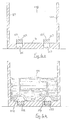
- FIG. 3a An alternative configuration is disclosed by referring first to Figure 3a, there is seen an empty open-topped box-shaped compaction chamber having two fixed side panels, a fixed back panel 3 and a removable front panel 4 supported upon hinges 106, and a floor 5. It is clear that the compaction chamber will include the ejection means described above. However this is omitted from the drawings to simplify the description of this embodiment. Two substantially parallel spaced-apart raised strips 108 and 110 are fixed to the floor 5, strips 108 and 110 being substantially equispaced to either side of the central axis.
- slits 111 are provided in the front and back panels 4 and 3, (and would also be present in the ejection plate (not shown)) and grooves 112 are provided centrally along the apices of the raised strips 108 and 110, the respective slits 111 and grooves 112 being aligned when the removable front panel 4 is in its closed operative position.
- banding straps 114 are laid along the grooves 112, and are allowed to project through the slits 111 in the front and rear panels 4 and 3 respectively and in the corresponding slits in the ejection plate.
- Loose waste material may then be dropped into the chamber 101 and from time to time, whenever the chamber begins to fill up, a flat-faced plunger or press (not shown) is driven downwardly into the chamber 101 in order to crush and compress the waste material, and the plunger is then withdrawn to its idle position above the chamber in order to allow further loose waste material to be dropped into the chamber 1 on top of that already compacted.
- a flat-faced plunger or press (not shown) is driven downwardly into the chamber 101 in order to crush and compress the waste material, and the plunger is then withdrawn to its idle position above the chamber in order to allow further loose waste material to be dropped into the chamber 1 on top of that already compacted.
- the banding straps 114 are passed back through the slits 111 in the front panel 4, across the top surface of the waste material, and out through the slits 111 in the back panel 3.
- the plunger is then driven downwardly to compress the previously crushed waste and to hold it in this position and prevent it from springing back while the respective ends of the banding straps 114, which are projecting through the slits 111 in the back panel 3, are tied or clipped together.
- the plunger is then withdrawn, the front panel 4 is removed by hinging it out of the way, and the bale 113 is ejected from the chamber 1 by the ejection means herein before described.
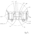
- FIG. 4a there is seen a side sectional view through an alternative embodiment of the invention, in which the empty chamber 118 is viewed from the back towards the front, the front panel having been removed.
- Figure 4b shows the same sectional view through the same chamber 118 in which a bale 126 has just been formed substantially in accordance with the procedure described above.
- the strips 122 and 123 have been retracted into recesses 126 and 127 respectively in the floor 121 of the chamber 118 by a mechanism (not shown), thus exposing the ends of the slots 128 and 129 respectively in the bottom surface of the bale 126.
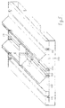
- the carriage member 6 is free to move along and is guided by a guideway or linear slot 17 formed by two longtitudal plates 201 and 202 which run from the back to the front.
- the ejector plate 8 is securely mounted atop the carriage member 6, such that it projects upwardly.
- the ejector plate is shaped so as to fit between the formers 108 and 110 and to enable it to move freely along the slot 17 formed by plates 201,202.
- the grooves 112 are provided to each side of the formers facilitate strapping of the bale with wires or the like.
- guide pins 205 fixed to the bar 10 and extending downwards through linear slots 207 ensure the linear motion of the bar 10.
- Hooks 206 are provided on the lower front edge of the compaction chamber to facilitate the locking of a pallet truck in position while a bale is ejected from the machine.
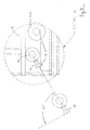
- a detail of the carriage member 6 in figure 6 is shown in figure 7.
- a pawl 14 is shaped so as to engage grooves 13 in the bar 10 and to facilitate the incremental movement of the carriage hereinbefore described by references to figure 2.
- Guide wheels 210 ensure that the carriage member 6 will not rise when the bar 10 is effecting movement of the carriage member 6 via the engagement of the pawl 14 with a groove 13.
- plates 201,202 which extend longtitudally from the front 7 to the rear of the chamber 3 and which form a linear guideway 17 restrict the upper progress of the guidewheels 210.
- the plates are fixed in position through the use of nuts 214 and bolts 213 which facilitate the removal of plates 201, 202 for maintenance purposes.
- bales may be produced in a shape such that the bales so produced are more easily and securely handled that heretofore by conventional mechanical handling equipment in particular by fork lift trucks, cranes and hoists.
Landscapes
- Engineering & Computer Science (AREA)
- Mechanical Engineering (AREA)
- Refuse Collection And Transfer (AREA)
- Processing Of Solid Wastes (AREA)
- Press Drives And Press Lines (AREA)
Claims (10)
- Presse à balles comprenant une chambre de compactage (1) et un moyen d'éjection pour éjecter un ballot de déchets comprimé depuis la chambre de compactage (1) de la presse à balles, ladite chambre comportant un plancher (5) et des parois latérales (2, 3) définissant à l'avant de la chambre une ouverture par laquelle la balle peut être éjectée, le moyen d'éjection comprenant un élément formant chariot (6) pouvant coulisser dans un moyen de guidage (17) formé dans le plancher (5) et s'étendant linéairement par rapport au plancher (5) depuis l'arrière de la chambre vers ladite ouverture, et une plaque d'éjection (8) montée sur ledit élément formant chariot (6) et mobile avec l'élément formant chariot (6) de façon à transporter une balle vers ladite ouverture, caractérisée par un élément pousseur (10) à mouvement alternatif linéaire qui, lors du fonctionnement de la presse à balles, est amené à aller et venir de façon continue, des moyens d'entraínement (11, 18) pour ledit élément pousseur (10) et des moyens (13, 14) pour transmettre par intermittence le mouvement d'entraínement dudit élément pousseur à va-et-vient (10) à l'élément formant chariot (6) de manière à amener l'élément formant chariot (6) et la plaque d'éjection (8) à se déplacer pas-à-pas depuis l'arrière de la chambre de compactage vers l'avant.
- Presse à balles selon la revendication 1, caractérisée en ce que les moyens (13, 14) pour transmettre de manière intermittente le mouvement d'entraínement depuis l'élément pousseur (10) à va-et-vient sont amenés à inverser le sens de marche à la fin de la course en marche avant de la plaque d'éjection (8) afin d'amener l'élément formant chariot (6) et la plaque d'éjection (8) à se déplacer pas-à-pas en sens inverse depuis l'avant de la chambre de compactage vers l'arrière de la chambre après l'éjection d'une balle depuis la chambre de compactage (1).
- Presse à balles selon la revendication 1 ou la revendication 2, caractérisée en ce que l'élément pousseur comporte une barre à va-et-vient (10) et les moyens pour transmettre de manière intermittente le mouvement d'entraínement de la barre (10) à l'élément formant chariot (6) comportent une roue à rochet (13) intégrée dans la barre (10) et pouvant coopérer avec un cliquet (4) à double face monté de manière pivotante sur l'élément formant chariot (6).
- Presse à balles selon l'une quelconque des revendications précédentes, caractérisée en ce que le plancher (5) est divisé par une fente linéaire rectiligne (17) le long de laquelle l'élément formant chariot (6), sur lequel est fixée une plaque d'éjection (8) faisant saillie vers le haut, circule librement, et sous ladite fente et parallèlement à celle-ci se trouve un élément formant barre (10) à encoches ou crans qui, par un moyen d'entraínement (11, 18), peut être amené à aller et venir de façon continue sur une distance relativement courte sur son axe linéaire, ledit élément formant chariot (6) et ladite barre (10) à encoches ou à crans étant supportés et guidés par des paliers linéaires fixes ; et sur la face inférieure dudit élément formant chariot (6) pivote un élément formant cliquet (14) à double face qui est disposé de façon à pouvoir s'engager dans les encoches ou les crans (13) de la barre à va-et-vient (10) à encoches ou crans, l'ensemble étant agencé et dimensionné de façon que l'élément formant chariot (6) soit amené à circuler en synchronisme avec la barre à va-et-vient (10) lorsqu'il se déplace dans un premier sens, mais que le cliquet (14) passe sur le haut des encoches ou des crans (13) lorsque la barre à va-et-vient (10) se déplace en sens inverse, ce qui amène le chariot et la plaque d'éjection à se déplacer pas-à-pas depuis l'arrière de la chambre de compaction (1) vers l'avant, lorsque le cliquet (14) retombe au-delà de l'extrémité de, ou dans un évidement de la face de la barre à va-et-vient (10) et est ainsi amené à se trouver en regard de la direction opposée pour qu'un va-et-vient continu de la barre (10) à encoches ou crans amène l'élément formant chariot (6) à revenir pas-à-pas vers l'arrière de la chambre (1).
- Presse à balles selon l'une quelconque des revendications précédentes, caractérisée en ce que le moyen d'entraínement est un vérin hydraulique (11, 18) ou éventuellement est un levier manuel, ou une manivelle à commande hydraulique ou électrique.
- Presse à balles selon l'une quelconque des revendications 1 à 5, caractérisée en ce que le fond (5, 21) et/ou une desdites parois latérales (2, 3, 4, 5 ; 119, 120) est pourvu d'au moins deux éléments conformateurs sensiblement parallèles espacés l'un de l'autre (108, 110 ; 126, 127) qui dépassent au-dessus de la surface dudit plancher (107, 121) ou de ladite paroi latérale (2, 3, 4, 5 ; 119, 120) et qui sont aptes à former au moins deux rainures longitudinales sensiblement parallèles espacées l'une de l'autre (115, 117 ; 128, 129) dans une surface de la balle (113) à mesure que la balle (113) est comprimée dans la chambre (101) de formation de balles.
- Presse à balles selon la revendication 6, caractérisée en ce que les éléments conformateurs comportent des bandes saillantes (108, 110 ; 126, 127) qui s'étendent longitudinalement par rapport au plancher (107, 121) et/ou une desdites parois latérales (2, 3, 4, 5 ; 119, 120) et une surface supérieure de chaque bande ayant une rainure (12) qui s'étend longitudinalement par rapport à elle.
- Presse à balles selon la revendication 6 ou la revendication 7, caractérisée en ce que deux des éléments conformateurs saillants (108, 110 ; 122, 123) sont situés dans un plancher (5 ; 21) de la chambre et sont espacés l'un de l'autre et profilés de façon à coïncider sensiblement avec l'espacement et le profil des fourches d'un chariot élévateur, sensiblement à équidistance de part et d'autre d'un axe central de la chambre (1), et sensiblement alignés avec des fentes de cerclage (111) dans les panneaux avant et arrière de la chambre.
- Presse à balles selon l'une quelconque des revendications 6 à 8, caractérisée en ce que les éléments conformateurs saillants (122, 123) sont escamotables d'une position saillante à une position rentrée dans laquelle les surfaces supérieures des bandes sont sensiblement au même niveau que, ou sous le niveau de la surface adjacente du plancher (21) ou des parois latérales (2, 3, 4, 5 ; 119, 120).
- Presse à balles selon l'une quelconque des revendications 6 à 9, caractérisée en ce qu'un troisième élément conformateur saillant est disposé sensiblement à mi-distance entre lesdits deux éléments conformateurs saillants (108, 110), le troisième élément conformateur saillant (109) ayant un profil tel que l'impression qu'il laisse dans une balle de déchets facilite l'insertion d'une élingue pour manipuler la balle à l'aide d'une grue ou d'un palan.
Applications Claiming Priority (4)
| Application Number | Priority Date | Filing Date | Title |
|---|---|---|---|
| IE960384 | 1996-05-30 | ||
| IES960384 IES960384A2 (en) | 1996-05-30 | 1996-05-30 | A compaction chamber of a baling press |
| IES960385 IES77628B2 (en) | 1996-05-30 | 1996-05-30 | A baling press |
| IE960385 | 1996-05-30 |
Publications (3)
| Publication Number | Publication Date |
|---|---|
| EP0810083A2 EP0810083A2 (fr) | 1997-12-03 |
| EP0810083A3 EP0810083A3 (fr) | 1998-02-04 |
| EP0810083B1 true EP0810083B1 (fr) | 2003-10-15 |
Family
ID=26319924
Family Applications (1)
| Application Number | Title | Priority Date | Filing Date |
|---|---|---|---|
| EP19970650020 Expired - Lifetime EP0810083B1 (fr) | 1996-05-30 | 1997-05-29 | Presse à balles |
Country Status (2)
| Country | Link |
|---|---|
| EP (1) | EP0810083B1 (fr) |
| DE (1) | DE69725503D1 (fr) |
Cited By (1)
| Publication number | Priority date | Publication date | Assignee | Title |
|---|---|---|---|---|
| DE202009011314U1 (de) | 2009-08-14 | 2010-01-14 | Schwelling, Hermann | Ballenpresse |
Families Citing this family (8)
| Publication number | Priority date | Publication date | Assignee | Title |
|---|---|---|---|---|
| US6474226B1 (en) * | 2000-02-02 | 2002-11-05 | Loadking Manufacturing Co. | Baling apparatus and method |
| AUPS125102A0 (en) * | 2002-03-21 | 2002-04-18 | Byrne Trailer Manufacturing (Wagga Wagga) Pty Limited | Improved compactor system |
| DE102004002730A1 (de) * | 2004-01-20 | 2005-08-18 | Deere & Company, Moline | Ballenpresse |
| AT508287B1 (de) * | 2009-06-04 | 2012-04-15 | Roither Maschinenbau Gesmbh | Vorrichtung zum pressen und fördern von ballen, insbesondere aus altstoffen |
| BE1018947A3 (nl) * | 2009-10-07 | 2011-11-08 | Cnh Belgium Nv | Een pin voor een uitwerpinrichting van een rechthoekige balenpers. |
| DE102013017315A1 (de) * | 2013-10-18 | 2015-04-23 | Sib Strautmann Ingenieurbüro Gmbh | Verfahren zum Erzeugen von Pressballen und Ballenpresse |
| BE1022659B1 (nl) | 2015-03-05 | 2016-06-29 | Cnh Industrial Belgium Nv | Balenpers voor gebruik in de landbouw met een gedeeltelijke baaluitstoter |
| WO2017023234A1 (fr) * | 2015-07-31 | 2017-02-09 | Chacon Ysidro | Compacteur de presse à balles de carton portable |
Family Cites Families (7)
| Publication number | Priority date | Publication date | Assignee | Title |
|---|---|---|---|---|
| US2714968A (en) * | 1952-10-30 | 1955-08-09 | New Holland Machine Division O | Wagon unloader ejector mechanism |
| US4092912A (en) * | 1976-06-11 | 1978-06-06 | A. J. Gerrard & Company | Press platen wedges |
| US4549840A (en) * | 1984-04-02 | 1985-10-29 | Jan Ansbjer | Self-loading carriage for round bales |
| US5314290A (en) * | 1991-10-04 | 1994-05-24 | Lutz David E | Cargo carrying vehicle having a movable bulkhead located therein |
| US5247880A (en) * | 1992-03-26 | 1993-09-28 | Marathon Equipment Company | Horizontal baler with movable bottom support ejector |
| DE9300054U1 (de) * | 1993-01-05 | 1993-02-25 | Fortschritt Erntemaschinen GmbH, O-8355 Neustadt | Ballenausdrückvorrichtung an landwirtschaftlichen Ballenpressen |
| DE29615598U1 (de) * | 1996-09-06 | 1996-12-19 | Strautmann Umwelttechnik und Recycling Gesellschaft mbH und Co.KG, 49326 Melle | Preßschild und Auswerfer für Ballenpresse |
-
1997
- 1997-05-29 EP EP19970650020 patent/EP0810083B1/fr not_active Expired - Lifetime
- 1997-05-29 DE DE69725503T patent/DE69725503D1/de not_active Expired - Lifetime
Cited By (3)
| Publication number | Priority date | Publication date | Assignee | Title |
|---|---|---|---|---|
| DE202009011314U1 (de) | 2009-08-14 | 2010-01-14 | Schwelling, Hermann | Ballenpresse |
| EP2283999A2 (fr) | 2009-08-14 | 2011-02-16 | Hermann Schwelling | Presse à balles |
| EP2283999A3 (fr) * | 2009-08-14 | 2012-12-12 | Hermann Schwelling | Presse à balles |
Also Published As
| Publication number | Publication date |
|---|---|
| EP0810083A3 (fr) | 1998-02-04 |
| DE69725503D1 (de) | 2003-11-20 |
| EP0810083A2 (fr) | 1997-12-03 |
Similar Documents
| Publication | Publication Date | Title |
|---|---|---|
| US4232599A (en) | Waste paper compacter with front access features | |
| JP5574251B2 (ja) | 連結及び連結解除可能な少なくとも一つのコレクタワゴンを有するプレス | |
| EP0810083B1 (fr) | Presse à balles | |
| US4658719A (en) | Oversize bale release mechanism for waste material baler | |
| EP0819052B1 (fr) | Procede et appareil pour mettre en paquets des materiaux en vrac | |
| US5007337A (en) | Oversize bale release mechanism for waste material baler | |
| DE1924389A1 (de) | Vorrichtung zum Verdichten von Muell od.dgl. | |
| US3893386A (en) | Box baling machine and cart | |
| US3916781A (en) | Bale ejection system | |
| EP0536781A2 (fr) | Appareil et méthode à emballer | |
| EP2283999B1 (fr) | Presse à ballot | |
| US8171846B2 (en) | Method and apparatus for forming self-supporting bales of metal cans | |
| US3827350A (en) | Machine for conditioning waste material for recycling | |
| EP0709181B1 (fr) | Dispositif rotatif pour libérer la balle dans des presses à balles et procédé de mise en balle | |
| EP0589281B1 (fr) | Déchiqueteur de documents | |
| DE2656699A1 (de) | Muellhandhabungsverfahren | |
| US3827347A (en) | Machine for conditioning waste material for recycling | |
| US3467001A (en) | Paper scrap pickup and baling machine | |
| EP3842223B1 (fr) | Presse à balles verticale ainsi que son procédé de fonctionnement | |
| DE7537962U (de) | Laengs einer buehne verfahrbare, heb- und absenkbare lade- und entladevorrichtung | |
| DE4331605C2 (de) | Transportfahrzeug für auf Paletten aufgestapeltes bogenförmiges Material | |
| US5517908A (en) | Baler for compacting and then loading hazardous waste into cartons | |
| IES77628B2 (en) | A baling press | |
| US3584433A (en) | Automated baling press with bale kick-out carton holding means and sequencing controls | |
| IES77627B2 (en) | A compaction chamber of a baling press |
Legal Events
| Date | Code | Title | Description |
|---|---|---|---|
| PUAI | Public reference made under article 153(3) epc to a published international application that has entered the european phase |
Free format text: ORIGINAL CODE: 0009012 |
|
| AK | Designated contracting states |
Kind code of ref document: A2 Designated state(s): BE DE DK ES FR GB IE NL PT |
|
| PUAL | Search report despatched |
Free format text: ORIGINAL CODE: 0009013 |
|
| AK | Designated contracting states |
Kind code of ref document: A3 Designated state(s): BE DE DK ES FR GB IE NL PT |
|
| 17P | Request for examination filed |
Effective date: 19980731 |
|
| AKX | Designation fees paid |
Free format text: BE DE DK ES FR GB IE NL PT |
|
| RBV | Designated contracting states (corrected) |
Designated state(s): BE DE DK ES FR GB IE NL PT |
|
| GRAG | Despatch of communication of intention to grant |
Free format text: ORIGINAL CODE: EPIDOS AGRA |
|
| 17Q | First examination report despatched |
Effective date: 20020627 |
|
| GRAG | Despatch of communication of intention to grant |
Free format text: ORIGINAL CODE: EPIDOS AGRA |
|
| GRAH | Despatch of communication of intention to grant a patent |
Free format text: ORIGINAL CODE: EPIDOS IGRA |
|
| GRAS | Grant fee paid |
Free format text: ORIGINAL CODE: EPIDOSNIGR3 |
|
| GRAA | (expected) grant |
Free format text: ORIGINAL CODE: 0009210 |
|
| AK | Designated contracting states |
Kind code of ref document: B1 Designated state(s): BE DE DK ES FR GB IE NL PT |
|
| PG25 | Lapsed in a contracting state [announced via postgrant information from national office to epo] |
Ref country code: NL Free format text: LAPSE BECAUSE OF FAILURE TO SUBMIT A TRANSLATION OF THE DESCRIPTION OR TO PAY THE FEE WITHIN THE PRESCRIBED TIME-LIMIT Effective date: 20031015 Ref country code: FR Free format text: LAPSE BECAUSE OF FAILURE TO SUBMIT A TRANSLATION OF THE DESCRIPTION OR TO PAY THE FEE WITHIN THE PRESCRIBED TIME-LIMIT Effective date: 20031015 Ref country code: BE Free format text: LAPSE BECAUSE OF FAILURE TO SUBMIT A TRANSLATION OF THE DESCRIPTION OR TO PAY THE FEE WITHIN THE PRESCRIBED TIME-LIMIT Effective date: 20031015 |
|
| REG | Reference to a national code |
Ref country code: GB Ref legal event code: FG4D |
|
| REG | Reference to a national code |
Ref country code: IE Ref legal event code: FG4D |
|
| REF | Corresponds to: |
Ref document number: 69725503 Country of ref document: DE Date of ref document: 20031120 Kind code of ref document: P |
|
| PG25 | Lapsed in a contracting state [announced via postgrant information from national office to epo] |
Ref country code: DK Free format text: LAPSE BECAUSE OF FAILURE TO SUBMIT A TRANSLATION OF THE DESCRIPTION OR TO PAY THE FEE WITHIN THE PRESCRIBED TIME-LIMIT Effective date: 20040115 |
|
| PG25 | Lapsed in a contracting state [announced via postgrant information from national office to epo] |
Ref country code: DE Free format text: LAPSE BECAUSE OF FAILURE TO SUBMIT A TRANSLATION OF THE DESCRIPTION OR TO PAY THE FEE WITHIN THE PRESCRIBED TIME-LIMIT Effective date: 20040116 |
|
| PG25 | Lapsed in a contracting state [announced via postgrant information from national office to epo] |
Ref country code: ES Free format text: LAPSE BECAUSE OF FAILURE TO SUBMIT A TRANSLATION OF THE DESCRIPTION OR TO PAY THE FEE WITHIN THE PRESCRIBED TIME-LIMIT Effective date: 20040126 |
|
| NLV1 | Nl: lapsed or annulled due to failure to fulfill the requirements of art. 29p and 29m of the patents act | ||
| PLBE | No opposition filed within time limit |
Free format text: ORIGINAL CODE: 0009261 |
|
| STAA | Information on the status of an ep patent application or granted ep patent |
Free format text: STATUS: NO OPPOSITION FILED WITHIN TIME LIMIT |
|
| 26N | No opposition filed |
Effective date: 20040716 |
|
| EN | Fr: translation not filed | ||
| PG25 | Lapsed in a contracting state [announced via postgrant information from national office to epo] |
Ref country code: PT Free format text: LAPSE BECAUSE OF NON-PAYMENT OF DUE FEES Effective date: 20040315 |
|
| PGFP | Annual fee paid to national office [announced via postgrant information from national office to epo] |
Ref country code: GB Payment date: 20100329 Year of fee payment: 14 |
|
| PGFP | Annual fee paid to national office [announced via postgrant information from national office to epo] |
Ref country code: IE Payment date: 20100531 Year of fee payment: 14 |
|
| GBPC | Gb: european patent ceased through non-payment of renewal fee |
Effective date: 20110529 |
|
| REG | Reference to a national code |
Ref country code: IE Ref legal event code: MM4A |
|
| PG25 | Lapsed in a contracting state [announced via postgrant information from national office to epo] |
Ref country code: IE Free format text: LAPSE BECAUSE OF NON-PAYMENT OF DUE FEES Effective date: 20110530 |
|
| PG25 | Lapsed in a contracting state [announced via postgrant information from national office to epo] |
Ref country code: GB Free format text: LAPSE BECAUSE OF NON-PAYMENT OF DUE FEES Effective date: 20110529 |