EP0810127A2 - Abdeckungsbefestigung für ein Airbagmodul und Verfahren zur Befestigung einer Abdeckung an einem Airbagmodul - Google Patents
Abdeckungsbefestigung für ein Airbagmodul und Verfahren zur Befestigung einer Abdeckung an einem Airbagmodul Download PDFInfo
- Publication number
- EP0810127A2 EP0810127A2 EP97303652A EP97303652A EP0810127A2 EP 0810127 A2 EP0810127 A2 EP 0810127A2 EP 97303652 A EP97303652 A EP 97303652A EP 97303652 A EP97303652 A EP 97303652A EP 0810127 A2 EP0810127 A2 EP 0810127A2
- Authority
- EP
- European Patent Office
- Prior art keywords
- openings
- stakes
- module
- distal ends
- airbag
- Prior art date
- Legal status (The legal status is an assumption and is not a legal conclusion. Google has not performed a legal analysis and makes no representation as to the accuracy of the status listed.)
- Withdrawn
Links
Images




Classifications
-
- B—PERFORMING OPERATIONS; TRANSPORTING
- B60—VEHICLES IN GENERAL
- B60R—VEHICLES, VEHICLE FITTINGS, OR VEHICLE PARTS, NOT OTHERWISE PROVIDED FOR
- B60R21/00—Arrangements or fittings on vehicles for protecting or preventing injuries to occupants or pedestrians in case of accidents or other traffic risks
- B60R21/02—Occupant safety arrangements or fittings, e.g. crash pads
- B60R21/16—Inflatable occupant restraints or confinements designed to inflate upon impact or impending impact, e.g. air bags
- B60R21/20—Arrangements for storing inflatable members in their non-use or deflated condition; Arrangement or mounting of air bag modules or components
- B60R21/217—Inflation fluid source retainers, e.g. reaction canisters; Connection of bags, covers, diffusers or inflation fluid sources therewith or together
-
- B—PERFORMING OPERATIONS; TRANSPORTING
- B60—VEHICLES IN GENERAL
- B60R—VEHICLES, VEHICLE FITTINGS, OR VEHICLE PARTS, NOT OTHERWISE PROVIDED FOR
- B60R21/00—Arrangements or fittings on vehicles for protecting or preventing injuries to occupants or pedestrians in case of accidents or other traffic risks
- B60R21/02—Occupant safety arrangements or fittings, e.g. crash pads
- B60R21/16—Inflatable occupant restraints or confinements designed to inflate upon impact or impending impact, e.g. air bags
- B60R21/20—Arrangements for storing inflatable members in their non-use or deflated condition; Arrangement or mounting of air bag modules or components
- B60R21/217—Inflation fluid source retainers, e.g. reaction canisters; Connection of bags, covers, diffusers or inflation fluid sources therewith or together
- B60R21/2171—Inflation fluid source retainers, e.g. reaction canisters; Connection of bags, covers, diffusers or inflation fluid sources therewith or together specially adapted for elongated cylindrical or bottle-like inflators with a symmetry axis perpendicular to the main direction of bag deployment, e.g. extruded reaction canisters
Definitions
- the present invention relates to a vehicle airbag module with a new and useful module cover attachment and a method of attaching a module cover to the airbag module.
- An airbag module is employed in an automobile for protecting an occupant against injury by deploying an inflated airbag cushion to physically restrain the occupant's body when the automobile encounters a collision.
- a driver side airbag module normally includes a module cover attached to a module baseplate, and an inflator and an airbag cushion secured to the module baseplate and covered by the module cover.
- a passenger side airbag module normally includes a module cover attached to and covering the mouth of a trough-shaped reaction canister containing an inflator and an airbag cushion.
- the module cover includes at least one tear seam or weakened portion for allowing the airbag cushion to break through the cover during inflation of the airbag cushion resulting from a collision of the vehicle.
- the tear seam is ideally positioned on a side of the module cover as opposed to a front face of the cover presented to a driver or passenger.
- the module baseplate includes a sidewall extending upwardly from the baseplate and terminating at a rim forming an open top. Locking arms having grooves for engaging the rim extend from the cover.
- the airbag module also includes clamping means for clamping the locking arms to the rim to secure the cover to the baseplate.
- attachment legs extend from the module cover for interlocking engagement with mating portions of walls of the reaction canister. At least one band encircles the attachment legs for holding them in their interlocking engagement with the reaction canister.
- U.S. Patent No. 5,435,596 which is assigned to the proprietor of the present invention. While such an attachment method does allow the tear seam to be positioned on the side of the module cover, the mating portions of the attachment legs require a complicated injection molding process.
- An object, therefore, of the present invention is to provide an airbag module cover attachment system that will secure a module cover to an airbag module strongly enough to ensure that the cover will remain attached during deployment of an airbag cushion through a tear seam of the cover.
- Another object of the present invention is to provide an airbag module cover attachment system that is relatively simple and does not require additional parts such as rivets, bolts, clamping means or a band, for example.
- An additional object of the present invention is to provide an airbag module cover attachment system that is relatively easy to assembly.
- an airbag module including a module housing, defining a first set of openings and a second set of openings.
- the first set of openings is in spaced, opposing relation to the second set of openings.
- a folded, inflatable airbag cushion is secured to the module housing between the first and the second sets of openings, and an airbag inflator is secured to the module housing for providing inflation gas for inflating the airbag cushion.
- the airbag module also includes a module cover defining at least one tear seam.
- the module cover includes a lid positioned over the airbag cushion.
- a first attachment leg and a second attachment leg extend from the lid and terminate at bottom edges butting against the module housing.
- the first attachment leg and the second attachment legs are in spaced, opposing relationship in alignment with the first and the second sets of openings defined by the module housing, with the airbag cushion located between the at least two attachment legs.
- a plurality of spaced-apart stakes extend from the bottom edges of the first and the second attachment legs, and each of the stakes extends through one of the openings of the first and second sets of openings and terminates in a distal end.
- the airbag module further includes means for securing the distal ends of each plurality of stakes against a second surface of the module housing opposite the first surface so that the stakes cannot be withdrawn from the openings, thereby securing the module cover to the module housing.
- the means for securing the distal ends of each plurality of stakes comprises the distal ends of the stakes forming heads larger than the openings.
- the plurality of stakes are provided in pairs of adjacent stakes, and the means for securing the distal ends of each plurality of stakes comprises the distal ends of each pair of adjacent stakes being joined and forming a bridge between the pair of adjacent stakes.
- the means for securing the distal ends of each plurality of stakes comprises a first channel section and a second channel section.
- the first channel section has a groove positioned over the distal ends of the plurality of stakes extending from the first attachment leg, with the distal ends of the plurality of stakes attached to the first channel section.
- the second channel section has a groove positioned over the distal ends of the plurality of stakes extending from the second attachment leg, with the distal ends of the plurality of stakes attached to the second channel section. According to an additional aspect of the present invention, the distal ends of each plurality of stakes are fused to the channel sections.
- the module housing comprises a module baseplate.
- the airbag module further includes a third set of openings and a fourth set of openings defined by the module baseplate.
- the third set of openings are in spaced, opposing relation to the fourth set of openings with the airbag cushion located therebetween so that the four sets of openings generally form a rectangle.
- a third attachment leg and a fourth attachment leg extend from the lid and terminate at bottom edges butting against the module baseplate.
- the third attachment leg and the fourth attachment legs are in spaced, opposing relationship, in alignment with the third and the fourth sets of openings defined by the module housing and with the airbag cushion located therebetween.
- a plurality of spaced-apart stakes extend from the bottom edges of the third and the fourth attachment legs. Each of the stakes extends through one of the openings of the third and the fourth sets of openings and terminates in a distal end.
- the airbag module also includes means for securing the distal ends of the third and the fourth plurality of stakes against a second surface of the module housing opposite the first surface so that those stakes cannot be withdrawn from the openings.
- the module housing comprises a trough-shaped reaction canister having a first and a second sidewall defining opposing ends closed by a first and a second endplate.
- the reaction canister and endplates define a mouth of the module housing.
- the airbag module further includes a first flange extending outwardly from the first sidewall of the reaction canister, and defining the first set of openings.
- a second flange extends outwardly from the second sidewall of the reaction canister, and defines the second set of openings.
- a third flange extends outwardly from the first endplate of the reaction canister, and defines a third set of openings.
- a fourth flange extends outwardly from the second endplate of the reaction canister, and defines a fourth set of openings.
- a third attachment leg and a fourth attachment leg extend from the lid and terminate at bottom edges butting against first surfaces of the third flange and the fourth flange, in alignment with the third and the fourth sets of openings.
- a plurality of spaced-apart stakes extend from the bottom edges of the third and the fourth attachment legs, and each of the stakes extends through one of the openings of the third and the fourth sets of openings, and terminates in a distal end.
- the airbag module also includes means for securing the distal ends of each plurality of stakes extending from the third and the fourth attachment legs against second surfaces of the third and the fourth flanges opposite the first surfaces so that the stakes cannot be withdrawn from the openings of the third and the fourth sets of openings.
- the at least one tear seam of the module cover comprises three tear seams defined by three of the four attachment legs.
- a method of attaching a module cover to an airbag module comprises providing an airbag module and a module cover as described above.
- the stakes of the first attachment leg are inserted through the openings of the first set of openings, and the stakes of the second attachment leg are inserted through the openings of the second set of openings until the bottom edges of the first and the second attachment legs butt against a first surface of the module housing.
- the distal ends of the stakes are then secured against a second surface of the module housing opposite the first surface such that the stakes cannot be withdrawn from the openings, to secure the module cover to the module housing.
- the stakes of the third attachment leg are inserted through the openings of the third set of openings, and the stakes of the fourth attachment leg are inserted through the openings of the fourth set of openings until the bottom edges of the third and the fourth attachment legs butt against the first surface of the module housing. The distal ends of the stakes of the third and the fourth attachment legs are then secured against the second surface of the module housing.
- the present invention is directed to a driver side airbag module 10 for use in a motor vehicle and including a module housing 12 .
- the module housing is in the form of a generally rectangular and flat baseplate 12 which is made from a suitably rigid and strong material such as aluminum or steel or an engineering plastic, for example.
- a generally circular inflator aperture 14 and four surrounding fastener holes 16 are defined by the baseplate 12 .
- a first set of five openings 18a-18e and a second set of five openings 20a-20e, in spaced, opposed, parallel relation, are defined by the baseplate 12 adjacent opposite sides of the baseplate.
- a third set of three openings 22a-22c and a fourth set of three openings 24a-24c, in spaced, opposed, parallel relation, are also defined by the baseplate 12 adjacent opposite ends of the baseplate, so that the four sets of openings generally form a rectangle.
- a folded, inflatable airbag cushion 26 is positioned on the baseplate 12 over the inflator aperture 14 and between the four sets of openings, and an airbag inflator 28 extends through the inflator aperture and into the airbag cushion.
- Bolts 30 pass through a retainer ring 32 , the airbag cushion 26 , the baseplate 12 and a flange 34 of the inflator 28 and are fastened with nuts 36 or the like to secure the airbag cushion and inflator to the baseplate.
- the inflator 28 which provides inflation gas for inflating the airbag cushion 26, and the airbag cushion are known in the art and, therefore, not described here in detail.
- the airbag module 10 also includes a module cover 38 made from a suitable resilient and sturdy thermoplastic, and the module cover includes a lid 40 .
- the lid 40 has an inner surface 42 and a decorative outer surface 44, and the lid defines three tear seams 46a,46b,46c generally forming an "H".
- the lid 40 is positioned over the folded airbag cushion 26 , and the tear seams 46a,46b,46c allow the airbag cushion to break through the lid upon being inflated by the inflator 28 .
- a first attachment leg 48 and a second attachment leg 49 are unitary with and extend from the inner surface 42 of the lid 40 and terminate at bottom edges 53,54 .
- the first attachment leg 48 and the second attachment leg 49 are in spaced, opposing, parallel relationship in alignment with the first and the second sets of openings 18a-18e,20a-20e defined by the baseplate 12 .
- a third attachment leg 50 and a fourth attachment leg 51 are also unitary with and extend from the inner surface 42 of the lid 40 and terminate at bottom edges 55,56 .
- the third attachment leg 50 and the fourth attachment leg 51 are in spaced, opposing, parallel relationship in alignment with the third and the fourth sets of openings 22a-22c,24a-24c defined by the baseplate 12 .
- the lid 40 also includes a plurality of strengthening ribs 58 extending between the lid and the attachment legs 48-51 .
- the bottom edges 53-56 of the four attachment legs 48-51 butt against a first surface 60 of the baseplate 12 , in alignment with the four sets of openings 18a-18e,20a-20e,22a-22c,24a-24c defined by the baseplate. Together, the four attachment legs 48-51 space the lid 40 away from the baseplate 12 and generally form a rectangle surrounding the folded airbag cushion 26 and the portion of the inflator 28 positioned above the baseplate.
- the four attachment legs 48-51, the lid 40 and the baseplate 12 substantially contain and protect the folded airbag cushion 26 .
- the four, separate attachment legs 48-51 could be unitary in the form of a single, continuous attachment wall defining a rectangle or another suitable shape such as circle, for example, encircling the airbag cushion 26 .
- the module cover 38 could have more or less than four attachment legs with the baseplate 12 defining a similar number of sets of openings, as long as the module cover has at least two opposed attachment legs.
- Five spaced-apart stakes 62a-62e are unitary with and extend from the bottom edge 53 of the first attachment leg 48 to distal ends 67a-67e, and five spaced-apart stakes 63a-63e are unitary with and extend from the bottom edge 54 of the second attachment leg 49 to distal ends 68a-68e .
- Three spaced-apart stakes 64a-64c are unitary with and extend from the bottom edge 55 of the third attachment leg 50 to distal ends 69a-69c
- three spaced-apart stakes 65a-65c are unitary with and extend from the bottom edge 56 of the fourth attachment leg 51 to distal ends 70a-70c . It should be noted that the number of stakes extending from the attachment legs and the number of openings in the sets of openings can be suitably increased or decreased.
- each of the stakes 62a-62e of the first attachment leg 48 extends through one of the openings of the first set of openings 18a-18e defined by the baseplate 12
- each of the stakes 63a-63e of the second attachment leg 49 extends through one of the openings of the second set of openings 20a-20e
- each of the stakes 64a-64c of the third attachment leg 50 extends through one of the openings of the third set of openings 22a-22c
- each of the stakes 65a-65c of the fourth attachment leg 51 extends through one of the openings of the fourth set of openings 24a-24c .
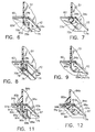
- means for securing the distal ends 70a,70b of the stakes 65a,65b against a second surface 74 of the baseplate 12 so that the stakes cannot be withdrawn from the openings 24a,24b comprise the distal ends being deformed or, more specifically, forming heads 72a,72b (although not shown, all of the distal ends of all of the stakes form heads), securing the module cover 38 to the baseplate 12 .
- a method of attaching the module cover 38 to the baseplate 12 includes: inserting the stakes 62a-62e of the first attachment leg 48 through the first set of openings 18a-18e, inserting the stakes 63a-63e of the second attachment leg 49 through the second set of openings 20a-20e , inserting the stakes 64a-64c of the third attachment leg 50 through the third set of openings 22a-22c, and inserting the stakes 65a-65c of the fourth attachment leg 51 through the fourth set of openings 24a-24c until the bottom edges 53-56 of the four attachment legs butt against the first surface 60 of the baseplate 12.
- the distal ends 67a-67e, 68a-68e, 69a-69c, 70a-70c of the stakes 62a-62e, 63a-63e, 64a-64c, 65a-65c are then secured against the second surface 74 of the baseplate 12 such that the stakes cannot be withdrawn from the openings 18a-18e,20a-20e,22a-22c,24a-24c, securing the module cover 38 to the baseplate 12 .
- the distal ends 70a,70b of the stakes 65a,65b are formed generally into heads 72a,72b (although not shown, all of the distal ends of all of the stakes are formed into heads) utilizing any suitable thermal forming process such as ultrasonic or induction welding or thermo pneumatic processes, for example.
- the heads 72a,72b preferably butt against the second surface 74 of the baseplate 12 to provide a tight, shake-and rattle-free attachment.
- the heads 72a,72b shown in FIG. 7 are idealized and the heads actually formed may be somewhat different in shape, as long as the heads are wider and/or longer and generally larger than the openings 18a-18e,20a-20e,22a-22c,24a-24c so that the heads cannot fit through the openings.
- the attachment legs 48-51 and the stakes 62a-62e, 63a-63e, 64a-64c, 65a-65c extending therefrom provide the benefit of being relatively simple to mold unitary with the lid 40 to form the module cover 38 .
- the distal ends 70a,70b of the stakes 65a,65b can alternatively be secured by being fused to a channel section 76 having a slot 78 that fits over the distal ends.
- a channel section 76 having a slot 78 that fits over the distal ends.
- three other channel sections similar to channel section 76 , are provided for mating with the stakes 62a-62e,63a-63e,64a-64c of the other three attachment legs 48,49,50, and, if desired, the four channel sections can be provided as a single unitary, channel generally forming a rectangle.
- the slot 78 of the channel section 76 is simply slipped over the distal ends 70a,70b of the stakes 65a,65b until the channel section preferably butts against the second surface 74 of the baseplate 12 and a suitable thermal forming process such as induction welding is used to fuse the distal ends to the channel to secure the module cover 38 to the baseplate 12 .
- a suitable thermal forming process such as induction welding is used to fuse the distal ends to the channel to secure the module cover 38 to the baseplate 12 .
- the distal ends 70a,70b can be attached to the channel section 76 in another suitable manner such as with an adhesive, for example.
- the channel sections provide the benefit of added strength to the attachment between the stakes and the baseplate 12 without changing the simple design of the module cover 38 .
- the stakes of the four attachment legs which are provided in an end-to-end or "in series" configuration, can alternatively be secured by joining the distal ends of adjacent pairs of the stakes 65a,65b to form a bridge 80 as shown in FIG. 9 . (Although not shown, all of the stakes or only some of the stakes may be secured by bridging.)
- the distal ends of the stakes 65a,65b are joined by a suitable thermal forming process to form the bridge 80. Bridging between the stakes provides the benefit of added strength to the attachment between the module cover 38 and the baseplate 12 without changing the simple design of the module cover.
- FIG. 10 another airbag module 82 according to the present invention is provided.
- the airbag module 82 of FIGS. 10-12 is similar to the airbag module 10 of FIGS. 1-9 and elements of the airbag module 82 that are the same as elements of the airbag module 10 have the same reference numerals.
- the airbag module 82 has a third attachment leg 84a and a fourth attachment leg 84b extending from the lid 40 of a module cover 83 and terminating at bottom edges 85a,85b butting against the first surface 60 of a baseplate 87 .
- the third and fourth attachment legs 84a,84b each have a tapering outwardly portion 95a, 95b leading to the bottom edges 85a,85b so that the bottom edges are wider than the bottom edges 55,56 of the third and the fourth attachment legs 50,51 of the airbag module 10 of FIG. 1 .
- a side-by-side or "parallel" pair of stakes 99a, 99b extends from the bottom edge 85a of the third attachment leg 84a to distal ends 97a,97b .
- the baseplate 87 defines a third set of side-by-side openings 86a,86b for receiving the pair of stakes 99a,99b of the third attachment leg 84a .
- a total of three pairs of stakes extend from the third attachment leg 84a , and side-by-side pairs of stakes can extend from the each of the first and second attachment legs 48,49 .
- four distal ends 88a,88b and 89a,89b of two pairs of side-by-side stakes 90a,90b and 91a,91b of the fourth attachment leg 84b extend through two pairs of side-by-side openings 93a,93b and 94a,94b of a fourth set of openings defined by the baseplate 87 .
- each pair of stakes 90a,90b and 91a,91b are secured by being joined by a suitable thermal forming process to form bridges 96 and 97 .
- the bridges 96 and 97 between the pairs of side-by-side stakes 90a,90b and 91a,91b provide greater strength to the attachment between the module cover 83 and the baseplate 87 than the bridge 80 between the pairs of end-to-end stakes 65a,65b of FIG. 9 , but the side-by-side stake design increases the complexity of the module cover injection molding process.
- the bridges shown in FIGS. 9 and 12 are idealized and the bridges actually formed may be somewhat different in shape, as long as the distal ends of the stakes are joined so that the stakes cannot be withdrawn from the openings.
- the bridges butt against the second surface 74 of the baseplate 12 .
- the airbag module 110 comprises a module housing 112 including a trough-shaped reaction canister 114 having a first sidewall 116a and a second sidewall 116b defining opposing ends closed by a first endplate 118a and a second endplate 118b , the reaction canister and endplates defining a mouth 120 of the module housing.
- a first flange 122 extends generally perpendicularly outwardly from the first sidewall 116a of the reaction canister 114 , spaced-apart from the mouth 120 of the module housing 112 , and defines a first set of three openings 123a-123c .
- a second flange 125 extends generally perpendicularly outwardly from the second sidewall 116b , spaced-apart from the mouth of the module housing, and defines a second set of three openings 126a-126c.
- a third flange 128 extends generally perpendicularly outwardly from the first endplate 118a , spaced-apart from the mouth of the module housing, and defines a third set of four openings 129a -129d.
- a fourth flange 131 extends generally perpendicularly outwardly from the second endplate 118b , spaced-apart from the mouth of the module housing, and defines a fourth set of four openings 132a-132d .
- the flanges 122,125,128,131 have first surfaces (not shown but facing the module cover 138 ) and second surfaces 170a-170d opposite the first surfaces.
- a folded, inflatable airbag cushion 134 and an airbag inflator (an end 136 of the inflator is shown) are secured within the reaction canister 114 between the endplates 118a,118b .
- the inflator, the airbag cushion 134 and how the inflator and airbag cushion are secured in the reaction canister 114 are known in the art and, therefore, not described here in detail.
- the airbag module 110 also includes a thermoplastic module cover 138 including a lid 140 .
- the lid 140 has a decorative outer surface 142 and an inner surface 144 , and is positioned over the folded airbag cushion 134 and the mouth 120 of the module housing 112 .
- a first attachment leg 148 and a second attachment leg 149 are unitary with and extend from the inner surface 144 of the lid 140 and terminate at bottom edges 153,154 .
- the first and the second attachment legs 148,149 are in spaced, opposing relationship in alignment with the first and the second sets of openings 123a-123c,126a-126c defined by the module housing 112 .
- a third attachment leg 150 and a fourth attachment leg 151 are unitary with and extend from the lid 140 and terminate at bottom edges 155,156 .
- the third and the fourth attachment legs 150,151 are in spaced, opposing relationship in alignment with the third and the fourth sets of openings 129a-129d,132a-132d defined by the module housing 112.
- the bottom edges 153-156 of the four attachment legs 148-151 butt, respectively, against the first surfaces of the four flanges 122,125,128,131 extending from the module housing 112 , and in alignment with the four sets of openings 123a-123c,126a-126c, 129a-129d,132a-132d defined by the four flanges.
- the four attachment legs 148-151 space the lid 140 away from the mouth 120 of the module housing 112 and generally form a rectangle surrounding the folded airbag cushion 134 and the mouth.
- the four attachment legs 148-151, the lid 140 and the module housing 112 substantially contain and protect the folded airbag cushion 134 .
- the four, separate attachment legs 148-151 could be unitary in the form of a single, continuous attachment wall defining a rectangle or another suitable shape such as circle, for example.
- the module cover 138 could have more or less than four attachment legs with the module housing 112 defining a similar number of sets of openings, as long as the module cover has at least two spaced, opposed attachment legs.
- Three spaced-apart stakes 158a-158c are unitary with and extend from the bottom edge 153 of the first attachment leg 148 to distal ends 163a-163c, and three spaced-apart stakes 159a-159c are unitary with and extend from the bottom edge 154 of the second attachment leg 149 to distal ends 164a-164c .
- Four spaced-apart stakes 160a-160d are unitary with and extend from the bottom edge 155 of the third attachment leg 150 to distal ends 165a-165d, and four spaced-apart stakes 161a-161d are unitary with and extend from the bottom edge 156 of the fourth attachment leg 151 to distal ends 166a-166d .
- the number of stakes extending from the attachment legs and the number of openings in the sets of openings can be suitably increased or decreased.
- each of the stakes 158a-158c of the first attachment leg 148 extends through one of the openings of the first set of openings 123a-123c
- each of the stakes 159a-159c of the second attachment leg 149 extends through one of the openings of the second set of openings 126a-126c
- each of the stakes 160a-160d of the third attachment leg 150 extends through one of the openings of the third set of openings 129a-129d
- each of the stakes 161a-161d of the fourth attachment leg 151 extends through one of the openings of the fourth set of openings 132a-132d .
- the distal ends 163a-163c,164a-164c,165a-165d,166a-166d of all the stakes 158a-158c,159a-159c,160a-160d,161a-161d are secured against the second surfaces 170a-170b of the flanges 122, 125,128,131 such that the stakes cannot be withdrawn from the openings 123a-123c,126a-126c,129a-129d,132a-132d defined by the flanges, securing the module cover 138 to the module housing 112 .
- the distal ends of the stakes 158a-158c of the first attachment leg 148 form heads 168a-168c and the distal ends of the stakes 159a-159c of the third attachment leg 150 form heads 169a-169d (the heads of the second and the fourth attachment legs are not shown but are similar).
- the distal ends are formed into heads by a suitable thermal forming process such as ultrasonic welding, for example.
- the heads butt against the second surfaces 170a-170b of the flanges 122,125, 128,131 .
- the module cover 138 also includes three tear seams 146a,146b defined by the first, the third and the fourth attachment legs 148,150,151 (the third tear seam is not shown but is similar to tear seam 146a ).
- the tear seams 146a,146b run parallel with the lid 140 and preferably are positioned where the attachment legs join the lid. Alternatively, the lid can define at least one tear seam.
- the present invention therefore, provides a novel, simple and effective module cover attachment and a method of attaching a module cover to an airbag module. Since other changes and modifications varied to fit particular operating requirements and environments will be apparent to those skilled in the art, the invention is not considered limited to the examples chosen for purposes of illustration, and includes all changes and modifications which do not constitute a departure from the true scope of this invention as claimed in the following claims.
Landscapes
- Engineering & Computer Science (AREA)
- Mechanical Engineering (AREA)
- Air Bags (AREA)
Applications Claiming Priority (2)
| Application Number | Priority Date | Filing Date | Title |
|---|---|---|---|
| US656404 | 1996-05-31 | ||
| US08/656,404 US5741024A (en) | 1996-05-31 | 1996-05-31 | Airbag module cover attachment and method of attaching a module cover to an airbag module |
Publications (2)
| Publication Number | Publication Date |
|---|---|
| EP0810127A2 true EP0810127A2 (de) | 1997-12-03 |
| EP0810127A3 EP0810127A3 (de) | 1998-07-08 |
Family
ID=24632906
Family Applications (1)
| Application Number | Title | Priority Date | Filing Date |
|---|---|---|---|
| EP97303652A Withdrawn EP0810127A3 (de) | 1996-05-31 | 1997-05-29 | Abdeckungsbefestigung für ein Airbagmodul und Verfahren zur Befestigung einer Abdeckung an einem Airbagmodul |
Country Status (3)
| Country | Link |
|---|---|
| US (1) | US5741024A (de) |
| EP (1) | EP0810127A3 (de) |
| JP (1) | JP2899574B2 (de) |
Cited By (1)
| Publication number | Priority date | Publication date | Assignee | Title |
|---|---|---|---|---|
| WO2006022969A1 (en) * | 2004-08-20 | 2006-03-02 | Key Safety Systems, Inc | Connector for attaching the cover to housing of an airbag module |
Families Citing this family (19)
| Publication number | Priority date | Publication date | Assignee | Title |
|---|---|---|---|---|
| DE29616891U1 (de) * | 1996-09-27 | 1997-01-30 | Trw Occupant Restraint Systems Gmbh, 73551 Alfdorf | Einrichtung zum Befestigen eines Gassackmoduls |
| JP3793790B2 (ja) * | 1997-04-11 | 2006-07-05 | カルソニックカンセイ株式会社 | 車両用エアバッグ装置 |
| WO1999046151A1 (en) * | 1998-03-11 | 1999-09-16 | Breed Automotive Technology, Inc. | Attachment of airbag to housing |
| JP4734702B2 (ja) * | 2000-02-29 | 2011-07-27 | タカタ株式会社 | エアバッグ装置のカバー体の製造方法及びカバー体本体 |
| EP1151898B1 (de) | 2000-04-28 | 2004-02-25 | Inoac Corporation | Reisstruktur einer Luftsackabdeckung |
| US20030205890A1 (en) * | 2002-05-06 | 2003-11-06 | Lear Corporation | Air bag containment apparatus |
| US20040041370A1 (en) * | 2002-08-30 | 2004-03-04 | Lear Corporation | Slide attachment for air bag canister to instrument panel |
| US20050104338A1 (en) * | 2003-11-19 | 2005-05-19 | Quin Soderquist | Applique film airbag cover |
| US20080100040A1 (en) * | 2006-10-27 | 2008-05-01 | Autoliv Asp, Inc. | Airbag cover retention method |
| DE102007011109A1 (de) * | 2007-03-05 | 2008-09-11 | Takata-Petri Ag | Folienplakette für eine Airbagabdeckung |
| DE102009008383B4 (de) * | 2009-02-11 | 2016-09-22 | Autoliv Development Ab | Befestigungsanordnung |
| DE102009030149B3 (de) | 2009-06-19 | 2010-12-30 | Takata-Petri Ag | Gassackmodul für ein Fahrzeuginsassen-Rückhaltesystem |
| DE102009030151B3 (de) * | 2009-06-19 | 2010-12-09 | Takata-Petri Ag | Gassackmodul für ein Fahrzeuginsassen-Rückhaltesystem |
| US8944460B2 (en) * | 2011-06-30 | 2015-02-03 | Ford Global Technologies, Llc | Air bag chute topper system |
| JP5790311B2 (ja) * | 2011-08-24 | 2015-10-07 | タカタ株式会社 | 運転席用エアバッグ装置の取付構造及びステアリングホイール |
| JP6215646B2 (ja) * | 2013-10-22 | 2017-10-18 | 株式会社ダイセル | インフレータとエアバッグの固定構造 |
| JP6492370B2 (ja) * | 2016-03-15 | 2019-04-03 | 本田技研工業株式会社 | エアバッグ装置 |
| USD1109940S1 (en) | 2022-01-10 | 2026-01-20 | Old Dog New Tricks | Bowl for pet and human foodstuff and drinkable liquids |
| USD1109939S1 (en) | 2022-01-10 | 2026-01-20 | Old Dog New Tricks LLC | Bowl for pet and human foodstuff and drinkable liquids |
Family Cites Families (13)
| Publication number | Priority date | Publication date | Assignee | Title |
|---|---|---|---|---|
| US4895389A (en) * | 1988-08-31 | 1990-01-23 | E. I. Dupont De Nemours And Company | Rupturable cover for a vehicle air bag compartment |
| US4941678A (en) * | 1989-06-29 | 1990-07-17 | Morton Thiokol, Inc. | Lightweight reaction can for passenger inflators |
| JPH05262198A (ja) * | 1992-03-17 | 1993-10-12 | Takata Kk | 助手席用エアバッグ装置のリッド |
| US5280946A (en) * | 1992-06-01 | 1994-01-25 | Morton International, Inc. | Cover for air bag installation |
| US5354093A (en) * | 1993-04-05 | 1994-10-11 | General Motors Corporation | Air bag module having integral cover attachment |
| US5409256A (en) * | 1994-01-04 | 1995-04-25 | General Motors Corporation | Driver-side air bag module assembly |
| FR2715902B1 (fr) * | 1994-02-04 | 1996-04-26 | Ecia Equip Composants Ind Auto | Dispositif de fixation d'un couvercle de module à sac gonflable sur un organe de support de celui-ci. |
| US5435596A (en) * | 1994-05-09 | 1995-07-25 | Morton International, Inc. | Passenger airbag module deployment door attachment system |
| US5460400A (en) * | 1994-05-20 | 1995-10-24 | Takata, Inc. | Passenger-side air bag module with improved assembly features |
| DE4434685A1 (de) * | 1994-07-19 | 1996-04-04 | Takata Europ Gmbh | Airbag-Anordnung |
| US5658008A (en) * | 1994-07-19 | 1997-08-19 | Takata (Europe) Vehicle Safety Technology Gmbh | Airbag arrangement |
| US5490689A (en) * | 1995-01-05 | 1996-02-13 | Morton International, Inc. | Reaction can to cover joining method |
| US5523532A (en) * | 1995-02-06 | 1996-06-04 | Morton International, Inc. | Airbag module cover with attached horn switch and method of producing same |
-
1996
- 1996-05-31 US US08/656,404 patent/US5741024A/en not_active Expired - Fee Related
-
1997
- 1997-05-28 JP JP9138489A patent/JP2899574B2/ja not_active Expired - Fee Related
- 1997-05-29 EP EP97303652A patent/EP0810127A3/de not_active Withdrawn
Cited By (2)
| Publication number | Priority date | Publication date | Assignee | Title |
|---|---|---|---|---|
| WO2006022969A1 (en) * | 2004-08-20 | 2006-03-02 | Key Safety Systems, Inc | Connector for attaching the cover to housing of an airbag module |
| US7216892B2 (en) | 2004-08-20 | 2007-05-15 | Key Safety Systems, Inc. | Air bag door and attachment method |
Also Published As
| Publication number | Publication date |
|---|---|
| JPH1053083A (ja) | 1998-02-24 |
| EP0810127A3 (de) | 1998-07-08 |
| JP2899574B2 (ja) | 1999-06-02 |
| US5741024A (en) | 1998-04-21 |
Similar Documents
| Publication | Publication Date | Title |
|---|---|---|
| EP0810127A2 (de) | Abdeckungsbefestigung für ein Airbagmodul und Verfahren zur Befestigung einer Abdeckung an einem Airbagmodul | |
| US5096222A (en) | Vehicle air bag module and method of assembly | |
| CN1042016C (zh) | 车辆气袋制约系统 | |
| US5647608A (en) | Air bag module with extruded housing | |
| EP0698532B1 (de) | Mit verschliessbarer Endkappe in einem Diffusionsgehäuse einer Airbageinheit gesicherte Aufblaseinheit | |
| US6029992A (en) | Air bag module and steering wheel assembly | |
| US7175195B2 (en) | Occupant protection device | |
| US7125043B2 (en) | Airbag device | |
| EP0582443B1 (de) | Air-Bag-Abdeckung für Hochleistungs-Gasgenerator und Scharnier dafür | |
| US5433471A (en) | Simplified passenger air bag module | |
| US5810390A (en) | Module case for side impact airbag module | |
| EP0602785A2 (de) | Diffusorvorrichtung und deren Einbau in ein aufblasbares Rückhaltesystem | |
| US6942244B2 (en) | Cover and housing structure for an airbag module | |
| EP0816182B1 (de) | Luftsackaufblasvorrichtung mit Haltestreifen | |
| CA2018045A1 (en) | Lightweight reaction can for passenger inflators | |
| GB2420750A (en) | Vehicle seat with arrangement for holding an airbag deployment seam in position. | |
| US6902186B2 (en) | Knee protecting airbag device | |
| JPWO1998019894A1 (ja) | サイドエアバッグ装置のエアバッグ | |
| JP3045705U (ja) | モジュールカバー及びモジュールハウジング並びにエアバッグモジュール | |
| EP0834430A1 (de) | Seitenaufprall- Luftsackmodul mit einer Kombinationaufblasvorrichtung und Modulgehäuse | |
| GB2423965A (en) | Vehicle seat with means for retaining airbag deployment seam in position | |
| GB2420752A (en) | Vehicle seat with guide facilitating deployment of built-in airbag | |
| CA2038140A1 (en) | Occupant restraint system | |
| EP0680852A2 (de) | Bandverankerte, befestigungsmittelfreie Entfaltungsklappe für Insassen-Seiten-Airbagmodul | |
| US5378013A (en) | Cover retainer assembly for inflatable restraint air bag |
Legal Events
| Date | Code | Title | Description |
|---|---|---|---|
| PUAI | Public reference made under article 153(3) epc to a published international application that has entered the european phase |
Free format text: ORIGINAL CODE: 0009012 |
|
| AK | Designated contracting states |
Kind code of ref document: A2 Designated state(s): DE FR GB IT |
|
| PUAL | Search report despatched |
Free format text: ORIGINAL CODE: 0009013 |
|
| AK | Designated contracting states |
Kind code of ref document: A3 Designated state(s): DE FR GB IT |
|
| STAA | Information on the status of an ep patent application or granted ep patent |
Free format text: STATUS: THE APPLICATION IS DEEMED TO BE WITHDRAWN |
|
| 18D | Application deemed to be withdrawn |
Effective date: 19990109 |