EP0810312A1 - Métier à tisser, en particulier métier multiphase - Google Patents
Métier à tisser, en particulier métier multiphase Download PDFInfo
- Publication number
- EP0810312A1 EP0810312A1 EP96810348A EP96810348A EP0810312A1 EP 0810312 A1 EP0810312 A1 EP 0810312A1 EP 96810348 A EP96810348 A EP 96810348A EP 96810348 A EP96810348 A EP 96810348A EP 0810312 A1 EP0810312 A1 EP 0810312A1
- Authority
- EP
- European Patent Office
- Prior art keywords
- waste
- container
- weaving
- transport
- transport device
- Prior art date
- Legal status (The legal status is an assumption and is not a legal conclusion. Google has not performed a legal analysis and makes no representation as to the accuracy of the status listed.)
- Granted
Links
- 239000000463 material Substances 0.000 claims abstract description 11
- 230000005484 gravity Effects 0.000 claims abstract description 8
- 239000002699 waste material Substances 0.000 claims description 49
- 238000009941 weaving Methods 0.000 claims description 46
- 239000000872 buffer Substances 0.000 claims description 9
- 230000009471 action Effects 0.000 claims description 2
- 238000000034 method Methods 0.000 claims description 2
- 239000007787 solid Substances 0.000 claims 3
- 230000000903 blocking effect Effects 0.000 claims 1
- 238000005192 partition Methods 0.000 claims 1
- 239000004744 fabric Substances 0.000 abstract description 5
- 238000005096 rolling process Methods 0.000 abstract 1
- 230000008901 benefit Effects 0.000 description 4
- 229920000742 Cotton Polymers 0.000 description 3
- 239000013590 bulk material Substances 0.000 description 3
- 229920002994 synthetic fiber Polymers 0.000 description 2
- 230000007704 transition Effects 0.000 description 2
- 206010067482 No adverse event Diseases 0.000 description 1
- 230000008859 change Effects 0.000 description 1
- 210000001520 comb Anatomy 0.000 description 1
- 230000002950 deficient Effects 0.000 description 1
- 230000003993 interaction Effects 0.000 description 1
- 230000007257 malfunction Effects 0.000 description 1
- 230000000737 periodic effect Effects 0.000 description 1
- 230000008569 process Effects 0.000 description 1
- 230000008439 repair process Effects 0.000 description 1
- 238000012958 reprocessing Methods 0.000 description 1
- 238000000926 separation method Methods 0.000 description 1
- 230000001960 triggered effect Effects 0.000 description 1
- 238000004804 winding Methods 0.000 description 1
Images
Classifications
-
- D—TEXTILES; PAPER
- D03—WEAVING
- D03D—WOVEN FABRICS; METHODS OF WEAVING; LOOMS
- D03D47/00—Looms in which bulk supply of weft does not pass through shed, e.g. shuttleless looms, gripper shuttle looms, dummy shuttle looms
- D03D47/40—Forming selvedges
-
- D—TEXTILES; PAPER
- D03—WEAVING
- D03J—AUXILIARY WEAVING APPARATUS; WEAVERS' TOOLS; SHUTTLES
- D03J1/00—Auxiliary apparatus combined with or associated with looms
- D03J1/002—Climatic conditioning or removing lint or dust
Definitions
- the invention relates to a weaving machine, in particular a row shed weaving machine with a selvedge cutting device that generates a waste edge, which is drawn off as a band from a pull-off device and is deposited in a container A under the action of gravity.
- the object of the present invention is to create a reliable system for waste disposal on weaving machines, in particular on row shed weaving machines. This object is achieved with the features of independent claims 1, 3 and 9.
- the advantages of the invention lie in the fact that the waste from a plurality of weaving machines can be stored centrally, and depending on the material of the waste it can be fed into different or identical collecting lines. Because, for example, flight and weft remnants on the one hand and waste with warp thread material on the other hand are first brought separately into a form suitable for batch air transport and these batches are brought to the same or different collecting lines via stationary transport devices, each article change on the weaving machine can be carried out with little effort optimal disposal can be preset. Waste edges and any excess warp threads with synthetic material can be disposed of separately from flight and cotton weft remnants. No personnel are required on the weaving machine for disposal.
- Waste for articles with only cotton waste can also be led to a collecting line "for cotton waste” and for articles with synthetic material in warp and weft threads to a collecting line "for synthetic waste”. If, in such a context, the reprocessing of material from a central waste bunker is considered and the separation of the admixed flight proves to be too complex, the flight can also be suctioned off separately on the weaving machine and from a separate container B into one Collecting line can be removed. This concept enables cost-effective full automation of waste disposal from the weaving machine to a central waste bunker.
- an intermediate store A By shredding endless tapes and warp threads, an intermediate store A can be created, from which smaller batches are fed into a collecting line at regular intervals via a stationary transport device. Due to the time interval, the batch size can be chosen so small that the manifold does not have to be too large. If the transport devices on different weaving machines are networked with one another in their control system, this can be designed such that only one transport device can feed into a bus at a time and that the other transport devices are connected in a queue in order not to make the bus line so large with its air flow to have to.
- the sensors and actuators of the device are integrated into the weaving machine control, e.g. the central collection system receives its own control by generating its own air flow in the manifolds.
- the separate module its own control, which is linked to the machine control or a central control.
- the connection to a central control is unproblematic insofar as the module can also be clocked "blindly", since it can carry out its function regardless of whether the weaving machine in question is standing or in operation, i.e. can carry out an ejection.
- a drive unit for the switch can be integrated into both the machine control and the control of the module in order to make the switch adjustment possible via a control input.
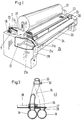
- FIG. 1 shows a row shed weaving machine 25 which has side frames 28, 28 ', between which the non-visible warp beam, the warp threads 24, the cloth 23 and the fabric beam 22 with winding device 27 are arranged.
- the actual weaving process takes place on a weaving rotor, which is arranged under a cover 26, in that the warp threads lying around a partial circumference on the weaving rotor are combed as compartments by combs of the weaving rotor and weft threads are shot into the compartments during combing. The wefts are struck at the exit of the warp threads from the weaving rotor and thus form the cloth 23.
- the selvedges are trimmed on both sides of the cloth 23 and there are waste edges in the form of strips 1, 2, which are drawn off via deflections 20 by a pull-off device 3 which has two corrugated rollers 18 rotating against one another under contact pressure. Excess warp threads 14 are also fed to the puller 3. With a suction pipe 21 in a branch 21a the flight under the cover 26, in a branch 21b the weft tips at Weft arrival and defective weft threads are sucked into a branch 21c during the weft break repair, a suction fan 4 (see FIG. 2) having to be present in order to generate the necessary negative pressure in the suction pipe 21.
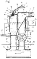
- a container A is arranged below the puller 3, in which the tapes 1, 2 and excess warp threads 14 are fed via a funnel 17.
- a cutting device 6 with a drive 6 ', which is controlled by a controller 15 in such a way that excess warp threads 14 and ribbons 1, 2 are cut into sections 7 of about 10 cm in length and are in bulk at the bottom of the Collect container A.
- Container A and cutting device 6 are covered by a lid 19.
- the bottom is at the same time in the form of a slide with a drive 8 'part of a transport device 8, which has an inlet pipe 33 behind the slide in order to feed the bulk material in batches to a collecting line 11 under the influence of gravity.
- An air flow 12 flows through the collecting line 11, which carries the bulk material to a central waste bunker.
- the drive 8 ′ of the transport device 8 is clocked by the controller 15 such that the batches of bulk material are small enough to be carried along by the air flow 12.
- a sensor 16, which is also connected to the controller 15, monitors the fill level in the container A in order to indicate and alert any congestion.
- FIG. 2 also shows a container B into which the intake pipe 21 (see FIG. 1) opens.
- the container B is closed at the top by a sieve, to which a suction blower 4 with a drive 4 ′ connects in order to increase the necessary permanent flow in the intake pipe 21 produce.
- the fan 4 sucks an air stream from a dirty air stream 31 through a filter 5 in the container B, which air stream enters the blower 4 as a cleaned air stream 32.
- Flight 10 and remnants of weft thread arrive as contaminated flow 31 in container B and are deposited on the container bottom, which is formed by a transport device 9 in the form of an impeller with chambers 13.
- the impeller forms a lock with the chambers 13, which makes the pressure in the container B independent of the pressure in the manifold 11. If one dispenses with a transport device 9 in the form of a lock and only uses a shut-off device analogous to container A, one has to be sure that the brief opening to the collecting line 11 has no adverse effects on the suction on the weaving machine.
- the manifold is laid in a channel 29 below the base 30 for the weaving machines.
- the inlet pipes 33, 34 from the containers A, B are connected by flanges with sockets on the manifold 11, the sockets having a curved inlet 39 to the manifold 11. This has the advantage that no material can get caught in the manifold during the transition.
- transitions have the advantage that with an air flow 12 with a high speed component the dynamic pressure may be higher than atmospheric pressure in the manifold without backflow into inlet pipes 33 at atmospheric pressure.
- the manifold 11 then acts more like a jet pump that sucks material from the inlet pipes 33, 34. For transport in the collecting lines and for pressure losses on the way, larger pressure differences can therefore be used than if only one suction fan was installed at the central collecting point.
- the suction fan 4 on the loom is connected to the controller 15 of the module via its drive 4 '. However, it could also be coupled directly to the operation of the weaving machine via the machine control, since the actuation by the transport device 9, 9 'may be triggered independently of the operation of the weaving machine.
- a switch 40 is shown, which is mounted between the inlet pipe 33, 34 and various manifolds 11 to feed into one or the other manifold 11 depending on the composition of the material of an article.
- a flexible hose 35 with a hose clamp 36 is connected to the inlet pipe 33 and fixed on a flat slide 37 at the other end.
- the attachment is also done with a hose clip on a pipe section, which simultaneously forms an opening on the flat slide 37.
- the flat slide 37 can now be brought with a stroke 38 over the inlet 39 of the left or right manifold 11 in order to guide weft remnants with flight 10 and warp thread material 1, 2, 14 to the appropriate manifold depending on the material composition.
- Similar switches can also be used in a central bunker for a collecting line in order to feed individual waste batches according to their composition to different waste containers.
Landscapes
- Engineering & Computer Science (AREA)
- Textile Engineering (AREA)
- Looms (AREA)
- Auxiliary Weaving Apparatuses, Weavers' Tools, And Shuttles (AREA)
Priority Applications (3)
| Application Number | Priority Date | Filing Date | Title |
|---|---|---|---|
| EP19960810348 EP0810312B1 (fr) | 1996-05-31 | 1996-05-31 | Métier à tisser, en particulier métier multiphase |
| DE59607833T DE59607833D1 (de) | 1996-05-31 | 1996-05-31 | Webmaschine, insbesondere Reihenfachwebmaschine |
| JP7974297A JPH1018148A (ja) | 1996-05-31 | 1997-03-31 | 経糸開口直列配置型織機 |
Applications Claiming Priority (1)
| Application Number | Priority Date | Filing Date | Title |
|---|---|---|---|
| EP19960810348 EP0810312B1 (fr) | 1996-05-31 | 1996-05-31 | Métier à tisser, en particulier métier multiphase |
Publications (2)
| Publication Number | Publication Date |
|---|---|
| EP0810312A1 true EP0810312A1 (fr) | 1997-12-03 |
| EP0810312B1 EP0810312B1 (fr) | 2001-10-04 |
Family
ID=8225621
Family Applications (1)
| Application Number | Title | Priority Date | Filing Date |
|---|---|---|---|
| EP19960810348 Expired - Lifetime EP0810312B1 (fr) | 1996-05-31 | 1996-05-31 | Métier à tisser, en particulier métier multiphase |
Country Status (3)
| Country | Link |
|---|---|
| EP (1) | EP0810312B1 (fr) |
| JP (1) | JPH1018148A (fr) |
| DE (1) | DE59607833D1 (fr) |
Families Citing this family (1)
| Publication number | Priority date | Publication date | Assignee | Title |
|---|---|---|---|---|
| CN111058161A (zh) * | 2019-12-26 | 2020-04-24 | 浙江锐盈电子科技有限公司 | 一种纺织生产用具有灰尘检测功能的纺织尘收集装置 |
Citations (7)
| Publication number | Priority date | Publication date | Assignee | Title |
|---|---|---|---|---|
| US3311135A (en) * | 1965-06-24 | 1967-03-28 | Grinnell Corp | Lint collecting enclosure |
| GB2021161A (en) * | 1978-05-17 | 1979-11-28 | Rossville Mills Inc | Shuttleless looms |
| US4513791A (en) * | 1983-02-01 | 1985-04-30 | Burlington Industries, Inc. | Leno selvaging and stretch nozzle system |
| EP0408376A1 (fr) * | 1989-07-12 | 1991-01-16 | Luwa Japan Limited | Dispositif pour nettoyer les métiers à tisser |
| DE3942156A1 (de) * | 1989-12-20 | 1991-07-04 | Zinser Textilmaschinen Gmbh | Reinigungsvorrichtung im bereich einer spinnereimaschine |
| JPH0641849A (ja) * | 1992-07-16 | 1994-02-15 | Tsudakoma Corp | 糸端処理糸の回収装置 |
| JPH0641850A (ja) * | 1992-07-16 | 1994-02-15 | Tsudakoma Corp | 糸端処理糸の排出方法および排出装置 |
-
1996
- 1996-05-31 EP EP19960810348 patent/EP0810312B1/fr not_active Expired - Lifetime
- 1996-05-31 DE DE59607833T patent/DE59607833D1/de not_active Expired - Fee Related
-
1997
- 1997-03-31 JP JP7974297A patent/JPH1018148A/ja not_active Withdrawn
Patent Citations (7)
| Publication number | Priority date | Publication date | Assignee | Title |
|---|---|---|---|---|
| US3311135A (en) * | 1965-06-24 | 1967-03-28 | Grinnell Corp | Lint collecting enclosure |
| GB2021161A (en) * | 1978-05-17 | 1979-11-28 | Rossville Mills Inc | Shuttleless looms |
| US4513791A (en) * | 1983-02-01 | 1985-04-30 | Burlington Industries, Inc. | Leno selvaging and stretch nozzle system |
| EP0408376A1 (fr) * | 1989-07-12 | 1991-01-16 | Luwa Japan Limited | Dispositif pour nettoyer les métiers à tisser |
| DE3942156A1 (de) * | 1989-12-20 | 1991-07-04 | Zinser Textilmaschinen Gmbh | Reinigungsvorrichtung im bereich einer spinnereimaschine |
| JPH0641849A (ja) * | 1992-07-16 | 1994-02-15 | Tsudakoma Corp | 糸端処理糸の回収装置 |
| JPH0641850A (ja) * | 1992-07-16 | 1994-02-15 | Tsudakoma Corp | 糸端処理糸の排出方法および排出装置 |
Non-Patent Citations (1)
| Title |
|---|
| PATENT ABSTRACTS OF JAPAN vol. 018, no. 271 (C - 1203) 24 May 1994 (1994-05-24) * |
Also Published As
| Publication number | Publication date |
|---|---|
| DE59607833D1 (de) | 2001-11-08 |
| JPH1018148A (ja) | 1998-01-20 |
| EP0810312B1 (fr) | 2001-10-04 |
Similar Documents
| Publication | Publication Date | Title |
|---|---|---|
| DE1510381C3 (de) | Vorrichtung zur Abscheidung von aus Spinnereimaschinen, insbesondere Karden, abgesaugtem Faserflug | |
| DE4231330A1 (de) | Bahnzuschneidvorrichtung | |
| DE69813518T2 (de) | Vorrichtung zur herstellung von fasern | |
| DE4229552C2 (de) | Textilmaschine mit einer Absaugeinrichtung mit einer Abscheidekammer | |
| EP2284302B1 (fr) | Métier à filer continu | |
| DE2430347A1 (de) | Luftreinigungsanordnung und -verfahren | |
| DE2855311C2 (de) | Vorrichtung zur Verarbeitung von Textilfasergut | |
| DE1510222A1 (de) | Faserzufuehrungsvorrichtung | |
| EP1360351B2 (fr) | Dispositif pour eliminer des impuretes | |
| EP0810312B1 (fr) | Métier à tisser, en particulier métier multiphase | |
| EP0692200B1 (fr) | Procédé et dispositif pour le dépoussiérage et le refroidissement de l'air d'échappement dans une machine de fabrication de cigarettes | |
| DE2158338C3 (de) | Verfahren und Einrichtung zum Reinigen von Filterzellen | |
| EP0535501A2 (fr) | Installation de dépoussiérage pour machines | |
| DE4021174C2 (de) | Anlage zum Durchlauf-Vakuum-Flüssigbeschichten | |
| CH256989A (de) | Verfahren zum Transport des durch eine Fadenbruch-Absauganlage an Spinnmaschinen abgesaugten Materials. | |
| CH676254A5 (fr) | ||
| DE2339880A1 (de) | Pneumatische reinigungsanlage der streckwerke in vorspinn- und spinnmaschinen | |
| EP0764222B1 (fr) | Element de stockage intermediaire | |
| CH691861A5 (de) | Vorrichtung zum Reinigen von Fasermaterial an einem Offenend-Spinnaggregat. | |
| CH426635A (de) | Verfahren zur pneumatischen Förderung und Verteilung von gelockertem Fasermaterial, und Vorrichtung zur Durchführung des Verfahrens | |
| EP0049857A1 (fr) | Métier à tricoter circulaire pour fabriquer un tricot pelucheux ayant des fibres insérées | |
| DE1410599A1 (de) | Verfahren zum Betrieb von Karden,Krempeln und anderen Maschinen der Spinnerei-Vorbereitung durch Entfernen von Flug und Staub um und in der Maschine und zum Austragen ausgeschiedenen Fasergutes,unterhalb des Tambourrostes und des Vorreissers anfallenden,z.B. aus Fasern bestehenden Gutes | |
| DE3891430C2 (de) | Reinigungsvorrichtung für Spinnmaschinen | |
| DE10255518A1 (de) | Krempel mit Luft-Teiler | |
| DE1254057B (de) | Einrichtung an Krempeln zum pneumatischen Entfernen des faser- und staubartigen Abfalls |
Legal Events
| Date | Code | Title | Description |
|---|---|---|---|
| PUAI | Public reference made under article 153(3) epc to a published international application that has entered the european phase |
Free format text: ORIGINAL CODE: 0009012 |
|
| AK | Designated contracting states |
Kind code of ref document: A1 Designated state(s): BE DE IT |
|
| RBV | Designated contracting states (corrected) |
Designated state(s): BE DE IT |
|
| 17P | Request for examination filed |
Effective date: 19980506 |
|
| 17Q | First examination report despatched |
Effective date: 19981207 |
|
| RAP1 | Party data changed (applicant data changed or rights of an application transferred) |
Owner name: SULZER TEXTIL AG |
|
| RAP1 | Party data changed (applicant data changed or rights of an application transferred) |
Owner name: SULZER TEXTIL AG |
|
| GRAG | Despatch of communication of intention to grant |
Free format text: ORIGINAL CODE: EPIDOS AGRA |
|
| GRAG | Despatch of communication of intention to grant |
Free format text: ORIGINAL CODE: EPIDOS AGRA |
|
| GRAH | Despatch of communication of intention to grant a patent |
Free format text: ORIGINAL CODE: EPIDOS IGRA |
|
| GRAH | Despatch of communication of intention to grant a patent |
Free format text: ORIGINAL CODE: EPIDOS IGRA |
|
| GRAA | (expected) grant |
Free format text: ORIGINAL CODE: 0009210 |
|
| AK | Designated contracting states |
Kind code of ref document: B1 Designated state(s): BE DE IT |
|
| REF | Corresponds to: |
Ref document number: 59607833 Country of ref document: DE Date of ref document: 20011108 |
|
| PLBE | No opposition filed within time limit |
Free format text: ORIGINAL CODE: 0009261 |
|
| STAA | Information on the status of an ep patent application or granted ep patent |
Free format text: STATUS: NO OPPOSITION FILED WITHIN TIME LIMIT |
|
| 26N | No opposition filed | ||
| PGFP | Annual fee paid to national office [announced via postgrant information from national office to epo] |
Ref country code: DE Payment date: 20040510 Year of fee payment: 9 |
|
| PGFP | Annual fee paid to national office [announced via postgrant information from national office to epo] |
Ref country code: BE Payment date: 20040608 Year of fee payment: 9 |
|
| PG25 | Lapsed in a contracting state [announced via postgrant information from national office to epo] |
Ref country code: IT Free format text: LAPSE BECAUSE OF NON-PAYMENT OF DUE FEES;WARNING: LAPSES OF ITALIAN PATENTS WITH EFFECTIVE DATE BEFORE 2007 MAY HAVE OCCURRED AT ANY TIME BEFORE 2007. THE CORRECT EFFECTIVE DATE MAY BE DIFFERENT FROM THE ONE RECORDED. Effective date: 20050531 Ref country code: BE Free format text: LAPSE BECAUSE OF NON-PAYMENT OF DUE FEES Effective date: 20050531 |
|
| BERE | Be: lapsed |
Owner name: *SULZER TEXTIL A.G. Effective date: 20050531 |
|
| PG25 | Lapsed in a contracting state [announced via postgrant information from national office to epo] |
Ref country code: DE Free format text: LAPSE BECAUSE OF NON-PAYMENT OF DUE FEES Effective date: 20051201 |
|
| BERE | Be: lapsed |
Owner name: *SULZER TEXTIL A.G. Effective date: 20050531 |