EP0810328A2 - Butée pour étrésillon utilisé dans le blindage des tranchées - Google Patents
Butée pour étrésillon utilisé dans le blindage des tranchées Download PDFInfo
- Publication number
- EP0810328A2 EP0810328A2 EP97108785A EP97108785A EP0810328A2 EP 0810328 A2 EP0810328 A2 EP 0810328A2 EP 97108785 A EP97108785 A EP 97108785A EP 97108785 A EP97108785 A EP 97108785A EP 0810328 A2 EP0810328 A2 EP 0810328A2
- Authority
- EP
- European Patent Office
- Prior art keywords
- pressure
- die
- stop
- support
- braking device
- Prior art date
- Legal status (The legal status is an assumption and is not a legal conclusion. Google has not performed a legal analysis and makes no representation as to the accuracy of the status listed.)
- Withdrawn
Links
Images

Classifications
-
- E—FIXED CONSTRUCTIONS
- E02—HYDRAULIC ENGINEERING; FOUNDATIONS; SOIL SHIFTING
- E02D—FOUNDATIONS; EXCAVATIONS; EMBANKMENTS; UNDERGROUND OR UNDERWATER STRUCTURES
- E02D17/00—Excavations; Bordering of excavations; Making embankments
- E02D17/06—Foundation trenches ditches or narrow shafts
- E02D17/08—Bordering or stiffening the sides of ditches trenches or narrow shafts for foundations
Definitions
- a hook-shaped stop is provided with a pivotable bolt which can be hung and locked in openings in a wall of a support.
- the openings are made at different heights so that the struts can be locked at a suitable height for the respective application.
- the row of vertically stacked openings for receiving the stops weakens the rigidity of the support, which has to absorb extremely high forces when driving into the ground and when supporting the trench walls, which are up to 7 m high.
- the insertion and locking of the stop in the openings of the support is a very tedious job, considering that a large amount of soil has to be moved when digging trenches, so that contamination and blockages of the openings for the stops can be expected.
- the installation of the openings increases the manufacturing costs of the support.
- the object of the invention is to provide a trench shoring device in which the means for fixing the struts in their vertical position is easy to handle, it not being necessary to break through a column wall.
- stop on the support is vertically displaceable and is provided with a braking device acting on the support.
- the braking device is preferably blocked by loading due to the weight of the struts acting vertically downwards on the stop and released from this weight by relieving it.
- the braking device is integrated directly into the strut as a means for fixing the strut.
- the stop is guided vertically displaceably on the support and preferably in the inner sliding guide for the struts, so that it is no longer bound to discrete adjustment heights, but can be moved as desired.
- the braking device is designed so that the necessary braking force for holding the struts is generated by the weight of the struts. A variety of constructive designs are available for this. When the brake is relieved by lifting the struts with an excavator, the brake is released so that the stop can easily be moved to the appropriate height. Since the braking device acts essentially automatically and without inserting any components into openings, the handling of the stop is considerably simplified compared to the prior art.
- a braking device for the stop is particularly suitable for a pair of movably connected pressure elements, which are arranged opposite one another and whose contact surfaces press against opposite walls of the support.
- the pressure elements are to be connected via a lever linkage to the support point for the struts, which redirects the weight of the struts into pressure forces on the pressure elements.
- the joint can be designed as a universal joint similar to lifting tongs, such as those used as slab tongs for lifting steel slabs in steel plants.
- pressure bodies are to be attached on both sides against a wall of the support.
- the long lever ends are to be connected to each other via a linkage or cables, this connection supporting the support surface for the struts.
- a preferred, particularly simple embodiment of the stop comprises a T-shaped holding part which is inserted into a guide channel of the support which forms the sliding guide for the struts and which has two lateral webs.
- the two free ends of the transverse plate of the T-shaped holding part each form the first pressure element of a pressure element pair.
- a bearing journal is fastened to the central web of the T-shaped holding part, at the ends of which the second pressure bodies are arranged eccentrically and rotatably with respect to the holding part.
- Each first pressure element rests on a surface of a lateral web of the guide channel.
- the second pressure bodies press against the opposite surface of these webs.
- the eccentric mounting of the second pressure element is to be designed such that when the second pressure element rotates around the bearing journal, the distance between the surfaces of the two pressure elements of a pair of pressure elements decreases due to a vertically downward movement of the stop.
- the braking device is designed to be self-locking and self-locking during the downward movement due to the weight of the struts.
- the degree of self-locking can be chosen as desired. In order to ensure a safe blocking of the braking device by the weight of the struts, the greatest possible self-locking should be provided. This is the case if the angular position of the contact point is pivoted slightly less than 90 ° to the weight force directed vertically downwards.
- the pressure elements should be pushed towards each other by means of a preload spring so that their contact surfaces lie against the support even without the weight of the struts and the stop is held at any height.
- a manual actuating device for example an actuating lever, must be provided to open the pressure bodies.
- the actuating lever projects into the interior of the trench and the strut is supported on it.
- the spreader thus generates a compressive force that compresses the pressure bodies, regardless of the self-reinforcing effect of the braking device.
- the pressure elements are preferably provided with brake pads to increase the friction.
- claws can be provided to increase the grip. The claws are particularly advantageous when large contamination of the contact surfaces on the support against which the pressure elements bear is to be expected.
- the brake device according to the invention for the spreaders can also be integrated directly into the spreaders.
- a means should be provided with which the braking device can be locked in the open position.
- the braking device must be locked in the open position.
- the locking device must be released so that the braking device grips the support and blocks when the weight of the struts is supported on the braking device.
- the braking force of the braking device is generated by a manual pressing device acting on the pressure body.
- the pressing device can consist of a threaded element which is rotatably fastened to the first pressure element of the pressure element pair and which moves the second pressure element towards the first pressure element during rotation.
- an adjusting element with an internal thread and an inclined surface inclined to the longitudinal direction of the threaded element can be guided on the threaded element, the inclined surface pressing against a complementary inclined surface of the second pressure element.
- the threaded element acts as a threaded spindle, depending on the inclination of the inclined surfaces, a considerable rotational movement is necessary in order to produce a pressing movement of a few millimeters. In this way, a very large contact pressure of the pressure body of the braking device can be generated.
- This embodiment of the stop can be positioned and locked at any point by the manual pressing device before lowering the struts, so that the struts are held securely by the stop when lowering due to the high pressing force pressing the pressure bodies of the braking device against one another.
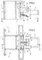
- Fig. 1 shows a shoring device for shoring more than 6 m deep trenches.
- Four supports 1 are shown, each with a length of over 6 m.
- the support feet 2 are chamfered to drive them into the ground.
- the sides of the supports have guide channels 3, in which the edges of shoring plates 4, 5 are guided so as to be vertically displaceable.
- two shoring plates 4 and 5 which are offset to one another by a certain amount are held in the sliding guides 3 of the supports.
- additional pairs of supports and additional shoring panels are added to the shoring unit shown.
- a frame-shaped strut 6 is provided which is guided in a vertically displaceable manner in inner guide channels 7 of two supports 2 located opposite one another.
- the strut 6 consists of a stiffening frame which comprises two horizontal cross struts 8 which can be changed in length by changing the middle parts, and two vertical side struts 9 which connect the ends of the cross struts 8 to one another.
- the stop 10 is arranged on the front left support 1 in the inner sliding guide 7 for the struts 6.
- the weight of the frame-shaped struts 6 blocks the braking device of the stop 10.
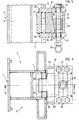
- the stop 10 comprises a T-shaped holding part 13, which consists of a cross plate 14 and a central web 15.
- the free lateral end regions of the cross plate 14 are each provided with a brake lining 16 and each form the first pressure element of a pressure element pair, which clamps in each case a lateral web 17 of the inner guide channel 7 of the support 1.
- the second pressure elements 18 of each pressure element pair are pivotally connected to the central web 15 of the T-shaped holding part 13 via a bearing pin 19.
- the outer contour of the second pressure body 18 is eccentric to the bearing pin 19.
- the pressure body 18 By supporting the vertically downward weight of the struts 6 on the actuating lever 11, the pressure body 18 is pressed in the horizontal direction against the webs 17 of the guide channel 7 and pull the brake pads 16 against the opposite one Contact surface of the webs 17. In this way, the weight of the struts 6 resting on the stop 10 causes the braking device of the stop 10 to be blocked.
- a biasing spring 20 is provided, which is fastened on the one hand to the cross plate 14 of the holding part 13 and on the other hand via a fastening web 21 to the pressure bodies 18.
- the biasing spring 20 pulls the pressure body 18 towards the opposite brake pads 16, and generates a sufficiently high braking force to bear the dead weight of the stop 10.
- the advantage of the separate stop described is that it can be arranged in the guide channel 7 of the support 3 before the spreaders 6 are inserted. This ensures that when the frame-shaped struts 6 are detached the spreader 6 does not slide downward from the excavator shovel during assembly, but is held at a certain height by the stop 10. In this way, the risk of accidents during the installation of the trench shoring device is considerably reduced.
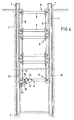
- the braking device forms an integral part of the lowest frame-shaped strut 6.
- a pivot lever 22 is articulated on its lower cross strut 8, at the free end of which a brake shoe 23 is arranged, which forms a pressure body of the braking device .
- the opposite pressure body is formed by a steel rail 24 which is fastened to the left side strut 9 of the lowermost struts 6 and engages behind the lateral webs 17 of the inner guide channel 7 of the support 1.
- a biasing spring 20 pulls the pressure bodies formed by the steel rail 24 and the brake shoe 23 towards one another.
- a locking device which can lock the braking device in the open position.
- the eccentric 25 consists of an eccentric 25 with an actuating lever 26.
- the eccentric 25 is articulated on the cross strut 8 and bears against the pivot lever 22. If the actuating lever 26 is pivoted toward the cross strut 8 until its free end bears against it, the eccentric 25 presses the pivoting lever 22 downward and thus the brake shoe 23 away from the support 1.
- an embodiment of the invention with stop 10 ' is shown, in which the contact pressure, which presses the pressure body 27, 36 of the braking device against one another, is not generated by the weight of the struts but by a manually actuated pressing device.
- the stop 10 ' comprises - similar to the stop 10 shown in FIGS. 2 and 3 - two pressure elements 27, 36 which are movably connected to one another.
- the first pressure element 27 is arranged within the inner guide channel 7 of the support 1, its two lateral areas abutting against the lateral webs 17 of the guide channel 7.
- a cover plate 28 is welded to each of the upper and lower end faces of the first pressure element 27, which protrudes through the mutually opposite webs 17 of the guide channel 7. Outside the guide channel 7 28 side plates 29 are welded to the cover plates, between which the pressing device is arranged.
- the pressing device consists of a threaded element 32 acting as a threaded spindle, which is held in two pairs of holding plates 30, each of which are screwed above and below to the side plates 29 of the stop by means of retaining screws 31.
- the longitudinal direction of the threaded element 32 runs parallel to the longitudinal direction of the inner guide channel 7 or to the longitudinal direction of the support 1.
- an insertion sleeve is welded, into which a lever rod can be inserted in order to exert a large torque on the threaded element 32.
- An adjusting element 34 with an internal thread can be adjusted in the longitudinal direction on the external thread of the threaded element 32.
- the adjusting element 34 has an inclined surface 35 which is inclined to the longitudinal direction of the threaded element 32.
- the second pressure body 36 has an inclined surface 37 that extends complementarily to the inclined surface 35.
- the adjusting element 34 presses the second pressure element 36 onto the first pressure element 27 and thus locks the braking device formed by these two pressure elements 27, 36.
- the stop 10 is closed on the side facing away from the inner guide channel 7 by an end wall 38.
- the braking device according to the invention can be equipped with a large number of different lever linkages in order to convert the weight into a braking force.
Landscapes
- Engineering & Computer Science (AREA)
- Mining & Mineral Resources (AREA)
- Life Sciences & Earth Sciences (AREA)
- General Life Sciences & Earth Sciences (AREA)
- Paleontology (AREA)
- Civil Engineering (AREA)
- General Engineering & Computer Science (AREA)
- Structural Engineering (AREA)
- Braking Arrangements (AREA)
- Closing And Opening Devices For Wings, And Checks For Wings (AREA)
- Supports For Plants (AREA)
- Wing Frames And Configurations (AREA)
Applications Claiming Priority (2)
| Application Number | Priority Date | Filing Date | Title |
|---|---|---|---|
| DE19621826 | 1996-05-31 | ||
| DE1996121826 DE19621826A1 (de) | 1996-05-31 | 1996-05-31 | Anschlag für eine Spreize einer Grabenverbauvorrichtung |
Publications (2)
| Publication Number | Publication Date |
|---|---|
| EP0810328A2 true EP0810328A2 (fr) | 1997-12-03 |
| EP0810328A3 EP0810328A3 (fr) | 1998-08-12 |
Family
ID=7795749
Family Applications (1)
| Application Number | Title | Priority Date | Filing Date |
|---|---|---|---|
| EP97108785A Withdrawn EP0810328A3 (fr) | 1996-05-31 | 1997-06-02 | Butée pour étrésillon utilisé dans le blindage des tranchées |
Country Status (2)
| Country | Link |
|---|---|
| EP (1) | EP0810328A3 (fr) |
| DE (1) | DE19621826A1 (fr) |
Cited By (2)
| Publication number | Priority date | Publication date | Assignee | Title |
|---|---|---|---|---|
| US6821057B1 (en) | 2000-04-05 | 2004-11-23 | Maksim Kadiu | Magnetic shoring device |
| CN114308976A (zh) * | 2021-12-09 | 2022-04-12 | 中建三局集团有限公司 | 一种异形基坑防尘天幕及其安装使用方法 |
Families Citing this family (1)
| Publication number | Priority date | Publication date | Assignee | Title |
|---|---|---|---|---|
| US7056067B2 (en) | 2003-10-03 | 2006-06-06 | Max Kadiu | Trench shoring device |
Family Cites Families (5)
| Publication number | Priority date | Publication date | Assignee | Title |
|---|---|---|---|---|
| DE2560498C2 (de) * | 1975-12-18 | 1985-06-27 | Ischebeck, Döpp & Co, 5828 Ennepetal | Verbaueinheit zum Aussteifen der Wände von Baugräben, Rohrgräben oder dergleichen |
| JPS56156323A (en) * | 1980-05-07 | 1981-12-03 | Hiroshi Ito | Simple soil sheathing work |
| DE3219636A1 (de) * | 1982-05-25 | 1983-12-01 | Josef Ing.(grad.) 5142 Hückelhoven Emunds | Spannrahmen fuer verbauplatten |
| DE4028832A1 (de) * | 1990-09-11 | 1992-03-12 | Wilhelm Hess | Verfahren und vorrichtung zum verbau tiefer graeben |
| US5513555A (en) * | 1994-01-21 | 1996-05-07 | Michael J. Plank | Quick-release cam lock with locking pin |
-
1996
- 1996-05-31 DE DE1996121826 patent/DE19621826A1/de not_active Withdrawn
-
1997
- 1997-06-02 EP EP97108785A patent/EP0810328A3/fr not_active Withdrawn
Cited By (2)
| Publication number | Priority date | Publication date | Assignee | Title |
|---|---|---|---|---|
| US6821057B1 (en) | 2000-04-05 | 2004-11-23 | Maksim Kadiu | Magnetic shoring device |
| CN114308976A (zh) * | 2021-12-09 | 2022-04-12 | 中建三局集团有限公司 | 一种异形基坑防尘天幕及其安装使用方法 |
Also Published As
| Publication number | Publication date |
|---|---|
| EP0810328A3 (fr) | 1998-08-12 |
| DE19621826A1 (de) | 1997-12-04 |
Similar Documents
| Publication | Publication Date | Title |
|---|---|---|
| EP1679462B1 (fr) | Appareil pour pose de tuyau | |
| DE2040328B2 (de) | Fahrbare Rauminnenschalung für Beton und Stahlbetonbauten | |
| EP4682327A2 (fr) | Procédé de connexion sécurisée auto-activable d'une console d'escalade avec un dispositif d'ancrage et console d'escalade | |
| EP3789550A1 (fr) | Dispositif d'encliquetage | |
| EP1355009A2 (fr) | Dispositif de recouvrement pour joints | |
| EP2288770A2 (fr) | Dispositif pour démolir des constructions | |
| EP4279659B1 (fr) | Appareil d'excavation de tranchées pour parois moulées et procédé d'excavation d'une paroi moulée dans le sol | |
| DE19511206C2 (de) | Hochbauentwässerungsrinne | |
| EP0687784A1 (fr) | Rigole de drainage pour bâtiments | |
| DE3005135A1 (de) | Vorrichtung zum zusammenziehen von rohren | |
| EP0166794A1 (fr) | Dispositif pour la connexion des barres profilées d'une étagère | |
| EP0810328A2 (fr) | Butée pour étrésillon utilisé dans le blindage des tranchées | |
| DE9412270U1 (de) | Verlegbare Brücke | |
| EP4112816B1 (fr) | Appareil d'excavation de tranchées pour parois moulées et procédé d'excavation d'une paroi moulée dans le sol | |
| EP0167991A2 (fr) | Dispositif de tête à pivot pour l'assemblage articulé et en tout temps démontable d'un étrésillon de tranchée à une paroi de blindage | |
| EP0393448A1 (fr) | Equipement d'étançonnage pour l'étrésillonnement de tranchées | |
| EP2698474A1 (fr) | Dispositif de pose de pavés avec un dispositif de support de mâchoires de préhension | |
| DE29704533U1 (de) | Zwischenlage zur Höhenmäßigen Distanzierung und Abstützung von Langschienen | |
| DE102006043547B4 (de) | Formsteinverlegevorrichtung mit an unebene Formsteinlagen anpassbarer Greifeinrichtung | |
| EP3848532A1 (fr) | Agencement de support de plaque d'ombrage et procédé de positionnement d'un support de plaque d'ombrage sur une console | |
| DE3822289C2 (fr) | ||
| DE102022125081B3 (de) | Bodenstütze eines Kabeltragsystems | |
| DE19604933B4 (de) | Haltepratze | |
| DE9414199U1 (de) | Vorrichtung zur Schnellabsenkung einer Baustütze | |
| DE102020100753A1 (de) | Höhenverstellbares Schachtringelement |
Legal Events
| Date | Code | Title | Description |
|---|---|---|---|
| PUAI | Public reference made under article 153(3) epc to a published international application that has entered the european phase |
Free format text: ORIGINAL CODE: 0009012 |
|
| AK | Designated contracting states |
Kind code of ref document: A2 Designated state(s): AT DE ES FR GB |
|
| PUAL | Search report despatched |
Free format text: ORIGINAL CODE: 0009013 |
|
| AK | Designated contracting states |
Kind code of ref document: A3 Designated state(s): AT DE ES FR GB IT |
|
| 17P | Request for examination filed |
Effective date: 19990205 |
|
| AKX | Designation fees paid |
Free format text: AT DE ES FR GB |
|
| RBV | Designated contracting states (corrected) |
Designated state(s): AT DE ES FR GB |
|
| GRAG | Despatch of communication of intention to grant |
Free format text: ORIGINAL CODE: EPIDOS AGRA |
|
| GRAG | Despatch of communication of intention to grant |
Free format text: ORIGINAL CODE: EPIDOS AGRA |
|
| GRAH | Despatch of communication of intention to grant a patent |
Free format text: ORIGINAL CODE: EPIDOS IGRA |
|
| 17Q | First examination report despatched |
Effective date: 20010503 |
|
| RIN1 | Information on inventor provided before grant (corrected) |
Inventor name: TRITSCHLER, KARL-HEINZ |
|
| STAA | Information on the status of an ep patent application or granted ep patent |
Free format text: STATUS: THE APPLICATION IS DEEMED TO BE WITHDRAWN |
|
| 18D | Application deemed to be withdrawn |
Effective date: 20011002 |