EP4279659B1 - Appareil d'excavation de tranchées pour parois moulées et procédé d'excavation d'une paroi moulée dans le sol - Google Patents
Appareil d'excavation de tranchées pour parois moulées et procédé d'excavation d'une paroi moulée dans le sol Download PDFInfo
- Publication number
- EP4279659B1 EP4279659B1 EP22174149.9A EP22174149A EP4279659B1 EP 4279659 B1 EP4279659 B1 EP 4279659B1 EP 22174149 A EP22174149 A EP 22174149A EP 4279659 B1 EP4279659 B1 EP 4279659B1
- Authority
- EP
- European Patent Office
- Prior art keywords
- diaphragm wall
- base frame
- bracing
- intermediate frame
- frame
- Prior art date
- Legal status (The legal status is an assumption and is not a legal conclusion. Google has not performed a legal analysis and makes no representation as to the accuracy of the status listed.)
- Active
Links
Images



Classifications
-
- E—FIXED CONSTRUCTIONS
- E02—HYDRAULIC ENGINEERING; FOUNDATIONS; SOIL SHIFTING
- E02F—DREDGING; SOIL-SHIFTING
- E02F3/00—Dredgers; Soil-shifting machines
- E02F3/04—Dredgers; Soil-shifting machines mechanically-driven
- E02F3/18—Dredgers; Soil-shifting machines mechanically-driven with digging wheels turning round an axis, e.g. bucket-type wheels
- E02F3/20—Dredgers; Soil-shifting machines mechanically-driven with digging wheels turning round an axis, e.g. bucket-type wheels with tools that only loosen the material, i.e. mill-type wheels
- E02F3/205—Dredgers; Soil-shifting machines mechanically-driven with digging wheels turning round an axis, e.g. bucket-type wheels with tools that only loosen the material, i.e. mill-type wheels with a pair of digging wheels, e.g. slotting machines
-
- E—FIXED CONSTRUCTIONS
- E02—HYDRAULIC ENGINEERING; FOUNDATIONS; SOIL SHIFTING
- E02D—FOUNDATIONS; EXCAVATIONS; EMBANKMENTS; UNDERGROUND OR UNDERWATER STRUCTURES
- E02D17/00—Excavations; Bordering of excavations; Making embankments
- E02D17/13—Foundation slots or slits; Implements for making these slots or slits
-
- E—FIXED CONSTRUCTIONS
- E02—HYDRAULIC ENGINEERING; FOUNDATIONS; SOIL SHIFTING
- E02F—DREDGING; SOIL-SHIFTING
- E02F3/00—Dredgers; Soil-shifting machines
- E02F3/04—Dredgers; Soil-shifting machines mechanically-driven
- E02F3/46—Dredgers; Soil-shifting machines mechanically-driven with reciprocating digging or scraping elements moved by cables or hoisting ropes ; Drives or control devices therefor
- E02F3/47—Dredgers; Soil-shifting machines mechanically-driven with reciprocating digging or scraping elements moved by cables or hoisting ropes ; Drives or control devices therefor with grab buckets
- E02F3/475—Dredgers; Soil-shifting machines mechanically-driven with reciprocating digging or scraping elements moved by cables or hoisting ropes ; Drives or control devices therefor with grab buckets for making foundation slots
-
- E—FIXED CONSTRUCTIONS
- E02—HYDRAULIC ENGINEERING; FOUNDATIONS; SOIL SHIFTING
- E02F—DREDGING; SOIL-SHIFTING
- E02F3/00—Dredgers; Soil-shifting machines
- E02F3/04—Dredgers; Soil-shifting machines mechanically-driven
- E02F3/46—Dredgers; Soil-shifting machines mechanically-driven with reciprocating digging or scraping elements moved by cables or hoisting ropes ; Drives or control devices therefor
- E02F3/58—Component parts
Definitions
- the invention relates to a diaphragm wall device for creating a slit in the ground, with a base frame which extends in a longitudinal direction, at least one soil removal device which is arranged at a lower end region of the base frame, a holding device at an upper end region of the diaphragm wall device, a bracing device with at least two opposing clamping elements which can be moved laterally, transversely to the longitudinal direction, and at least one adjusting element by means of which the clamping elements can be extended laterally in order to brace at least part of the diaphragm wall device in the slit, an intermediate frame which is slidably mounted along the base frame in a lower region of the base frame and on which the bracing device with the at least two clamping elements and the at least one adjusting element is arranged, and a pressure device by means of which a pressure force can be applied to the at least one soil removal device, wherein the pressure device is arranged between the intermediate frame and the base frame, according to the preamble of claim 1.
- the invention further relates to a method for creating a slit in the ground with such a slit wall device according to the preamble of claim 13.
- Such diaphragm wall machines are known in particular as so-called diaphragm wall cutters with cutting wheels as soil removal devices. These are usually suspended from a carrier device via a support cable. At the upper end of the base frame is A holding device for a support cable, a support rod or similar is arranged. This means that the maximum pressure force on the ground is limited by the weight of the diaphragm wall device.
- a trench wall cutter is known in which longitudinally and transversely movable clamping plates are provided on a cutter frame, which together with transversely directed clamping cylinders form a unit.
- the clamping cylinders are each supported on the opposite clamping plates.
- the unit formed from clamping plates and clamping cylinders is mounted so that it can move in the transverse direction relative to a base frame of the cutter, so that the unit is overall floatingly mounted.
- this floating mounting prevents the position of the base frame suspended from a support cable from shifting.
- an arrangement of vertically directed pressure cylinders is provided below the unit with the clamping plates.
- the EP 0 593 355 A1 teaches a similar floating support of clamping plates in a transverse direction.
- the clamping plates are arranged on a common piston and can therefore be moved together in the transverse direction.
- a trench cutter with a base frame and a lower vertically movable tool carrier part with the cutting wheels is from the EP 0 811 724 B1
- the base frame which is held by a support cable, can be clamped in the milling slot using transverse clamping elements, while the milling wheels can be moved downwards.
- a trench wall cutter is known in which transversely directed adjusting elements are also supported on the one hand on a first clamping plate and on the other hand on a second opposite clamping plate.
- additional clamping cylinders are provided which are directed diagonally downwards and can be used to additionally clamp the individual clamping plates against an intermediate frame.
- the intermediate frame is guided on a base frame of the cutter so that it can be moved in the direction of advance.
- a tensile force can be applied to the cutter wheels via upper diagonally directed pressure cylinders to apply an additional propulsive force.
- a holding device for a support cable is attached to the base frame.
- the DE 38 05 868 shows a diaphragm wall device according to the preamble of claim 1.
- This diaphragm wall device has a relatively large and massive "intermediate frame” at the upper end of a "base frame”.
- This "intermediate frame” with its large mass cannot contribute any (weight) force in the direction of advance when it is braced. This mass is therefore ineffective and inefficient when it is braced.
- the invention is based on the object of specifying a diaphragm wall device and a method with which a slit in the ground can be efficiently created with a compact design of the diaphragm wall device.
- the diaphragm wall device according to the invention is characterized in that the intermediate frame is mounted so as to be displaceable along the base frame in a lower area of the base frame and that the holding device is firmly connected to the intermediate frame via one or more longitudinal beams which extend along the base frame.
- a first aspect of the invention consists in attaching the holding device for holding the diaphragm wall device not directly to the base frame with the soil removal device, but to the intermediate frame with the bracing device.
- the base frame with the soil removal device is thus displaceable in the advance direction not only relative to the intermediate frame with the bracing device, but also relative to the holding device. This allows the advance of the Soil removal equipment, in particular milling wheels, can be moved on the base frame without the holding device having to be adjusted.
- the holding device is intended to be connected in particular to a support cable or a support rod on a carrier device.
- the soil removal device can thus be moved without a support cable or the support rod having to be adjusted on the carrier device. This simplifies the control of the feed movement and a desired pressure force. This can now be done in particular by controlling the pressure device alone.
- the intermediate frame with the bracing device is arranged in a lower area of the diaphragm wall device.
- the diaphragm wall device can be braced to the walls of a previously formed guide slot.
- the base frame is guided on the intermediate frame in a substantially vertical direction and a desired pressure force can be applied to the soil removal device at an early stage.
- the holding device is firmly connected to the intermediate frame via one or more longitudinal beams which extend along the base frame.
- a single longitudinal beam can be sufficient, via which the intermediate frame arranged in a lower area is firmly connected to the holding device in the upper area of the diaphragm wall device.
- two or more, in particular four, longitudinal beams are preferably arranged, preferably along the outer sides of the base frame.
- the longitudinal beams can each be designed in particular as double-T beams.
- corresponding channel-shaped recesses are provided along the base frame for the longitudinal beams, so that they do not protrude beyond the outer dimensions of the base frame.
- a particularly robust design of the diaphragm wall device is achieved by attaching the holding device to a cross member which is arranged in an upper area of the base frame.
- the holding device which can be a connecting element or a coupling element for attaching a support cable or support rod, can be arranged centrally and/or along a longitudinal axis of the Diaphragm wall device. With this central arrangement, a good connection to the external longitudinal beams can be made via at least one cross beam.
- a further preferred embodiment of the invention consists in that the tensioning device has at least two adjusting elements arranged perpendicular to the longitudinal direction, wherein at least one first adjusting element is mounted on the one hand on the intermediate frame and on the other hand on a first clamping element and at least one second adjusting element is mounted on the one hand on the intermediate frame and on the other hand on a second clamping element which is arranged opposite the first clamping element and that the first adjusting elements and the second adjusting elements can be extended perpendicular to the longitudinal direction.
- Each plate-shaped tensioning element can be assigned at least one individual adjusting element, in particular a tensioning cylinder, which is supported on the one hand on the respective tensioning element and on the other hand on the intermediate frame.
- the adjusting elements are directed transversely to the longitudinal or advance direction of the diaphragm wall device. This allows the individual tensioning elements to be adjusted individually in relation to the intermediate frame. In addition, a clear separation is achieved between the transverse forces and the longitudinal forces for pressing the diaphragm wall device, which overall contributes to a compact structure and efficient operation.
- opposing tensioning elements can also be attached to a common holder or adjusting device, with the holder being mounted on the base frame in a floating manner so that it can be moved in a transverse and/or longitudinal direction.
- a compact structure is further promoted according to a further development of the invention in that the intermediate frame is slidably mounted on the base frame on a bearing section which has a reduced cross-section compared to the base frame, forming at least one free space, and in that at least one receptacle for receiving at least part of the actuating element is formed on the slidable intermediate frame, the receptacle being arranged in the free space formed.
- actuating elements which are actuators or linear drives, in particular clamping cylinders, preferably hydraulic cylinders.
- two lateral free spaces are formed on the bearing section and that two receptacles for adjusting elements are formed on the intermediate frame.
- the adjusting elements for the opposite clamping elements can thus be arranged in the two lateral receptacles. At least one first adjusting element and at least one second adjusting element for the opposite clamping elements are provided in each lateral receptacle.
- the holder can be open and designed with only one base plate to which the respective adjusting element is attached and supported. Opposite adjusting elements can support each other on the same base plate, whereby the transverse forces on the base plate largely compensate for each other.
- the at least one holder on the intermediate frame is designed in a box-like manner and has at least one first adjusting element and at least one second adjusting element.
- the box-like holder has side walls which face the respective plate-shaped clamping elements, whereby the side walls each have at least one passage for at least one of the adjusting elements and at least one support area for attaching the adjusting element facing the opposite clamping element.
- first adjusting elements and several second adjusting elements are arranged in a receptacle of the intermediate frame.
- two first adjusting elements and two second adjusting elements are arranged in each receptacle, which are each directed in opposite directions transverse to the longitudinal direction.
- a control is provided by which the first actuating elements and the second actuating elements can be extended in a defined manner.
- the actuating elements can be extended evenly so that the individual clamping elements come to rest on the surrounding walls of the slot as simultaneously as possible, so that no change in the position of the base frame of the slot wall device is caused in the slot.
- control is designed to initially extend the at least one first actuating element and the at least one second actuating element with a first low pressure force until the clamping elements rest against the surrounding floor, and then to apply a high pressure force for clamping.
- the high clamping force required for clamping is only initiated by the control device in particular when no further extension movement is detected on the actuating elements when the first adjustment force is applied. This can be interpreted as an indication that the respective clamping elements have come into a clamping position to rest against the respective adjacent wall when they are extended.
- control device is connected to sensors by which a pressing force and/or an extended position of the actuating elements can be detected.
- the pressing force can be detected at the individual actuating elements or centrally for groups of actuating elements or for all actuating elements as a whole.
- a further preferred embodiment of the invention is that the pressure device is arranged above the bracing device and has at least one, preferably several pressure cylinders.
- the bracing device can be arranged very close to the soil removal device. This allows the diaphragm wall device to be braced very early in the slot formed, so that additional pressure forces can be applied to the soil removal device at an early stage of a foundation process.
- the pressure cylinder(s) are designed in such a way that they exert a tensile force on the base frame in order to apply the pressure force. By contracting the at least one pressure cylinder, the base frame and thus the soil removal device can be pulled downwards with a desired force.
- each pressure cylinder is attached to the base frame on the one hand and to the intermediate frame or a clamping element on the other. This allows a direct flow of force when pressing between the longitudinal movable base frame and the fixed intermediate frame or the respective clamping element.
- the at least one pressure cylinder can be arranged parallel to the longitudinal direction of the diaphragm wall device.
- a particularly compact arrangement is obtained according to an embodiment of the invention in that the pressure cylinders are arranged inclined to the vertical, whereby the base frame with the soil removal device can be pressed downwards relative to the braced intermediate frame by actuating the pressure cylinders.
- the diaphragm wall device is designed as a diaphragm wall cutter, wherein the soil removal device has at least one cutting wheel.
- the soil removal device has at least one cutting wheel.
- two pairs of driven cutting wheels with mutually parallel cutting wheel axes are arranged at the lower end of the base frame as a soil removal device.
- An alternative embodiment of the invention is a diaphragm wall device which is designed as a diaphragm wall grab, wherein the soil removal device has grab blades.
- a particularly high removal rate can be achieved by the bracing device designed according to the invention, particularly when inserting and closing the grab blades in the soil.
- the invention further comprises a method for creating a slot in the ground using the previously described diaphragm wall device according to the invention, the method being characterized in that the diaphragm wall device is held at an upper end region by means of a holding device, that soil is removed by means of at least one soil removal device, which is arranged at a lower end region of the base frame, to form the slot, that at least two opposing clamping elements are extended laterally by means of a bracing device by at least two adjusting elements directed perpendicular to the longitudinal direction, wherein at least a part of the diaphragm wall device is braced in the slot, that a pressing force is applied to the at least one soil removal device by means of a pressing device, that the clamping device with the at least two clamping elements and the adjusting elements is arranged on an intermediate frame to which the holding device is attached and the The base frame is mounted so as to be displaceable relative to the intermediate frame and the holding device, the intermediate frame is braced and fixed relative to the ground by the brac
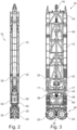
- a diaphragm wall device 10 according to the invention with an elongated base frame 12 is shown in Fig. 1 to 3
- the base frame 12 which is preferably scaffold-like and rectangular in cross section, can have a tapered Bearing section 16, which is also designed with a basically rectangular cross-section.
- the soil removal device 20 for removing soil material can be arranged on an underside of the bearing section 16.
- the soil removal device 20 is formed by four milling wheels 22, two of which form a milling wheel pair with a common milling wheel axis.
- the milling wheels 22 of a milling wheel pair are each rotatably mounted and driven on a central bearing plate in a manner known in principle.
- a suction box 18 can be arranged between the two pairs of milling wheels 22 in a manner also known in principle, which serves to suck up milled soil material.
- the central suction line along the base frame 12 is not shown in detail for reasons of clarity.
- An intermediate frame 60 with a bracing device 50 is mounted so that it can be moved longitudinally on the bearing section 16 of the base frame 12.
- the intermediate frame 60 can have two front plates 62, which can be connected to one another via two outer side plates 64 and two inner side plates 66, so that the box-like intermediate frame 60 encloses the rectangular bearing section 16 in a ring-like manner and is mounted so that it can be moved longitudinally thereon.
- An outer side plate 64 and an inner side plate can be arranged at a distance from each other on two short sides of the intermediate frame 60, wherein a box-like receptacle 70 can be formed between them.
- the two lateral receptacles 70 are located in the two free spaces 17, which are formed by the tapering of the bearing section 16 relative to the base frame 12.
- two first adjusting elements pointing forwards and two second adjusting elements pointing backwards can be arranged in the receptacles 70, which are designed in particular as hydraulic cylinders.
- Side plate-shaped clamping elements 52 can be extended and retracted laterally via the adjusting elements in order to clamp the diaphragm wall device 10 in the milling slot.
- pressure cylinders 32 are provided to form a pressure device 30.
- Two pressure cylinders 32 are arranged on a front side and two pressure cylinders 32 on a back side of the base frame 12.
- Each pressure cylinder 32 is hinged with its cylinder housing to a bearing block 36 which is fastened to the base frame 12.
- the piston rod of each pressure cylinder 32 is connected to the associated plate-shaped clamping element 52 via a pivot pin connection 38.
- the pressure cylinders 32 can be used to move the base frame 12 relative to the intermediate frame 60.
- the cutting wheels 22 can be moved from an upwardly retracted position, which is in the Figures 1 to 3 shown, in a lower position according to Fig.4 in which the cutting wheels 22 protrude downwards relative to the intermediate frame 60 with the clamping device 50.
- the pressure cylinders 32 can be retracted, as for example from Fig.4 emerges.
- a holding device 14 is arranged in an upper area, with which the diaphragm wall device 10 can be attached to a support cable or a support rod.
- the holding device 14, which is in Fig.5 shown in more detail, can have a shaft 15 and is mounted on the base frame 12 so as to be displaceable in the longitudinal direction via a sleeve-shaped linear guide 13 and is fastened to a cross member 42.
- the cross member 42 is firmly connected to the intermediate frame 60 with the bracing device 50 via one or more longitudinal members 40.
- the diaphragm wall device 10 is held via the holding device 14 and the intermediate frame 60, wherein the base frame 12 is freely displaceable in the longitudinal direction relative to the holding device 14 with the pressure cylinders 32.
- Guide plates 11 can be attached to the outside of the base frame 12 for guidance within the milled slot. The guide plates 11 can be controlled and displaceable in order to align the diaphragm wall cutter 10 in the milled slot.
- a lower portion of the diaphragm wall device 10 according to the invention is in a state corresponding to the Figures 1 to 3 shown, in which the plate-shaped clamping elements 52 of the clamping device 50 can be retracted so that the diaphragm wall device 10 can be moved freely in a slot in the ground.
- the pressure cylinders 32 of the pressure device 30 are extended, with the intermediate frame 60 being moved to a lower end of the bearing section 16.
- the bracing device 50 is activated.
- the adjusting elements which cannot be seen and are arranged in the receptacles 70, preferably transversely directed hydraulic cylinders, are extended, whereby the plate-shaped clamping elements 52 are pressed against the surrounding ground walls.
- the pressure device 30 can be activated, as shown in Fig.7 is shown.
- the pressure cylinders 32 are retracted, and due to the fixing of the intermediate frame 60 by the extended clamping elements 52, the base frame 12 together with the bearing section 16 and the soil removal device 20 are pressed downwards by the pulling movement generated by the pressure cylinders 32.
- an additional downward force can be applied to the soil removal device 20 by the pressure cylinders 32. This can be advantageous when milling hard soil, particularly rock material.
- the weight of the diaphragm wall device 10 can be absorbed in whole or in part by the bracing device 50 and diverted into the surrounding soil. This can be advantageous in soft soils, for example if too great a downward force causes the soil to be compacted too much, which can make removal more difficult.
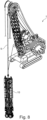
- the intermediate frame 60 with the bracing device 50 can be held on a support cable 5 of a support unit 1 via the longitudinal beams 40 and the holding device 14, as shown in Fig.8
- the carrier unit 1 can be a mobile crane with a boom arm. The carrier unit 1 can be used to supply the necessary fluids are supplied and removed and energy is supplied.
Landscapes
- Engineering & Computer Science (AREA)
- Mining & Mineral Resources (AREA)
- Civil Engineering (AREA)
- General Engineering & Computer Science (AREA)
- Structural Engineering (AREA)
- Mechanical Engineering (AREA)
- Life Sciences & Earth Sciences (AREA)
- General Life Sciences & Earth Sciences (AREA)
- Paleontology (AREA)
- Pit Excavations, Shoring, Fill Or Stabilisation Of Slopes (AREA)
- Bulkheads Adapted To Foundation Construction (AREA)
- Conveying And Assembling Of Building Elements In Situ (AREA)
Claims (13)
- Engin pour parois moulées pour réaliser une fente dans le sol, avec- un cadre de base (12) s'étendant dans une direction longitudinale,- au moins un dispositif d'enlèvement de sol (20), qui est disposé sur une zone d'extrémité inférieure du cadre de base (12),- un dispositif de maintien (14) pour maintenir l'engin pour parois moulées (10) au niveau de sa partie supérieure,- un dispositif de calage (50) avec au moins deux éléments de calage (52) opposés et déplaçables latéralement, transversalement à la direction longitudinale, ainsi qu'au moins un élément d'ajustement par lequel les éléments de calage (52) peuvent être sortis latéralement pour caler au moins une partie de l'engin pour parois moulées (10) dans la fente,- un cadre intermédiaire (60), sur lequel est disposé le dispositif de calage (50) avec les au moins deux éléments de calage (52) et le au moins un élément d'ajustement, et- un dispositif de poussée (30), par lequel une force de poussée peut être appliquée sur le au moins un dispositif d'enlèvement de sol (20),- le dispositif de poussée (30) étant disposé entre le cadre intermédiaire (60) et le cadre de base (12), de sorte qu'au moyen du dispositif de poussée (30), le cadre de base (12) peut être déplacé par rapport au cadre intermédiaire (60),- le dispositif de maintien (14) étant relié de manière fixe au cadre intermédiaire (60) et- le cadre de base (12) avec le dispositif d'enlèvement de sol (20) pouvant être déplacé par rapport au dispositif de maintien (14),caractérisé- en ce que le cadre intermédiaire (60) est logé de manière déplaçable le long du cadre de base (12) dans une zone inférieure du cadre de base (12) et- en ce que le dispositif de maintien (14) est relié de manière fixe au cadre intermédiaire (60) par un ou plusieurs longerons (40) qui s'étendent le long du cadre de base (12).
- Engin pour parois moulées selon la revendication 1,
caractérisé- en ce que le dispositif de maintien (14) est monté sur une traverse (42) qui est disposée dans une zone supérieure du cadre de base (12), et- en ce qu'un guidage linéaire (13) est disposé dans la zone de la traverse (42), avec lequel le cadre de base (12) est guidé en coulissement par rapport au dispositif de maintien (14). - Engin pour parois moulées selon l'une des revendications 1 à 2,
caractérisé- en ce que le dispositif de calage (50) présente au moins deux éléments d'ajustement disposés perpendiculairement à la direction longitudinale, au moins un premier élément d'ajustement étant monté d'une part sur le cadre intermédiaire (60) et d'autre part sur un premier élément de calage (52), et au moins un deuxième élément d'ajustement étant monté d'une part sur le cadre intermédiaire (60) et d'autre part sur un deuxième élément de calage (52) qui est disposé en face du premier élément de calage (52), et- en ce que le premier élément d'ajustement et le deuxième élément d'ajustement peuvent être sortis perpendiculairement à la direction longitudinale. - Engin pour parois moulées selon l'une des revendications 1 à 3,
caractérisé
en ce que le cadre intermédiaire (60) est monté de manière à pouvoir coulisser sur le cadre de base (12) dans une zone inférieure sur une section de palier (16) laquelle présente une coupe transversale réduite par rapport au cadre de base (12) en formant au moins un espace libre (17). - Engin pour parois moulées selon la revendication 4,
caractérisé
en ce que deux espaces libres latéraux (17) sont formés sur la section de palier (16) et en ce que deux logements (70) pour des éléments d'ajustement sont formés en conséquence sur le cadre intermédiaire (60). - Engin pour parois moulées selon la revendication 5,
caractérisé
en ce que l'au moins un logement (70) est réalisé en forme de caisson sur le cadre intermédiaire (60) et présente au moins un premier élément d'ajustement et au moins un deuxième élément d'ajustement. - Engin pour parois moulées selon l'une des revendications 1 à 6,
caractérisé
en ce qu'il est prévu une commande par laquelle les premiers éléments d'ajustement et les deuxièmes éléments d'ajustement peuvent être sortis de manière définie. - Engin pour parois moulées selon l'une des revendications 1 à 5,
caractérisé
en ce que le dispositif de poussée (30) est disposé au-dessus du dispositif de calage (50) et présente au moins un, de préférence plusieurs cylindres de pression (32). - Engin pour parois moulées selon la revendication 8,
caractérisé
en ce que chaque cylindre de pression (32) est monté d'une part sur le cadre de base (12) et d'autre part sur le cadre intermédiaire (60) ou sur un élément de calage (52). - Engin pour parois moulées selon la revendication 8 ou 9,
caractérisé
en ce que les cylindres de pression (32) sont disposés de manière inclinée par rapport à la verticale, l'actionnement des cylindres de pression (32) permettant de pousser le cadre de base (12) avec le dispositif d'enlèvement de sol (20) vers le bas par rapport au cadre intermédiaire (60) calé. - Engin pour parois moulées selon l'une des revendications 1 à 10,
caractérisé
en ce que celui-ci est réalisé sous la forme d'une fraiseuse à parois moulées, le dispositif d'enlèvement de sol (20) présentant au moins une roue de fraisage (22). - Engin pour parois moulées selon l'une des revendications 1 à 10,
caractérisé
en ce que celui-ci est réalisé sous la forme d'un grappin à parois moulées, le dispositif d'enlèvement de sol (20) présentant des pelles de grappin. - Procédé pour réaliser une fente dans le sol avec un engin pour parois moulées (10) selon l'une des revendications 1 à 12,
caractérisé- en ce qu'au moyen d'un dispositif de maintien (14), l'engin pour parois moulées (10) est maintenu sur une zone d'extrémité supérieure,- en ce qu'au moyen d'au moins un dispositif d'enlèvement de sol (20), qui est disposé sur une zone d'extrémité inférieure du cadre de base (12), du sol est enlevé pour former la fente,- en ce qu'au moyen d'un dispositif de calage (50), au moins deux éléments de calage (52) opposés sont sortis latéralement par au moins deux éléments d'ajustement orientés perpendiculairement à la direction longitudinale, au moins une partie de l'engin pour parois moulées (10) étant calé dans la fente,- en ce qu'une force de poussée est appliquée au moyen d'un dispositif de poussée (30) sur le au moins un dispositif d'enlèvement de sol (20),- en ce que le dispositif de calage (50) est disposé avec les au moins deux éléments de calage (52) et les éléments d'ajustement sur un cadre intermédiaire (60) sur lequel est monté le dispositif de maintien (14) et le cadre de base (12) est logé de manière coulissante par rapport au cadre intermédiaire (60) et au dispositif de maintien (14),- en ce que le cadre intermédiaire (60) est calé par le dispositif de calage (50) et fixé par rapport au sol, et- en ce qu'au moyen du dispositif de poussée (30), le cadre de base (12) avec le dispositif d'enlèvement de sol (20) est poussé vers le bas et déplacé par rapport au cadre intermédiaire (60) et au dispositif de retenue (14).
Priority Applications (6)
| Application Number | Priority Date | Filing Date | Title |
|---|---|---|---|
| EP22174149.9A EP4279659B1 (fr) | 2022-05-18 | 2022-05-18 | Appareil d'excavation de tranchées pour parois moulées et procédé d'excavation d'une paroi moulée dans le sol |
| PCT/EP2023/061267 WO2023222363A1 (fr) | 2022-05-18 | 2023-04-28 | Dispositif de coupe de tranchée et procédé de réalisation d'une tranchée dans le sol |
| CN202380037208.8A CN119110864A (zh) | 2022-05-18 | 2023-04-28 | 用于在土地中构建槽的墙开槽设备和方法 |
| CA3259704A CA3259704A1 (fr) | 2022-05-18 | 2023-04-28 | Dispositif de paroi de tranchée et procédé de création d’une tranchée dans le sol |
| KR1020247036879A KR20240168455A (ko) | 2022-05-18 | 2023-04-28 | 그라운드에 트렌치를 생성하기 위한 트렌치 벽 장치 및 방법 |
| US18/862,108 US20250283293A1 (en) | 2022-05-18 | 2023-04-28 | Trench wall device and method for creating a trench in the ground |
Applications Claiming Priority (1)
| Application Number | Priority Date | Filing Date | Title |
|---|---|---|---|
| EP22174149.9A EP4279659B1 (fr) | 2022-05-18 | 2022-05-18 | Appareil d'excavation de tranchées pour parois moulées et procédé d'excavation d'une paroi moulée dans le sol |
Publications (3)
| Publication Number | Publication Date |
|---|---|
| EP4279659A1 EP4279659A1 (fr) | 2023-11-22 |
| EP4279659B1 true EP4279659B1 (fr) | 2024-07-24 |
| EP4279659C0 EP4279659C0 (fr) | 2024-07-24 |
Family
ID=82058479
Family Applications (1)
| Application Number | Title | Priority Date | Filing Date |
|---|---|---|---|
| EP22174149.9A Active EP4279659B1 (fr) | 2022-05-18 | 2022-05-18 | Appareil d'excavation de tranchées pour parois moulées et procédé d'excavation d'une paroi moulée dans le sol |
Country Status (6)
| Country | Link |
|---|---|
| US (1) | US20250283293A1 (fr) |
| EP (1) | EP4279659B1 (fr) |
| KR (1) | KR20240168455A (fr) |
| CN (1) | CN119110864A (fr) |
| CA (1) | CA3259704A1 (fr) |
| WO (1) | WO2023222363A1 (fr) |
Families Citing this family (2)
| Publication number | Priority date | Publication date | Assignee | Title |
|---|---|---|---|---|
| EP4063568B1 (fr) * | 2021-03-23 | 2023-10-04 | BAUER Maschinen GmbH | Dispositif de mesure et dispositif d'enlèvement doté d'un dispositif de mesure |
| DE102024107099A1 (de) * | 2024-03-13 | 2025-09-18 | Liebherr-Werk Nenzing Gmbh | Bodenbearbeitungsgerät, insbesondere Schlitzwandfräse |
Family Cites Families (7)
| Publication number | Priority date | Publication date | Assignee | Title |
|---|---|---|---|---|
| DE3805868A1 (de) * | 1988-02-25 | 1989-09-07 | Hochtief Ag Hoch Tiefbauten | Seilgefuehrter schlitzwandgreifer |
| FR2696769B1 (fr) | 1992-10-12 | 1994-12-09 | Sol Cie | Appareil pour creuser dans le sol des tranchées de grande profondeur à l'aide de tambours de fraisage. |
| FR2749333B1 (fr) | 1996-06-04 | 1998-08-28 | Sol Comp Du | Appareil a chassis telescopique pour creuser des tranchees dans le sol |
| EP2378002B1 (fr) * | 2010-04-16 | 2013-07-17 | BAUER Maschinen GmbH | Dispositif de pelousage pour établir une fente s'étendant verticalement dans le sol |
| FR3041024B1 (fr) | 2015-09-10 | 2017-09-29 | Soletanche Freyssinet | Machine de forage munie d'un dispositif d'ancrage permettant un deplacement horizontal du module de forage en position ancree |
| FR3041025B1 (fr) * | 2015-09-10 | 2017-09-29 | Soletanche Freyssinet | Machine de forage suspendue a un cable de sustentation fixe au module de forage |
| EP3401444B1 (fr) | 2017-05-11 | 2019-11-27 | BAUER Maschinen GmbH | Dispositif d'excavation de tranchée et procédé de fabrication de tranchées dans le sol |
-
2022
- 2022-05-18 EP EP22174149.9A patent/EP4279659B1/fr active Active
-
2023
- 2023-04-28 CA CA3259704A patent/CA3259704A1/fr active Pending
- 2023-04-28 CN CN202380037208.8A patent/CN119110864A/zh active Pending
- 2023-04-28 KR KR1020247036879A patent/KR20240168455A/ko active Pending
- 2023-04-28 US US18/862,108 patent/US20250283293A1/en active Pending
- 2023-04-28 WO PCT/EP2023/061267 patent/WO2023222363A1/fr not_active Ceased
Also Published As
| Publication number | Publication date |
|---|---|
| CN119110864A (zh) | 2024-12-10 |
| EP4279659C0 (fr) | 2024-07-24 |
| EP4279659A1 (fr) | 2023-11-22 |
| CA3259704A1 (fr) | 2025-03-28 |
| WO2023222363A1 (fr) | 2023-11-23 |
| KR20240168455A (ko) | 2024-11-29 |
| US20250283293A1 (en) | 2025-09-11 |
Similar Documents
| Publication | Publication Date | Title |
|---|---|---|
| EP2103744B1 (fr) | Attache-rapide dotée d'un dispositif destiné à la liaison automatique de conduites énergétiques | |
| AT504640B1 (de) | Biegemaschine | |
| EP3401444B1 (fr) | Dispositif d'excavation de tranchée et procédé de fabrication de tranchées dans le sol | |
| EP4279659B1 (fr) | Appareil d'excavation de tranchées pour parois moulées et procédé d'excavation d'une paroi moulée dans le sol | |
| EP2701860B1 (fr) | Monture d'outil pour presse plieuse | |
| DE202016008572U1 (de) | Bohrmaschine | |
| EP1863985B1 (fr) | Systeme de coffrage | |
| EP4112816B1 (fr) | Appareil d'excavation de tranchées pour parois moulées et procédé d'excavation d'une paroi moulée dans le sol | |
| EP4013564B1 (fr) | Scie à câble | |
| DE19636139B4 (de) | Werkzeugmaschine für das Bohren von Werkstücken | |
| EP1795697B1 (fr) | Dispositif pour le travail du sol | |
| WO1994011596A1 (fr) | Procede et dispositifs de modification de l'ecartement vertical entre la charpente de comble et le plus haut plafond d'un batiment | |
| EP0090171A2 (fr) | Dispositif pour le mortaisage du bois, du bois composé et de matériaux similaires | |
| DE10243744B4 (de) | Verschiebevorrichtung und Baumaschine mit Verschiebevorrichtung | |
| EP1783281B1 (fr) | Machine pour porter des foreurs du sol | |
| DE10332328B3 (de) | Vorrichtung zum Erneuern von im Erdreich verlegten Versorgungsleitungen | |
| EP4467723B1 (fr) | Dispositif d'introduction pour introduire un élément de fondation | |
| DD278517A1 (de) | Vorrichtung zum lochen von langloechern in rohre | |
| DE2834578C2 (de) | Vortriebsmaschine zum Auffahren von Tunneln, Stollen, Strecken o.dgl. | |
| DE102005012297B4 (de) | Schmiedemaschine | |
| EP0810328A2 (fr) | Butée pour étrésillon utilisé dans le blindage des tranchées | |
| DE3416957A1 (de) | Hydraulischer steinspalter | |
| DE9105275U1 (de) | Vorrichtung zur einstellbaren Halterung eines Bauelementes | |
| DE2549339A1 (de) | Vorrichtung fuer die demontage und montage von blattfederpaketen | |
| DE102017009494A1 (de) | Auslegearm einer Vorrichtung zum Biegen eines Langkörpers und System für die Herstellung eines Auslegearms für eine Vorrichtung zum Biegen eines Langkörpers |
Legal Events
| Date | Code | Title | Description |
|---|---|---|---|
| PUAI | Public reference made under article 153(3) epc to a published international application that has entered the european phase |
Free format text: ORIGINAL CODE: 0009012 |
|
| STAA | Information on the status of an ep patent application or granted ep patent |
Free format text: STATUS: REQUEST FOR EXAMINATION WAS MADE |
|
| 17P | Request for examination filed |
Effective date: 20230221 |
|
| AK | Designated contracting states |
Kind code of ref document: A1 Designated state(s): AL AT BE BG CH CY CZ DE DK EE ES FI FR GB GR HR HU IE IS IT LI LT LU LV MC MK MT NL NO PL PT RO RS SE SI SK SM TR |
|
| GRAP | Despatch of communication of intention to grant a patent |
Free format text: ORIGINAL CODE: EPIDOSNIGR1 |
|
| STAA | Information on the status of an ep patent application or granted ep patent |
Free format text: STATUS: GRANT OF PATENT IS INTENDED |
|
| INTG | Intention to grant announced |
Effective date: 20240301 |
|
| GRAS | Grant fee paid |
Free format text: ORIGINAL CODE: EPIDOSNIGR3 |
|
| GRAA | (expected) grant |
Free format text: ORIGINAL CODE: 0009210 |
|
| STAA | Information on the status of an ep patent application or granted ep patent |
Free format text: STATUS: THE PATENT HAS BEEN GRANTED |
|
| AK | Designated contracting states |
Kind code of ref document: B1 Designated state(s): AL AT BE BG CH CY CZ DE DK EE ES FI FR GB GR HR HU IE IS IT LI LT LU LV MC MK MT NL NO PL PT RO RS SE SI SK SM TR |
|
| REG | Reference to a national code |
Ref country code: GB Ref legal event code: FG4D Free format text: NOT ENGLISH |
|
| REG | Reference to a national code |
Ref country code: CH Ref legal event code: EP |
|
| REG | Reference to a national code |
Ref country code: DE Ref legal event code: R096 Ref document number: 502022001282 Country of ref document: DE |
|
| REG | Reference to a national code |
Ref country code: IE Ref legal event code: FG4D Free format text: LANGUAGE OF EP DOCUMENT: GERMAN |
|
| U01 | Request for unitary effect filed |
Effective date: 20240808 |
|
| U07 | Unitary effect registered |
Designated state(s): AT BE BG DE DK EE FI FR IT LT LU LV MT NL PT SE SI Effective date: 20240826 |
|
| PG25 | Lapsed in a contracting state [announced via postgrant information from national office to epo] |
Ref country code: NO Free format text: LAPSE BECAUSE OF FAILURE TO SUBMIT A TRANSLATION OF THE DESCRIPTION OR TO PAY THE FEE WITHIN THE PRESCRIBED TIME-LIMIT Effective date: 20241024 |
|
| PG25 | Lapsed in a contracting state [announced via postgrant information from national office to epo] |
Ref country code: PL Free format text: LAPSE BECAUSE OF FAILURE TO SUBMIT A TRANSLATION OF THE DESCRIPTION OR TO PAY THE FEE WITHIN THE PRESCRIBED TIME-LIMIT Effective date: 20240724 Ref country code: GR Free format text: LAPSE BECAUSE OF FAILURE TO SUBMIT A TRANSLATION OF THE DESCRIPTION OR TO PAY THE FEE WITHIN THE PRESCRIBED TIME-LIMIT Effective date: 20241025 |
|
| PG25 | Lapsed in a contracting state [announced via postgrant information from national office to epo] |
Ref country code: IS Free format text: LAPSE BECAUSE OF FAILURE TO SUBMIT A TRANSLATION OF THE DESCRIPTION OR TO PAY THE FEE WITHIN THE PRESCRIBED TIME-LIMIT Effective date: 20241124 |
|
| PG25 | Lapsed in a contracting state [announced via postgrant information from national office to epo] |
Ref country code: HR Free format text: LAPSE BECAUSE OF FAILURE TO SUBMIT A TRANSLATION OF THE DESCRIPTION OR TO PAY THE FEE WITHIN THE PRESCRIBED TIME-LIMIT Effective date: 20240724 |
|
| PG25 | Lapsed in a contracting state [announced via postgrant information from national office to epo] |
Ref country code: RS Free format text: LAPSE BECAUSE OF FAILURE TO SUBMIT A TRANSLATION OF THE DESCRIPTION OR TO PAY THE FEE WITHIN THE PRESCRIBED TIME-LIMIT Effective date: 20241024 Ref country code: ES Free format text: LAPSE BECAUSE OF FAILURE TO SUBMIT A TRANSLATION OF THE DESCRIPTION OR TO PAY THE FEE WITHIN THE PRESCRIBED TIME-LIMIT Effective date: 20240724 |
|
| PG25 | Lapsed in a contracting state [announced via postgrant information from national office to epo] |
Ref country code: RS Free format text: LAPSE BECAUSE OF FAILURE TO SUBMIT A TRANSLATION OF THE DESCRIPTION OR TO PAY THE FEE WITHIN THE PRESCRIBED TIME-LIMIT Effective date: 20241024 Ref country code: PL Free format text: LAPSE BECAUSE OF FAILURE TO SUBMIT A TRANSLATION OF THE DESCRIPTION OR TO PAY THE FEE WITHIN THE PRESCRIBED TIME-LIMIT Effective date: 20240724 Ref country code: NO Free format text: LAPSE BECAUSE OF FAILURE TO SUBMIT A TRANSLATION OF THE DESCRIPTION OR TO PAY THE FEE WITHIN THE PRESCRIBED TIME-LIMIT Effective date: 20241024 Ref country code: IS Free format text: LAPSE BECAUSE OF FAILURE TO SUBMIT A TRANSLATION OF THE DESCRIPTION OR TO PAY THE FEE WITHIN THE PRESCRIBED TIME-LIMIT Effective date: 20241124 Ref country code: HR Free format text: LAPSE BECAUSE OF FAILURE TO SUBMIT A TRANSLATION OF THE DESCRIPTION OR TO PAY THE FEE WITHIN THE PRESCRIBED TIME-LIMIT Effective date: 20240724 Ref country code: GR Free format text: LAPSE BECAUSE OF FAILURE TO SUBMIT A TRANSLATION OF THE DESCRIPTION OR TO PAY THE FEE WITHIN THE PRESCRIBED TIME-LIMIT Effective date: 20241025 Ref country code: ES Free format text: LAPSE BECAUSE OF FAILURE TO SUBMIT A TRANSLATION OF THE DESCRIPTION OR TO PAY THE FEE WITHIN THE PRESCRIBED TIME-LIMIT Effective date: 20240724 |
|
| PG25 | Lapsed in a contracting state [announced via postgrant information from national office to epo] |
Ref country code: RO Free format text: LAPSE BECAUSE OF FAILURE TO SUBMIT A TRANSLATION OF THE DESCRIPTION OR TO PAY THE FEE WITHIN THE PRESCRIBED TIME-LIMIT Effective date: 20240724 Ref country code: SM Free format text: LAPSE BECAUSE OF FAILURE TO SUBMIT A TRANSLATION OF THE DESCRIPTION OR TO PAY THE FEE WITHIN THE PRESCRIBED TIME-LIMIT Effective date: 20240724 |
|
| PG25 | Lapsed in a contracting state [announced via postgrant information from national office to epo] |
Ref country code: CZ Free format text: LAPSE BECAUSE OF FAILURE TO SUBMIT A TRANSLATION OF THE DESCRIPTION OR TO PAY THE FEE WITHIN THE PRESCRIBED TIME-LIMIT Effective date: 20240724 |
|
| PG25 | Lapsed in a contracting state [announced via postgrant information from national office to epo] |
Ref country code: SK Free format text: LAPSE BECAUSE OF FAILURE TO SUBMIT A TRANSLATION OF THE DESCRIPTION OR TO PAY THE FEE WITHIN THE PRESCRIBED TIME-LIMIT Effective date: 20240724 |
|
| PLBE | No opposition filed within time limit |
Free format text: ORIGINAL CODE: 0009261 |
|
| STAA | Information on the status of an ep patent application or granted ep patent |
Free format text: STATUS: NO OPPOSITION FILED WITHIN TIME LIMIT |
|
| 26N | No opposition filed |
Effective date: 20250425 |
|
| U20 | Renewal fee for the european patent with unitary effect paid |
Year of fee payment: 4 Effective date: 20250526 |
|
| REG | Reference to a national code |
Ref country code: CH Ref legal event code: H13 Free format text: ST27 STATUS EVENT CODE: U-0-0-H10-H13 (AS PROVIDED BY THE NATIONAL OFFICE) Effective date: 20251223 |
|
| PG25 | Lapsed in a contracting state [announced via postgrant information from national office to epo] |
Ref country code: CH Free format text: LAPSE BECAUSE OF NON-PAYMENT OF DUE FEES Effective date: 20250531 |
|
| PG25 | Lapsed in a contracting state [announced via postgrant information from national office to epo] |
Ref country code: MC Free format text: LAPSE BECAUSE OF FAILURE TO SUBMIT A TRANSLATION OF THE DESCRIPTION OR TO PAY THE FEE WITHIN THE PRESCRIBED TIME-LIMIT Effective date: 20240724 |
|
| PG25 | Lapsed in a contracting state [announced via postgrant information from national office to epo] |
Ref country code: IE Free format text: LAPSE BECAUSE OF NON-PAYMENT OF DUE FEES Effective date: 20250518 |