EP0810385A2 - Ensemble d'élément de friction à garnitures de progressivité par exemple pour embrayages ou freins - Google Patents
Ensemble d'élément de friction à garnitures de progressivité par exemple pour embrayages ou freins Download PDFInfo
- Publication number
- EP0810385A2 EP0810385A2 EP97108255A EP97108255A EP0810385A2 EP 0810385 A2 EP0810385 A2 EP 0810385A2 EP 97108255 A EP97108255 A EP 97108255A EP 97108255 A EP97108255 A EP 97108255A EP 0810385 A2 EP0810385 A2 EP 0810385A2
- Authority
- EP
- European Patent Office
- Prior art keywords
- friction
- spring
- pads
- unit according
- web
- Prior art date
- Legal status (The legal status is an assumption and is not a legal conclusion. Google has not performed a legal analysis and makes no representation as to the accuracy of the status listed.)
- Withdrawn
Links
- 230000000750 progressive effect Effects 0.000 claims abstract description 6
- 239000000725 suspension Substances 0.000 claims description 3
- 239000011521 glass Substances 0.000 claims 1
- 239000007779 soft material Substances 0.000 claims 1
- 229920001971 elastomer Polymers 0.000 abstract description 6
- 239000000806 elastomer Substances 0.000 abstract description 4
- 239000000463 material Substances 0.000 description 3
- 238000004073 vulcanization Methods 0.000 description 2
- 230000006978 adaptation Effects 0.000 description 1
- 238000004026 adhesive bonding Methods 0.000 description 1
- 230000005540 biological transmission Effects 0.000 description 1
- 239000002131 composite material Substances 0.000 description 1
- 238000011161 development Methods 0.000 description 1
- 230000018109 developmental process Effects 0.000 description 1
- 230000000694 effects Effects 0.000 description 1
- 230000005489 elastic deformation Effects 0.000 description 1
- 238000004519 manufacturing process Methods 0.000 description 1
- 239000004033 plastic Substances 0.000 description 1
- 230000000630 rising effect Effects 0.000 description 1
- 125000006850 spacer group Chemical group 0.000 description 1
Images


Classifications
-
- F—MECHANICAL ENGINEERING; LIGHTING; HEATING; WEAPONS; BLASTING
- F16—ENGINEERING ELEMENTS AND UNITS; GENERAL MEASURES FOR PRODUCING AND MAINTAINING EFFECTIVE FUNCTIONING OF MACHINES OR INSTALLATIONS; THERMAL INSULATION IN GENERAL
- F16D—COUPLINGS FOR TRANSMITTING ROTATION; CLUTCHES; BRAKES
- F16D13/00—Friction clutches
- F16D13/58—Details
- F16D13/60—Clutching elements
- F16D13/64—Clutch-plates; Clutch-lamellae
-
- F—MECHANICAL ENGINEERING; LIGHTING; HEATING; WEAPONS; BLASTING
- F16—ENGINEERING ELEMENTS AND UNITS; GENERAL MEASURES FOR PRODUCING AND MAINTAINING EFFECTIVE FUNCTIONING OF MACHINES OR INSTALLATIONS; THERMAL INSULATION IN GENERAL
- F16D—COUPLINGS FOR TRANSMITTING ROTATION; CLUTCHES; BRAKES
- F16D69/00—Friction linings; Attachment thereof; Selection of coacting friction substances or surfaces
- F16D69/04—Attachment of linings
- F16D69/0408—Attachment of linings specially adapted for plane linings
-
- F—MECHANICAL ENGINEERING; LIGHTING; HEATING; WEAPONS; BLASTING
- F16—ENGINEERING ELEMENTS AND UNITS; GENERAL MEASURES FOR PRODUCING AND MAINTAINING EFFECTIVE FUNCTIONING OF MACHINES OR INSTALLATIONS; THERMAL INSULATION IN GENERAL
- F16D—COUPLINGS FOR TRANSMITTING ROTATION; CLUTCHES; BRAKES
- F16D13/00—Friction clutches
- F16D13/58—Details
- F16D13/60—Clutching elements
- F16D13/64—Clutch-plates; Clutch-lamellae
- F16D2013/642—Clutch-plates; Clutch-lamellae with resilient attachment of frictions rings or linings to their supporting discs or plates for allowing limited axial displacement of these rings or linings
-
- F—MECHANICAL ENGINEERING; LIGHTING; HEATING; WEAPONS; BLASTING
- F16—ENGINEERING ELEMENTS AND UNITS; GENERAL MEASURES FOR PRODUCING AND MAINTAINING EFFECTIVE FUNCTIONING OF MACHINES OR INSTALLATIONS; THERMAL INSULATION IN GENERAL
- F16D—COUPLINGS FOR TRANSMITTING ROTATION; CLUTCHES; BRAKES
- F16D69/00—Friction linings; Attachment thereof; Selection of coacting friction substances or surfaces
- F16D2069/005—Friction linings; Attachment thereof; Selection of coacting friction substances or surfaces having a layered structure
- F16D2069/007—Friction linings; Attachment thereof; Selection of coacting friction substances or surfaces having a layered structure comprising a resilient layer
-
- F—MECHANICAL ENGINEERING; LIGHTING; HEATING; WEAPONS; BLASTING
- F16—ENGINEERING ELEMENTS AND UNITS; GENERAL MEASURES FOR PRODUCING AND MAINTAINING EFFECTIVE FUNCTIONING OF MACHINES OR INSTALLATIONS; THERMAL INSULATION IN GENERAL
- F16D—COUPLINGS FOR TRANSMITTING ROTATION; CLUTCHES; BRAKES
- F16D69/00—Friction linings; Attachment thereof; Selection of coacting friction substances or surfaces
- F16D69/04—Attachment of linings
- F16D2069/0425—Attachment methods or devices
- F16D2069/045—Bonding
- F16D2069/0466—Bonding chemical, e.g. using adhesives, vulcanising
Definitions
- the invention relates to a friction unit, relating to a friction lining suspension for units such as clutches or brakes according to the preamble of claim 1.
- the invention is based on the object of proposing an inexpensive friction unit which, starting from a passive phase into an active phase, has a progressive lining spring characteristic for units such as clutches or brakes.
- an at least two-stage elastomer spring consisting of a web spring and stop cushion.
- the softly set bridge spring ensures a flat characteristic with low spring force in the first part of the deflection path.
- the characteristic curve becomes correspondingly steeper, so that higher deflection forces are required.
- each friction lining is fixed on its side and directly connected to a lining carrier or a hub or a torsion damper. There is therefore no need for torsional and shear stresses to be absorbed by the elastomer composite.
- the spring system is therefore only stressed in the axial direction and only under pressure. This results in a particularly uniform adaptation of the friction lining to the counter materials, such as flywheel and pressure plate, which results in a surprisingly long service life for the friction linings.
- the spring system according to claim 11 can be formed even better in a pad suspension with a characteristic curve which has a stepless or at least almost stepless progressivity.
- This spring system can be better connected to the friction lining than mere elastomer segments. It is even possible that such a spring cage is loosely placed between the lining halves or friction disks and when the friction disks are riveted to the lining supports, e.g. B. is held on a torsion damper of a clutch disc, only by clamping flags or rags attached to the spring cage between the pad plates.
- a friction unit 1 consists of two friction disks 2, 3, a multi-stage elastomeric spring system 4 and an inner fastening ring 5 with tabs 6 and grooves 7 for the respective fastening to a hub 8 or torsion damper via rivets 9.
- the friction disks 2 , 3 are integrally formed with the tabs 6.
- the friction unit 1 can also be understood as a friction lining and the friction disks 2, 3 as friction lining parts or halves.
- the friction disks 2, 3 each have a continuous, uninterrupted ring surface 10 made of frictionally effective material, to be used for brakes or clutches or related units.
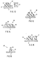
- the multi-stage elastomeric spring system 4 lies between the friction disks 2, 3 in the entire area of the rear or inner ring surfaces 11, 12.
- This spring system 4 consists of web springs 20 which are arranged regularly over the circumference of the ring surfaces 11, 12 and double cushion pads 30 located between them.
- the web springs 20 and the stop pads 30 are firmly connected to the friction disk 3, for example by gluing or vulcanization.
- the web springs 20 and the stop pads 30 are made of a suitable plastic or rubber.
- the web springs 20 are set softly and ensure a flat characteristic 25 with low spring force in the first part of the deflection path described later.
- the web springs 20 and stop pads 30 are designed in the form of radially arranged ribs.
- the web springs 20 serve primarily as spacers corresponding to their height 21 and initially guarantee a free space 31 between the stop pads 30 and the annular surface 11.
- the web springs 20 have a rectangular cross section with a wider base 22 for attachment to the annular surface 12.
- the webs 20 can also be mutually connected to the friction disks 2, 3.
- the stop pads 30 have a height 32 and a working width 33 and a linear contact surface 34. This contact surface 34 results from a convex section 35.
- the gently rising section 28 represents the elastic deformation of the webs 20 up to the stop of the flywheel-side ring surface 11 against the convex section 35 of the stop pads 30. A large distance from the friction disks 2, 3 is therefore covered with little force.
- This is followed, according to a second stage, by a progressive increase in the spring characteristic curve 25 by deformation of the stop pads 30, which are substantially larger in area, corresponding to the working width 33 and the web springs 20 corresponding to section 29. The entire travel is designated by 24.
- This spring characteristic 25 is typical of a motor vehicle clutch.
- the spring characteristic 25 can be varied by appropriate arrangement, shape, choice of material, variation of the Shore hardness, the web springs 20 and stop pads 30.
- the web 23 according to FIG. 4 is firmly connected to both friction disks 2, 3.
- the stop pads 30 can also have the same height 21 as the web springs 20. This requires, for example, a correspondingly tapered shape of the stop pads 30.
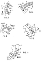
- integral pads 40, 50, 60, 70, 80 are vulcanized onto the friction disks 3.
- These integral pads 40 like the integral pads 50, 60, 70, 80, are provided on the entire circumference of the friction disk 3 in accordance with the division shown.
- the integral pads 40, 50, 60, 70, 80 have - just like the web spring 20 and the stop pad 30 - the two-stage spring characteristic 25 described in FIG. 6.
- the integral pads 40, 50, 60, 70, 80 are therefore a combination of bar spring 20 and stop pad 30.
- the pins 44, 52, 63, 73, 82 and 71 effect the section 28 (FIG. 6) and the base bodies 41, 51, 61, 72, 81 are decisive for the section 29.
- the manufacturing effort of the integral pads 40, 50, 60, 70, 80 is cheap.
- the variety of shapes means that it can be easily adapted to predetermined parameters, or by combining the integral pads 40, 50, 60, 70, 80 with a friction ring 1.
- the integral pads 40 have a wedge-shaped base body 41.
- the base body 41 is mutually vulcanized onto the friction disk 3.
- the short side 42 alternates with a long side 43 in the circumferential direction.
- the centrally arranged circular pin 44 is connected in one piece to the base body 41.
- the integral pads 50 on the friction disk 3 consist of glasses-shaped base bodies 51, each with two circular pins 52.
- the integral pads 60 have a gable-shaped curved base body 61 with a straight base 62 and the circular pin 63.
- the base bodies 61 are mutually vulcanized onto the friction ring 3 with their base 62.
- equilateral, triangular integral pads 70 and also triangular, equilateral web springs 71 are vulcanized onto the friction disks 3.
- the base bodies 72 of the integral cushions 70 have pins 73 that are symmetrical but smaller in shape than the base bodies 72.
- the position of the web springs 71 is in each case on a gap between the integral cushions 70, namely in accordance with half the division of the integral cushions 70.
- integral pads 80 with a circular base body 81 and small, likewise circular pins 82 are vulcanized onto the friction disk 3.
- the integral pads 80 are offset from one another on two circular rings 83, 84.
- the pins 44, 52, 63, 73, 82 and the web springs 71 define the axial spacing 21 between the friction disks 2, 3 in accordance with the steppers 20 and 23 according to FIGS. 1-4.
- the pins 44, 52, 63, 73, 82 or the web springs 71 can either rest only on the friction disk 2 or also be firmly connected to the latter.
- An elastomeric spring system 90 is designed as a cage 91 with bridges 89 and is firmly connected to the friction disk 3 at 94 outside the contact area 92. Webs 93, which are integrally connected to the stop pads 30, are vulcanized onto the friction disk 3.
- This spring system 90 can be connected to the friction disk 2 or 3 in a simple manner. It is even possible that this spring system 90 or spring cage 91 is loosely placed between the friction disks 2, 3 or lining halves and when riveting the friction disks 2, 3 to the lining carrier, e.g. B. is held on the torsion damper of a clutch disc only by clamping flags or rags attached to the spring system 90 between the or the pad tabs 6.
Landscapes
- Engineering & Computer Science (AREA)
- General Engineering & Computer Science (AREA)
- Mechanical Engineering (AREA)
- Mechanical Operated Clutches (AREA)
- Braking Arrangements (AREA)
Applications Claiming Priority (2)
| Application Number | Priority Date | Filing Date | Title |
|---|---|---|---|
| DE19621972 | 1996-05-31 | ||
| DE1996121972 DE19621972A1 (de) | 1996-05-31 | 1996-05-31 | Reibeinheit, betreffend eine Reibbelagfederung für Aggregate, wie Kupplungen oder Bremsen |
Publications (2)
| Publication Number | Publication Date |
|---|---|
| EP0810385A2 true EP0810385A2 (fr) | 1997-12-03 |
| EP0810385A3 EP0810385A3 (fr) | 1997-12-17 |
Family
ID=7795853
Family Applications (1)
| Application Number | Title | Priority Date | Filing Date |
|---|---|---|---|
| EP97108255A Withdrawn EP0810385A3 (fr) | 1996-05-31 | 1997-05-22 | Ensemble d'élément de friction à garnitures de progressivité par exemple pour embrayages ou freins |
Country Status (2)
| Country | Link |
|---|---|
| EP (1) | EP0810385A3 (fr) |
| DE (1) | DE19621972A1 (fr) |
Cited By (3)
| Publication number | Priority date | Publication date | Assignee | Title |
|---|---|---|---|---|
| GB2384034A (en) * | 2001-11-17 | 2003-07-16 | Ap Tmf Ltd | Clutch friction element with stops to limit cushioning |
| WO2013079875A1 (fr) * | 2011-12-01 | 2013-06-06 | Valeo Materiaux De Friction | Disque porte-garnitures a moyens de progressivite en materiau elastomere |
| WO2013093309A1 (fr) * | 2011-12-22 | 2013-06-27 | Valeo Materiaux De Friction | Dispositif de friction pour un embrayage |
Families Citing this family (1)
| Publication number | Priority date | Publication date | Assignee | Title |
|---|---|---|---|---|
| DE102018212123A1 (de) * | 2018-07-20 | 2020-01-23 | Zf Friedrichshafen Ag | Belaglamelle für ein Reibschaltelement |
Family Cites Families (4)
| Publication number | Priority date | Publication date | Assignee | Title |
|---|---|---|---|---|
| FR2658882A1 (fr) * | 1990-02-27 | 1991-08-30 | Valeo | Friction d'embrayage a faible inertie, notamment pour vehicule automobile. |
| DE59200227D1 (de) * | 1992-01-17 | 1994-07-14 | Textar Kupplungs Und Industrie | Kfz-Kupplungs-Mitnehmerscheibe. |
| DE4233406B4 (de) * | 1992-10-05 | 2005-01-27 | Zf Sachs Ag | Kupplungsscheibe mit einer Kunststoffnabe |
| DE4310978A1 (de) * | 1993-04-03 | 1994-10-06 | Diehl Gmbh & Co | Bauelement, bestehend aus Reibbelägen mit einer elastischen Zwischenschicht |
-
1996
- 1996-05-31 DE DE1996121972 patent/DE19621972A1/de not_active Withdrawn
-
1997
- 1997-05-22 EP EP97108255A patent/EP0810385A3/fr not_active Withdrawn
Cited By (7)
| Publication number | Priority date | Publication date | Assignee | Title |
|---|---|---|---|---|
| GB2384034A (en) * | 2001-11-17 | 2003-07-16 | Ap Tmf Ltd | Clutch friction element with stops to limit cushioning |
| WO2013079875A1 (fr) * | 2011-12-01 | 2013-06-06 | Valeo Materiaux De Friction | Disque porte-garnitures a moyens de progressivite en materiau elastomere |
| FR2983545A1 (fr) * | 2011-12-01 | 2013-06-07 | Valeo Materiaux De Friction | Disque porte-garnitures a moyens de progressivite en materiau elastomere |
| CN104024671A (zh) * | 2011-12-01 | 2014-09-03 | 瓦莱奥摩擦材料公司 | 具有用弹性体材料制成的渐进性部件的衬片座圆盘 |
| WO2013093309A1 (fr) * | 2011-12-22 | 2013-06-27 | Valeo Materiaux De Friction | Dispositif de friction pour un embrayage |
| FR2984979A1 (fr) * | 2011-12-22 | 2013-06-28 | Valeo Materiaux De Friction | Dispositif de friction pour un embrayage |
| CN104040204A (zh) * | 2011-12-22 | 2014-09-10 | 瓦莱奥摩擦材料公司 | 用于离合器的摩擦装置 |
Also Published As
| Publication number | Publication date |
|---|---|
| DE19621972A1 (de) | 1997-12-04 |
| EP0810385A3 (fr) | 1997-12-17 |
Similar Documents
| Publication | Publication Date | Title |
|---|---|---|
| DE69221505T2 (de) | Dämpfer mit oberflächenwirkung | |
| DE69010669T2 (de) | Reibbelag und belagträgerscheibe. | |
| DE69101404T2 (de) | Torsionsdämpfende Vorrichtung für Reibplatte einer Kraftfahrzeugkupplung. | |
| DE9212203U1 (de) | Kupplungsscheibe mit radial elastischem Kunststoffring | |
| DE3242448A1 (de) | Riemenscheibe eines stufenlosen regelgetriebes | |
| DE19901043A1 (de) | Kupplungsscheibe für eine Kraftfahrzeug-Reibungskupplung | |
| DE3227004A1 (de) | Kupplungsscheibe mit reibungsdaempfer und blattfedern | |
| DE10148681B4 (de) | Bremsscheibe für eine Scheibenbremse | |
| EP0810385A2 (fr) | Ensemble d'élément de friction à garnitures de progressivité par exemple pour embrayages ou freins | |
| EP0552387A1 (fr) | Disque mené d'embrayage pour véhicule automobile | |
| DE69613198T2 (de) | Drehschwingungsdämpfer,insbesondere für Kraftfahrzeuge | |
| DE60001297T2 (de) | Elastische Kupplung für koaxiale Wellen | |
| DE102024129947A1 (de) | Schwingungsdämpfer | |
| DE69618099T2 (de) | Reibungskupplungsscheibe, insbesondere für Kraftfahrzeuge | |
| DE69610890T2 (de) | Trockenreibungskupplung für Kraftfahrzeuge | |
| DE69200599T2 (de) | Reibungsscheibe für Trockenkupplung. | |
| EP0615075A1 (fr) | Amortisseur d'oscillations rotatives en particulier pour le train d'entraînement d'un véhicule à moteur | |
| DE10038410A1 (de) | Kupplungsscheibe | |
| DE19529074C1 (de) | Kupplungsscheibe mit wechselseitig gewölbten Belagfederfahnen | |
| DE3218955A1 (de) | Daempfungsscheibe | |
| DE202010017795U1 (de) | Antriebsscheibe mit Schwingungsdämpfermitteln | |
| DE19711400A1 (de) | Radialwellendichtring | |
| DE4310978A1 (de) | Bauelement, bestehend aus Reibbelägen mit einer elastischen Zwischenschicht | |
| DE3507076A1 (de) | Haltevorrichtung fuer eine membranfeder | |
| EP1966501A1 (fr) | Palier pivotant annulaire utilise dans un element ressort de levier de type ressort a disques et dispositif de couplage |
Legal Events
| Date | Code | Title | Description |
|---|---|---|---|
| PUAI | Public reference made under article 153(3) epc to a published international application that has entered the european phase |
Free format text: ORIGINAL CODE: 0009012 |
|
| PUAL | Search report despatched |
Free format text: ORIGINAL CODE: 0009013 |
|
| AK | Designated contracting states |
Kind code of ref document: A2 Designated state(s): DE ES FR GB IT NL |
|
| AK | Designated contracting states |
Kind code of ref document: A3 Designated state(s): DE ES FR GB IT NL |
|
| 17P | Request for examination filed |
Effective date: 19971114 |
|
| 17Q | First examination report despatched |
Effective date: 19980317 |
|
| GRAG | Despatch of communication of intention to grant |
Free format text: ORIGINAL CODE: EPIDOS AGRA |
|
| GRAG | Despatch of communication of intention to grant |
Free format text: ORIGINAL CODE: EPIDOS AGRA |
|
| GRAH | Despatch of communication of intention to grant a patent |
Free format text: ORIGINAL CODE: EPIDOS IGRA |
|
| STAA | Information on the status of an ep patent application or granted ep patent |
Free format text: STATUS: THE APPLICATION IS DEEMED TO BE WITHDRAWN |
|
| 18D | Application deemed to be withdrawn |
Effective date: 19991027 |