EP0810392A2 - Dispositif de commande - Google Patents
Dispositif de commande Download PDFInfo
- Publication number
- EP0810392A2 EP0810392A2 EP97107425A EP97107425A EP0810392A2 EP 0810392 A2 EP0810392 A2 EP 0810392A2 EP 97107425 A EP97107425 A EP 97107425A EP 97107425 A EP97107425 A EP 97107425A EP 0810392 A2 EP0810392 A2 EP 0810392A2
- Authority
- EP
- European Patent Office
- Prior art keywords
- control device
- adjusting lever
- lever
- link
- rocker
- Prior art date
- Legal status (The legal status is an assumption and is not a legal conclusion. Google has not performed a legal analysis and makes no representation as to the accuracy of the status listed.)
- Granted
Links
Images



Classifications
-
- G—PHYSICS
- G05—CONTROLLING; REGULATING
- G05G—CONTROL DEVICES OR SYSTEMS INSOFAR AS CHARACTERISED BY MECHANICAL FEATURES ONLY
- G05G5/00—Means for preventing, limiting or returning the movements of parts of a control mechanism, e.g. locking controlling member
- G05G5/06—Means for preventing, limiting or returning the movements of parts of a control mechanism, e.g. locking controlling member for holding members in one or a limited number of definite positions only
-
- F—MECHANICAL ENGINEERING; LIGHTING; HEATING; WEAPONS; BLASTING
- F16—ENGINEERING ELEMENTS AND UNITS; GENERAL MEASURES FOR PRODUCING AND MAINTAINING EFFECTIVE FUNCTIONING OF MACHINES OR INSTALLATIONS; THERMAL INSULATION IN GENERAL
- F16H—GEARING
- F16H59/00—Control inputs to control units of change-speed- or reversing-gearings for conveying rotary motion
- F16H59/02—Selector apparatus
-
- F—MECHANICAL ENGINEERING; LIGHTING; HEATING; WEAPONS; BLASTING
- F16—ENGINEERING ELEMENTS AND UNITS; GENERAL MEASURES FOR PRODUCING AND MAINTAINING EFFECTIVE FUNCTIONING OF MACHINES OR INSTALLATIONS; THERMAL INSULATION IN GENERAL
- F16H—GEARING
- F16H59/00—Control inputs to control units of change-speed- or reversing-gearings for conveying rotary motion
- F16H59/02—Selector apparatus
- F16H59/0278—Constructional features of the selector lever, e.g. grip parts, mounting or manufacturing
- F16H2059/0282—Lever handles with lock mechanisms, e.g. for allowing selection of reverse gear or releasing lever from park position
-
- F—MECHANICAL ENGINEERING; LIGHTING; HEATING; WEAPONS; BLASTING
- F16—ENGINEERING ELEMENTS AND UNITS; GENERAL MEASURES FOR PRODUCING AND MAINTAINING EFFECTIVE FUNCTIONING OF MACHINES OR INSTALLATIONS; THERMAL INSULATION IN GENERAL
- F16H—GEARING
- F16H61/00—Control functions within control units of change-speed- or reversing-gearings for conveying rotary motion ; Control of exclusively fluid gearing, friction gearing, gearings with endless flexible members or other particular types of gearing
- F16H61/24—Providing feel, e.g. to enable selection
- F16H2061/242—Mechanical shift gates or similar guiding means during selection and shifting
Definitions
- the invention relates to a control device, in particular for agricultural or construction vehicles, according to the preamble of claim 1.
- Such control devices with an actuating lever are known, for example, from the motor vehicle sector, wherein the actuating lever can be used to select a gear or driving stage of a transmission, for which purpose the actuating lever can be moved in at least one axis between positions in a link.
- these control devices are simple in construction, they do not meet the requirements for application-specific areas of application.
- control device Accordingly, at least one advantage being that a movement of the actuating lever in one direction (for example a main axis) is converted into an actuating movement (for example an actuating linkage) in a direction transverse to the main axis Axis.
- actuating movement for example an actuating linkage
- Another advantage is that by means of the sliding sleeve, which can be moved up and down on the adjusting lever and possibly rotated, the adjusting lever can be easily fixed or freely moved in a predeterminable area delimited by the link.
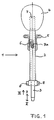
- FIG. 1 shows an adjusting lever with which the control device according to the invention can be operated.
- An adjusting lever designated by the reference number 1 essentially consists of a guide tube 2, in which a rod 3 is arranged and supported in a longitudinally displaceable manner.
- the adjusting lever 1 has a knob 4, below which a displaceable adjusting sleeve 5 is arranged coaxially around the guide tube 2.
- the adjusting sleeve 5 is connected to the rod 3 by means of a radially oriented pin 3a, so that by pulling or releasing the adjusting sleeve 5, simultaneous support of the hand of the operator on the knob 4, a longitudinal displacement of the rod 3 or the pin 3a in the recess 6 in the two directions, which are designated I and II, is possible.
- the longitudinal displacement of the rod 3 takes place against a pretension, which is realized according to FIG. 1 by a compression spring 7 arranged in the knob 4.
- the rod 3 can be displaced longitudinally in the direction I.
- a further displacement of the rod 3 in the direction of the knob 4 is possible, which is indicated by III.
- the adjusting sleeve 5 is rotated, for example, approximately 90 ° in the guide tube 2, the connection between the rod 3 and the adjusting sleeve 5 then reaching a recess in the guide tube 2, which is another Movement of the rod 3 in the direction III allowed.
- the recess in the Guide tube 2 it is possible to lock the rod 3 in the individual positions or to move it back to its starting position due to the pretension.
- a structurally simpler and therefore less expensive solution for the longitudinal displacement and locking of the adjusting sleeves 5 can be seen in the fact that one or more grooves are arranged on the surface of the guide tube 2, in which part of the adjusting sleeve 5 can engage.
- the adjusting lever 1 is pivotally mounted around the journal 8.
- FIG. 2 shows a longitudinal section through the control device according to the invention.
- the control lever 1, indicated by the guide tube 2 can be moved in two directions and any combination of these two directions, it is also conceivable to control the control lever 1 about a single axis, characterized by the bearing pin 8 to deflect into just one plane.
- the control device shown in FIG. 2 is used, which is arranged in a console 9 of a vehicle, for example within easy reach of the operator of the vehicle.
- Support elements 10 and 11 are arranged below the console 9 or as a component thereof, and are arranged in one piece or divided on the console 9, for example by means of a screw connection.
- the carrier elements 11 receive a rocker arm 12 which is approximately U-shaped in cross section and has bearing journals on its legs, similar to the bearing journals 8 of the actuating lever 1.
- the rocker arm 12 can thus be deflected in one plane by means of the actuating lever 1.
- a further mounting is arranged in the rocker arm 12 itself, which receives the adjusting lever 1 and allows the adjusting lever 1 to be deflected into a transverse plane. Because of this gimbal mounting and suspension of the control lever 1 can be carried out with these deflections in one plane and in a transverse plane and in combinations thereof.
- Transmission elements 13 are arranged on the actuating lever 1, while further transmission elements 14 are arranged on the rocker arm 12.
- the transmission elements 13 are designed such that their movement is transmitted to a tendon arranged in a Bowden cable 15, so that the Chord 16 also performs a movement to the right or left when viewing FIG. 2.
- the transmission elements 14 are designed in such a way that when the adjusting lever 1 is deflected out of FIG. 2 or into it, a further chord arranged in a further Bowden cable 17 forms a movement directed transversely to the deflection, that is to say in the same direction or opposite to it the tendon 16.
- a link 19 is arranged below the rocker 12, that is to say in the end region of the rod 3, the adjusting lever 1 or the rod 3 being deflectable and / or fixable depending on the link 19.
- there is at least one guide level 20 which is supplemented by a further level 21, the levels 20 and / or 21 being configured at least as a longitudinal guide (possibly also as a transverse guide or as a surface).
- the rod 3 is in a position such that its end is on the guide plane 20 and can slide along this plane 20. A stepless deflection of the actuating lever 1 is thus possible. If a fixing (locking) is desired, the rod 3 can be displaced longitudinally by longitudinal displacement by means of a corresponding longitudinal displacement of the adjusting sleeve 5 and / or a corresponding rotation of the adjusting sleeve 5 in the direction II, so that the end of the stand 3 engages in one of the bores 22 and thus the control lever 1 is locked. This enables a permanent function to be switched on or off, for example.
- Figure 2a shows a longitudinal configuration of the backdrop 19, three-dimensional configurations are also conceivable, the one Map-like setting of a function or functions guaranteed.
- the backdrop 19 or a flat backdrop 19 is designed in the shape of a circular arc or pillow in order to understand the pivoting movement of the actuating lever 1 through this configuration.
- a structurally simpler design consists of a straight-line or area-like design.
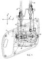
- FIG. 3 shows, as a supplement, a cross section through the control device according to the invention, in which case the realization of the transmission elements 14 by means of articulated rods and ball heads is visible. Furthermore, it can be seen that the rocker arm 12 is arranged in a bearing 23, the structure of which is shown and described in FIG. 6.
- FIG. 4 shows a plan view of the adjusting device according to the invention, it being shown that an adjusting lever 1 is arranged in the console 9, which can be adjusted both in the X and Y direction and in any combination of these two directions.
- the deflection of the actuating lever 1 is transmitted in the same direction (when looking at FIG. 4 upwards or downwards).
- FIG. 4 also shows that the transmission elements 13 and 14 are initially followed by push rods 24 and 25, which are followed by the Bowden cables 15 and 17. It is also conceivable to use only Bowden cables or only push rods.
- a pin 26 is arranged within the rocker arm 12, through which the adjusting lever 1 is guided.
- the bolt 26 is rotatably mounted in the rocker arm 12 and thus (when viewing FIG. 4) allows the control lever 1 to be deflected to the right or to the left.
- the rocker 12 can be deflected upwards or downwards by a corresponding deflection of the adjusting lever 1 when viewing FIG. 4.
- Figure 5 shows an inserted control lever with which simple assembly is possible.
- the bolt 26 has the bore 27, which has a slightly larger diameter or approximately the same diameter as the guide tube 2. Furthermore, it also has a bore 27a perpendicular to it or, in the case of thicker bolts, two blind bores.
- Claws are located on the guide tube 2 28, which are designed, for example, as a plastic injection-molded part and are firmly connected to the guide tube 2 by gluing or pressing on.
- the claws have two projections 28a on their inner sides, which are assigned to the bore 27a.
- FIG. 6 shows a mounting of the actuating lever 1 or the rocker arm 12, a longitudinal slot 29 with a subsequent bore 30 having a larger diameter than the bearing journal 8 being provided in the support element 10 or 11 of the bracket 9.
- the bearing pin 8 fixed and stored at the same time, lubrication can also take place in this area. It is also conceivable to produce the sleeve 31 from a material that has lubricating properties (for example plastic). It is also conceivable that the sleeve 31 is a ball bearing or the like. To fix the sleeve 31, the journal has in its end region a circumferential groove which receives a spring ring. It is also conceivable to fix the sleeve 3 by means of a pin or cotter pin which is guided vertically through the bearing journal 8. It is also conceivable that a collar is arranged on the sleeve 31, which abuts the carrier elements 10 and 11, respectively.
- the control lever 1 can then be used to manually control, trigger, change or fix at least one function or also a plurality of functions.
Landscapes
- Engineering & Computer Science (AREA)
- General Engineering & Computer Science (AREA)
- Mechanical Engineering (AREA)
- Physics & Mathematics (AREA)
- General Physics & Mathematics (AREA)
- Automation & Control Theory (AREA)
- Mechanical Control Devices (AREA)
- Massaging Devices (AREA)
- Valve Device For Special Equipments (AREA)
- Iron Core Of Rotating Electric Machines (AREA)
- Lifting Devices For Agricultural Implements (AREA)
- Switches With Compound Operations (AREA)
Applications Claiming Priority (2)
| Application Number | Priority Date | Filing Date | Title |
|---|---|---|---|
| DE19621392 | 1996-05-28 | ||
| DE19621392A DE19621392A1 (de) | 1996-05-28 | 1996-05-28 | Steuereinrichtung |
Publications (3)
| Publication Number | Publication Date |
|---|---|
| EP0810392A2 true EP0810392A2 (fr) | 1997-12-03 |
| EP0810392A3 EP0810392A3 (fr) | 1999-06-09 |
| EP0810392B1 EP0810392B1 (fr) | 2003-02-12 |
Family
ID=7795502
Family Applications (1)
| Application Number | Title | Priority Date | Filing Date |
|---|---|---|---|
| EP97107425A Expired - Lifetime EP0810392B1 (fr) | 1996-05-28 | 1997-05-06 | Dispositif de commande |
Country Status (3)
| Country | Link |
|---|---|
| EP (1) | EP0810392B1 (fr) |
| AT (1) | ATE232585T1 (fr) |
| DE (2) | DE19621392A1 (fr) |
Family Cites Families (8)
| Publication number | Priority date | Publication date | Assignee | Title |
|---|---|---|---|---|
| US2964964A (en) * | 1959-04-10 | 1960-12-20 | Gen Motors Corp | Control mechanism |
| US4103559A (en) * | 1977-03-09 | 1978-08-01 | Caterpillar Tractor Co. | Detented manual actuator for a multifunction system |
| US4328712A (en) * | 1980-01-24 | 1982-05-11 | Jsj Corporation | Lockout for gimbal-type automotive transmission gear shifter |
| US4338828A (en) * | 1980-05-21 | 1982-07-13 | Borg-Warner Corporation | Transmission shift control guide and detent apparatus |
| DE3438899A1 (de) * | 1984-10-24 | 1986-04-24 | Robert Bosch Gmbh, 7000 Stuttgart | Bremsventil, insbesondere feststellbremsventil fuer nutzfahrzeug-bremsanlagen |
| DE3809043C2 (de) * | 1988-03-18 | 1997-05-07 | Meyra Wilhelm Meyer Gmbh & Co | Steuereinrichtung für elektrische Rollstühle oder dergleichen |
| US4912997A (en) * | 1989-06-02 | 1990-04-03 | Chrysler Corporation | Electric shift selector mechanism for transmission |
| JPH0687343A (ja) * | 1992-09-07 | 1994-03-29 | Jidosha Kiki Co Ltd | チェンジレバーユニット |
-
1996
- 1996-05-28 DE DE19621392A patent/DE19621392A1/de not_active Withdrawn
-
1997
- 1997-05-06 EP EP97107425A patent/EP0810392B1/fr not_active Expired - Lifetime
- 1997-05-06 AT AT97107425T patent/ATE232585T1/de not_active IP Right Cessation
- 1997-05-06 DE DE59709296T patent/DE59709296D1/de not_active Expired - Fee Related
Also Published As
| Publication number | Publication date |
|---|---|
| EP0810392B1 (fr) | 2003-02-12 |
| EP0810392A3 (fr) | 1999-06-09 |
| DE59709296D1 (de) | 2003-03-20 |
| ATE232585T1 (de) | 2003-02-15 |
| DE19621392A1 (de) | 1997-12-04 |
Similar Documents
| Publication | Publication Date | Title |
|---|---|---|
| EP0731885B1 (fr) | Dispositif de changement de vitesse | |
| DE3128752C2 (de) | Wendeschalter für Kraftfahrzeuge | |
| DE19882218B4 (de) | Getriebe mit einer Zentralschaltwelle | |
| DE4221762A1 (de) | Schalthebellagerung | |
| EP0373368A1 (fr) | Dispositif pour verrouiller un levier de changement de vitesse dans une position correspondant à un rapport ou d'une programmation de rapports dépendant d'une pédale de frein | |
| DE4406598C2 (de) | Schalteinrichtung für ein selbsttätig schaltendes Wechselgetriebe mit einer mechanischen Sperre für den Rückwärtsgang in einem Kraftfahrzeug | |
| EP0933563A1 (fr) | Dispositif de changement de vitesses pour transmission de vitesse de véhicule | |
| DE102005001818B4 (de) | Schaltvorrichtung für ein Automatikgetriebe eines Kraftfahrzeuges | |
| DE60014277T2 (de) | Schaltgabel für Getriebe eines Kraftfahrzeuges | |
| EP0936384A1 (fr) | Dispositif d'actionnement d'une boíte de vitesses de véhicule | |
| DE1725024B2 (de) | Hebel-Steuervorrichtung | |
| DE3829109A1 (de) | Elektrischer schalter, insbesondere lenstockschalter fuer kratfahrzeuge | |
| DE19633948A1 (de) | Wähleinrichtung für ein Automatikgetriebe eines Kraftfahrzeugs | |
| DE102005060933B3 (de) | Wählhebel, insbesondere für ein Kraftfahrzeug | |
| EP1531290B1 (fr) | Dispositif de sélection de vitesse | |
| DE102007045653A1 (de) | Betätigungseinrichtung für ein Wechselgetriebe eines Kraftfahrzeuges | |
| DE69602687T2 (de) | Steuerhebelanordnung mit verbesserter Positionsarretierung | |
| DE102007027753A1 (de) | Zugmittelmechanismus, insbesondere für verstellbare Fahrzeugsitze | |
| DE69801608T2 (de) | Vorrichtung zum Schalten eines Gangwechselgetriebes eines Kraftfahrzeuges | |
| EP0611425A1 (fr) | Systeme de changement de vitesse pour la commande de boites de vitesses multi-etagees de vehicules automobiles. | |
| EP0489886B1 (fr) | Commutateur electrique, notamment commutateur fixe a la colonne de direction de vehicules a moteur | |
| DE102004033446A1 (de) | Schaltmodul | |
| DE3103698A1 (de) | Mechanische verriegelung | |
| DE60203864T2 (de) | Hebelschalter für Fahrzeuge | |
| DE4034256A1 (de) | Neigungseinstellbarer scheinwerfer |
Legal Events
| Date | Code | Title | Description |
|---|---|---|---|
| PUAI | Public reference made under article 153(3) epc to a published international application that has entered the european phase |
Free format text: ORIGINAL CODE: 0009012 |
|
| AK | Designated contracting states |
Kind code of ref document: A2 Designated state(s): AT DE FR GB IT |
|
| RAP1 | Party data changed (applicant data changed or rights of an application transferred) |
Owner name: SAME DEUTZ-FAHR S.P.A. |
|
| PUAL | Search report despatched |
Free format text: ORIGINAL CODE: 0009013 |
|
| AK | Designated contracting states |
Kind code of ref document: A3 Designated state(s): AT DE FR GB IT |
|
| 17P | Request for examination filed |
Effective date: 19990709 |
|
| 17Q | First examination report despatched |
Effective date: 20010228 |
|
| GRAG | Despatch of communication of intention to grant |
Free format text: ORIGINAL CODE: EPIDOS AGRA |
|
| GRAG | Despatch of communication of intention to grant |
Free format text: ORIGINAL CODE: EPIDOS AGRA |
|
| GRAH | Despatch of communication of intention to grant a patent |
Free format text: ORIGINAL CODE: EPIDOS IGRA |
|
| GRAH | Despatch of communication of intention to grant a patent |
Free format text: ORIGINAL CODE: EPIDOS IGRA |
|
| GRAA | (expected) grant |
Free format text: ORIGINAL CODE: 0009210 |
|
| RAP1 | Party data changed (applicant data changed or rights of an application transferred) |
Owner name: SAME DEUTZ-FAHR GROUP S.P.A. |
|
| AK | Designated contracting states |
Designated state(s): AT DE FR GB IT |
|
| PG25 | Lapsed in a contracting state [announced via postgrant information from national office to epo] |
Ref country code: IT Free format text: LAPSE BECAUSE OF FAILURE TO SUBMIT A TRANSLATION OF THE DESCRIPTION OR TO PAY THE FEE WITHIN THE PRE;WARNING: LAPSES OF ITALIAN PATENTS WITH EFFECTIVE DATE BEFORE 2007 MAY HAVE OCCURRED AT ANY TIME BEFORE 2007. THE CORRECT EFFECTIVE DATE MAY BE DIFFERENT FROM THE ONE RECORDED.SCRIBED TIME-LIMIT Effective date: 20030212 Ref country code: FR Free format text: LAPSE BECAUSE OF FAILURE TO SUBMIT A TRANSLATION OF THE DESCRIPTION OR TO PAY THE FEE WITHIN THE PRESCRIBED TIME-LIMIT Effective date: 20030212 |
|
| REG | Reference to a national code |
Ref country code: GB Ref legal event code: FG4D Free format text: NOT ENGLISH |
|
| REF | Corresponds to: |
Ref document number: 59709296 Country of ref document: DE Date of ref document: 20030320 Kind code of ref document: P |
|
| PG25 | Lapsed in a contracting state [announced via postgrant information from national office to epo] |
Ref country code: AT Free format text: LAPSE BECAUSE OF NON-PAYMENT OF DUE FEES Effective date: 20030506 |
|
| PG25 | Lapsed in a contracting state [announced via postgrant information from national office to epo] |
Ref country code: GB Free format text: LAPSE BECAUSE OF NON-PAYMENT OF DUE FEES Effective date: 20030512 |
|
| GBT | Gb: translation of ep patent filed (gb section 77(6)(a)/1977) |
Effective date: 20030425 |
|
| PG25 | Lapsed in a contracting state [announced via postgrant information from national office to epo] |
Ref country code: DE Free format text: LAPSE BECAUSE OF NON-PAYMENT OF DUE FEES Effective date: 20031202 |
|
| PLBE | No opposition filed within time limit |
Free format text: ORIGINAL CODE: 0009261 |
|
| STAA | Information on the status of an ep patent application or granted ep patent |
Free format text: STATUS: NO OPPOSITION FILED WITHIN TIME LIMIT |
|
| GBPC | Gb: european patent ceased through non-payment of renewal fee |
Effective date: 20030512 |
|
| EN | Fr: translation not filed | ||
| 26N | No opposition filed |
Effective date: 20031113 |