EP0810398A2 - Robinets-vannes électriques - Google Patents
Robinets-vannes électriques Download PDFInfo
- Publication number
- EP0810398A2 EP0810398A2 EP97106395A EP97106395A EP0810398A2 EP 0810398 A2 EP0810398 A2 EP 0810398A2 EP 97106395 A EP97106395 A EP 97106395A EP 97106395 A EP97106395 A EP 97106395A EP 0810398 A2 EP0810398 A2 EP 0810398A2
- Authority
- EP
- European Patent Office
- Prior art keywords
- sealing
- valve according
- slide
- actuator
- actuating
- Prior art date
- Legal status (The legal status is an assumption and is not a legal conclusion. Google has not performed a legal analysis and makes no representation as to the accuracy of the status listed.)
- Granted
Links
- 238000007789 sealing Methods 0.000 claims abstract description 55
- 238000005452 bending Methods 0.000 claims description 9
- 238000013022 venting Methods 0.000 abstract 2
- 230000006870 function Effects 0.000 description 13
- 210000002105 tongue Anatomy 0.000 description 6
- 239000012790 adhesive layer Substances 0.000 description 1
- 238000000418 atomic force spectrum Methods 0.000 description 1
- 239000011248 coating agent Substances 0.000 description 1
- 238000000576 coating method Methods 0.000 description 1
- 239000000446 fuel Substances 0.000 description 1
- 238000002347 injection Methods 0.000 description 1
- 239000007924 injection Substances 0.000 description 1
- 238000004519 manufacturing process Methods 0.000 description 1
Images
Classifications
-
- F—MECHANICAL ENGINEERING; LIGHTING; HEATING; WEAPONS; BLASTING
- F16—ENGINEERING ELEMENTS AND UNITS; GENERAL MEASURES FOR PRODUCING AND MAINTAINING EFFECTIVE FUNCTIONING OF MACHINES OR INSTALLATIONS; THERMAL INSULATION IN GENERAL
- F16K—VALVES; TAPS; COCKS; ACTUATING-FLOATS; DEVICES FOR VENTING OR AERATING
- F16K31/00—Actuating devices; Operating means; Releasing devices
- F16K31/004—Actuating devices; Operating means; Releasing devices actuated by piezoelectric means
- F16K31/007—Piezoelectric stacks
- F16K31/008—Piezoelectric stacks for sliding valves
-
- F—MECHANICAL ENGINEERING; LIGHTING; HEATING; WEAPONS; BLASTING
- F16—ENGINEERING ELEMENTS AND UNITS; GENERAL MEASURES FOR PRODUCING AND MAINTAINING EFFECTIVE FUNCTIONING OF MACHINES OR INSTALLATIONS; THERMAL INSULATION IN GENERAL
- F16K—VALVES; TAPS; COCKS; ACTUATING-FLOATS; DEVICES FOR VENTING OR AERATING
- F16K3/00—Gate valves or sliding valves, i.e. cut-off apparatus with closing members having a sliding movement along the seat for opening and closing
- F16K3/02—Gate valves or sliding valves, i.e. cut-off apparatus with closing members having a sliding movement along the seat for opening and closing with flat sealing faces; Packings therefor
- F16K3/16—Gate valves or sliding valves, i.e. cut-off apparatus with closing members having a sliding movement along the seat for opening and closing with flat sealing faces; Packings therefor with special arrangements for separating the sealing faces or for pressing them together
- F16K3/18—Gate valves or sliding valves, i.e. cut-off apparatus with closing members having a sliding movement along the seat for opening and closing with flat sealing faces; Packings therefor with special arrangements for separating the sealing faces or for pressing them together by movement of the closure members
-
- F—MECHANICAL ENGINEERING; LIGHTING; HEATING; WEAPONS; BLASTING
- F16—ENGINEERING ELEMENTS AND UNITS; GENERAL MEASURES FOR PRODUCING AND MAINTAINING EFFECTIVE FUNCTIONING OF MACHINES OR INSTALLATIONS; THERMAL INSULATION IN GENERAL
- F16K—VALVES; TAPS; COCKS; ACTUATING-FLOATS; DEVICES FOR VENTING OR AERATING
- F16K31/00—Actuating devices; Operating means; Releasing devices
- F16K31/02—Actuating devices; Operating means; Releasing devices electric; magnetic
Definitions
- the invention relates to a valve according to the preamble of claim 1.
- Valves for a wide variety of applications are known in practice. They have at least two connections and a slide which can move back and forth between at least two switching positions, the slide sealing at least one connection in one switching position and releasing it in the other switching position. There are also actuating means for performing the actuating function and sealing means for performing the sealing function of the slide.
- US Pat. No. 4,678,000 discloses an electromagnetic injection valve for fuels, a slide in one switching position releasing the connection between two connections and closing it in the other switching position.
- an electromagnetic actuating device By actuating an electromagnetic actuating device, the slide is brought into the closed position, the front end of which comes into contact with a corresponding sealing seat.
- the electromagnetic actuating device thus generates the positioning force on the one hand and the sealing force on the slide on the other.
- the slide In the closed position, the slide is clamped by means of a piezo element.
- the electromagnetic actuating device is of relatively large design, since on the one hand it has to produce a relatively large actuating travel of the slide and, on the other hand, a relatively large sealing force in the closed position.
- the invention is therefore based on the object of further developing the valve so that it can be switched more effectively and reliably.
- the characterizing feature of claim 1 in that the actuating means have an actuating actuator and the sealing means have a sealing actuator which can be controlled separately from one another.
- the functions of "setting” and “sealing" the slide to achieve the valve function can be achieved via several separate actuators.
- Each actuator can be optimally designed for its function, especially with regard to travel and positioning force.
- the actuating actuator is required to have a comparatively large actuating path with a low actuating force, whereas the sealing actuator has reverse requirements, namely a small actuating path and large actuating force.
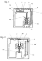
- a slide 4 is arranged to move back and forth between two switching positions, the slide closing the exhaust air connection 3 in the switching position shown and establishing the connection between the device connection 1 and pressure connection 2 and releasing the exhaust air connection 3 in the other switching position and in this way a connection between Provides device connection 1 and exhaust air connection 3.
- actuating means for performing the actuating function are also connected, which are formed by an actuating actuator 5a and an elastic element, in particular a first spring element 5b.
- sealing means are provided which comprise a sealing actuator 6a and a second spring element 6b.
- both the actuating actuator 5a and the sealing actuator 6a are formed by a piezoelectric bending tongue clamped on one side.
- the actuator 5a is excited by appropriate voltage application so that it counteracts the slide 4 the force of the spring element 5b shifts to the left.
- the sealing actuator 6a is excited in such a way that it cancels the sealing force exerted on the slide by the second spring element 6b.
- the reset of the sealing actuator 6a and thus the exertion of the sealing force takes place after adjustment of the slide 4 by the second spring element 6b.
- the two actuators 5a, 6a do not have to transmit any further forces to the slide. This has the great advantage that no so-called "creep” can occur in the actuators formed by the bending tongues. This creep can occur in particular when a bending tongue has to be deflected for a long time, since the adhesive layer in the actuator may then slide off.
- the two end positions of the slide 4 are expediently limited by two stops 7, 8.
- the sealing actuator 6a In contrast to the actuating actuator 5a, the sealing actuator 6a only requires a short actuating path. In order to be able to compensate for any manufacturing tolerances, the spring force of the second spring element 6b is set by an adjusting screw 9.
- the slide 4 has a seal 4a which comes into operative connection with a corresponding connection, in particular an elastic coating, which is provided on one of the side surfaces of the slide arranged in the direction of movement of the slide.
- the second exemplary embodiment shown in FIG. 2 again represents a 3/2-way valve, but the exhaust air connection 3 'transversely to the device connection 1 and Pressure port 2 is arranged on another side of the valve.
- the slider 4 can in turn be moved back and forth between two positions by an actuating actuator 5a.
- the sealing means are formed by a second spring element 6b and a sealing actuator 6'a, the sealing actuator 6'a being provided as an electromagnetically actuated armature.
- the sealing actuator 6'a is thus first actuated in order to cancel the spring force of the second spring element 6b, so that the actuating actuator 5a can then be controlled.
- the actuating actuator 5a is in turn formed by a piezoelectric bending tongue clamped on one side, the resetting of the slide 4 being achieved by the spring force present in the actuating actuator 5a.
- the "creep" described above may occur in this embodiment.
- the exhaust air connection 3 ' is arranged perpendicular to the device connection 1 and to the pressure connection 2 in the exemplary embodiment shown.
- This has the advantage that the system pressure, which presses the slide from the inside onto the exhaust air connection 3 ', only acts when the slide 4 has not yet been moved. Even if the slide is lifted slightly from the exhaust air connection 3 ', the pressure and thus the force falls on the actuating actuator 5a.
- This force curve accommodates the actuating actuator 5a, which is designed as a piezoelectric bending tongue and can achieve the greatest force with minimal deflection.
- the exemplary embodiment according to FIG. 1 has the disadvantage over that of FIG. 2 that the compressive force affects the Exhaust air connection 3 acts as a normal force on the frictional force of the slide 4 and this in addition on a long way.
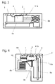
- the third exemplary embodiment shown in FIG. 3 shows a 2/2-way valve, in which only one device connection 1 and one pressure connection 2 are provided, the slide 4 releasing the pressure connection 2 in one switching position and closing it in the other switching position.
- the actuating movement of the slide 4 is achieved here by an electromagnetic actuating actuator 5'a, which in turn interacts with a first spring element 5b.
- the sealing force is generated by a piezoelectric bending strip 6a, which is applied on both sides to increase its actuating force.
- the sealing actuator 6a works against the slide 4 without an additional spring element.
- the necessary spring force can then be generated, for example, by prestressing the sealing actuator.
- the fourth exemplary embodiment shown in FIG. 4 again corresponds in terms of its external connections to the 3/2-way valve shown in FIG.
- the actuating means are formed by an actuating actuator 5a designed as a piezoelectric bending tongue and a first spring element 5b.
- the sealing force is generated by a spring element 6b, while this sealing force is canceled by a sealing actuator 6a designed as a stacked piezo.
- a lever 10 is used to increase the deflection of the sealing actuator 6a.
- the slide 4 'shown has a bore 4'b through which the medium is guided in the open state, i.e. when the device port 1 is connected to the pressure port 2.
- the particular advantage of this design of the slide 4 is that there are small pressure-filled volumes in the valve, so that the time required to build up pressure is low.
- the elements shown in the individual exemplary embodiments are interchangeable.
- the peculiarity of all exemplary embodiments is that the function "set" and the function "seal" is carried out by two separate actuators. While the actuating actuator needs the longest possible travel and the sealing actuator the greatest possible sealing force, each actuator can be optimally designed for its function. By the actuating actuator and the sealing actuator acting in different directions on the slider 4, 4 ', the functions can also be cleanly separated from one another. In some cases, in addition to the function of sealing, the sealing actuator also exerts a clamping function on the slide.
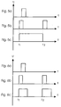
- 5a to 5c show three curves, the control of the entire valve being shown from the outside in FIG. 5c.
- 5a shows the actuation of the actuating actuator and 5b the actuation of the sealing actuator.
- the control voltage U is shown versus time t.
- the sealing actuator is first switched at time t 1 .
- the actuator is activated at the same time or a little later.
- an electrical pulse is used to switch between the "open” and “closed” positions.
- the last position of the valve (open or closed) must be buffered in a memory.
- the actuators are either activated to open the valve or only the sealing actuator is switched to close, depending on the memory content.
Landscapes
- Engineering & Computer Science (AREA)
- General Engineering & Computer Science (AREA)
- Mechanical Engineering (AREA)
- Electrically Driven Valve-Operating Means (AREA)
- Multiple-Way Valves (AREA)
- Magnetically Actuated Valves (AREA)
- Sliding Valves (AREA)
Applications Claiming Priority (2)
| Application Number | Priority Date | Filing Date | Title |
|---|---|---|---|
| DE19621796A DE19621796A1 (de) | 1996-05-30 | 1996-05-30 | Ventil |
| DE19621796 | 1996-05-30 |
Publications (3)
| Publication Number | Publication Date |
|---|---|
| EP0810398A2 true EP0810398A2 (fr) | 1997-12-03 |
| EP0810398A3 EP0810398A3 (fr) | 1998-07-08 |
| EP0810398B1 EP0810398B1 (fr) | 2001-07-18 |
Family
ID=7795727
Family Applications (1)
| Application Number | Title | Priority Date | Filing Date |
|---|---|---|---|
| EP97106395A Expired - Lifetime EP0810398B1 (fr) | 1996-05-30 | 1997-04-17 | Robinets-vannes électriques |
Country Status (4)
| Country | Link |
|---|---|
| US (1) | US6257548B1 (fr) |
| EP (1) | EP0810398B1 (fr) |
| JP (1) | JPH1054478A (fr) |
| DE (2) | DE19621796A1 (fr) |
Cited By (6)
| Publication number | Priority date | Publication date | Assignee | Title |
|---|---|---|---|---|
| WO2001073258A1 (fr) * | 2000-03-24 | 2001-10-04 | Fmc Corporation | Robinet-vanne avec vanne a ecoulement direct |
| WO2001077555A1 (fr) * | 2000-04-11 | 2001-10-18 | Pbt (Ip) Limited | Vanne basse pression |
| EP1079102A3 (fr) * | 1999-08-27 | 2003-11-05 | Delphi Technologies, Inc. | Soupape de dosage |
| US8224481B2 (en) | 2009-01-19 | 2012-07-17 | Access Business Group International Llc | Method and apparatus for dispensing fluid compositions |
| EP2256388A3 (fr) * | 2009-05-20 | 2013-11-13 | Bürkert Werke GmbH | Dispositif d'entraînement doté d'un piézo-actionneur de pile |
| EP2256384A3 (fr) * | 2009-05-28 | 2014-07-16 | Robert Bosch GmbH | Vanne d'étranglement pour matières liquides et/ou gazeuses |
Families Citing this family (4)
| Publication number | Priority date | Publication date | Assignee | Title |
|---|---|---|---|---|
| DE19946838C1 (de) * | 1999-09-30 | 2000-10-19 | Bosch Gmbh Robert | Ventil zum Steuern von Flüssigkeiten |
| US6981518B2 (en) * | 2002-03-15 | 2006-01-03 | Cytonome, Inc. | Latching micro-regulator |
| US6789777B2 (en) * | 2002-12-02 | 2004-09-14 | Caterpillar Inc | Piezo solenoid actuator and valve using same |
| US10967222B2 (en) * | 2018-12-03 | 2021-04-06 | Paul D. Amrozowicz | Electronically assisted speed trainer |
Family Cites Families (38)
| Publication number | Priority date | Publication date | Assignee | Title |
|---|---|---|---|---|
| US181334A (en) * | 1876-08-22 | Improvement in balanced valves | ||
| US1271670A (en) * | 1913-11-05 | 1918-07-09 | Westinghouse Electric & Mfg Co | Priming device for internal-combustion engines. |
| US1250041A (en) * | 1917-04-02 | 1917-12-11 | Edward H Snyder | Valve. |
| US2381431A (en) * | 1942-10-21 | 1945-08-07 | Lambert J Bordo | Gate valve |
| US2819034A (en) * | 1955-06-03 | 1958-01-07 | Oscar C Holderer | Gate valve |
| US3063468A (en) * | 1958-07-19 | 1962-11-13 | Aero Etudes Conseils | Remotely controlled valve system |
| DE1241214B (de) * | 1963-08-19 | 1967-05-24 | Erkki Pietari Niskanen | Absperrhahn |
| US3325140A (en) * | 1964-08-20 | 1967-06-13 | Babcock & Wilcox Co | Electromagnetically responsive damper sealing and opening device |
| FR1527037A (fr) * | 1967-04-07 | 1968-05-31 | Applic Mach Motrices | Perfectionnement aux tiroirs de distribution |
| DE2141013A1 (de) * | 1971-08-16 | 1973-02-22 | Siemens Ag | Elektromagnetische anordnung zur betaetigung von ventilen |
| DE2511752A1 (de) * | 1975-03-18 | 1976-10-07 | Ver Flugtechnische Werke | Signalwandlerstufe |
| US4156437A (en) * | 1978-02-21 | 1979-05-29 | The Perkin-Elmer Corporation | Computer controllable multi-port valve |
| DE3039915A1 (de) * | 1980-10-23 | 1982-05-27 | Robert Bosch Gmbh, 7000 Stuttgart | Elektrisch ansteuerbare ventileinrichtung |
| BR8307719A (pt) * | 1983-05-27 | 1985-04-16 | Voroshilovgrad Mashinostr | Valvula de porta corredica |
| US4581624A (en) * | 1984-03-01 | 1986-04-08 | Allied Corporation | Microminiature semiconductor valve |
| EP0165407A3 (fr) * | 1984-04-26 | 1986-06-18 | Nippon Enlarging Color Inc. | Soupape de régulation de débit avec organe d'asservissement piézo-électrique |
| DE3425290A1 (de) * | 1984-07-10 | 1986-01-16 | Atlas Fahrzeugtechnik GmbH, 5980 Werdohl | Piezokeramische ventilplatte und verfahren zu deren herstellung |
| JPS61167364A (ja) * | 1985-01-18 | 1986-07-29 | Diesel Kiki Co Ltd | 高速電磁弁 |
| US4756508A (en) * | 1985-02-21 | 1988-07-12 | Ford Motor Company | Silicon valve |
| US4722312A (en) * | 1985-08-12 | 1988-02-02 | Kabushiki Kaisha Toyota Chuo Kenkyusho | Electro-pressure conversion control device |
| DE3533975A1 (de) * | 1985-09-24 | 1987-03-26 | Bosch Gmbh Robert | Zumessventil zur dosierung von fluessigkeiten oder gasen |
| JPS62151680A (ja) * | 1985-12-24 | 1987-07-06 | Nissan Motor Co Ltd | 圧電弁 |
| DE3608494A1 (de) * | 1986-03-14 | 1987-09-17 | Bosch Gmbh Robert | Elektrisch ansteuerbare stelleinrichtung |
| US4747577A (en) * | 1986-07-23 | 1988-05-31 | The Boc Group, Inc. | Gate valve with magnetic closure for use with vacuum equipment |
| US4971106A (en) * | 1987-09-30 | 1990-11-20 | Toto, Ltd. | Automatically operating valve for regulating water flow and faucet provided with said valve |
| US5683072A (en) * | 1988-11-01 | 1997-11-04 | Tadahiro Ohmi | Thin film forming equipment |
| DE3917396A1 (de) * | 1989-05-29 | 1990-12-06 | Buerkert Gmbh | Mikroventil |
| US4989641A (en) * | 1989-10-11 | 1991-02-05 | Santa Fe Energy Co. | Rotary selector valve |
| JPH03286944A (ja) * | 1990-04-02 | 1991-12-17 | Toshiba Corp | 空気調和システムおよびその運転方法 |
| US5074525A (en) * | 1990-11-13 | 1991-12-24 | Koltek Oy | Hygienic stop valve |
| CH683941A5 (de) * | 1990-11-20 | 1994-06-15 | Airmotec Ag Analytische Geraet | Vorrichtung zum Verschieben eines Ventilkörpers mit einem Piezoelement an einem Ventil sowie deren Verwendung. |
| DE4103665A1 (de) * | 1991-02-07 | 1992-08-13 | Teves Gmbh Alfred | Elektromagnetisch betaetigtes ventil mit magnetostriktivem aktor |
| AT397700B (de) * | 1991-12-11 | 1994-06-27 | Hoerbiger Fluidtechnik Gmbh | Piezo-ventil |
| JP2532907Y2 (ja) * | 1992-02-10 | 1997-04-16 | 動力炉・核燃料開発事業団 | 幅広パルスノズル |
| US5271226A (en) * | 1992-04-24 | 1993-12-21 | The United States Of America, As Represented By The Secretary Of Commerce | High speed, amplitude variable thrust control |
| DE4439695C2 (de) * | 1994-11-05 | 2000-05-31 | Kendrion Binder Magnete Gmbh | Magnetventil und dessen Verwendung |
| DE29514495U1 (de) * | 1995-09-08 | 1995-11-02 | Bürkert Werke GmbH & Co., 74653 Ingelfingen | Ventil mit piezoelektrischer Lamelle |
| US5620165A (en) * | 1995-10-17 | 1997-04-15 | United Technologies Corporation | Retracting ring seal valve |
-
1996
- 1996-05-30 DE DE19621796A patent/DE19621796A1/de not_active Withdrawn
-
1997
- 1997-04-17 DE DE59704060T patent/DE59704060D1/de not_active Expired - Fee Related
- 1997-04-17 EP EP97106395A patent/EP0810398B1/fr not_active Expired - Lifetime
- 1997-05-06 US US08/852,243 patent/US6257548B1/en not_active Expired - Fee Related
- 1997-05-30 JP JP9141360A patent/JPH1054478A/ja not_active Withdrawn
Cited By (7)
| Publication number | Priority date | Publication date | Assignee | Title |
|---|---|---|---|---|
| EP1079102A3 (fr) * | 1999-08-27 | 2003-11-05 | Delphi Technologies, Inc. | Soupape de dosage |
| WO2001073258A1 (fr) * | 2000-03-24 | 2001-10-04 | Fmc Corporation | Robinet-vanne avec vanne a ecoulement direct |
| US6942192B2 (en) | 2000-03-24 | 2005-09-13 | Fmc Technologies, Inc. | Gate valve with flow-through gate |
| WO2001077555A1 (fr) * | 2000-04-11 | 2001-10-18 | Pbt (Ip) Limited | Vanne basse pression |
| US8224481B2 (en) | 2009-01-19 | 2012-07-17 | Access Business Group International Llc | Method and apparatus for dispensing fluid compositions |
| EP2256388A3 (fr) * | 2009-05-20 | 2013-11-13 | Bürkert Werke GmbH | Dispositif d'entraînement doté d'un piézo-actionneur de pile |
| EP2256384A3 (fr) * | 2009-05-28 | 2014-07-16 | Robert Bosch GmbH | Vanne d'étranglement pour matières liquides et/ou gazeuses |
Also Published As
| Publication number | Publication date |
|---|---|
| DE19621796A1 (de) | 1997-12-04 |
| EP0810398A3 (fr) | 1998-07-08 |
| DE59704060D1 (de) | 2001-08-23 |
| EP0810398B1 (fr) | 2001-07-18 |
| US6257548B1 (en) | 2001-07-10 |
| JPH1054478A (ja) | 1998-02-24 |
Similar Documents
| Publication | Publication Date | Title |
|---|---|---|
| AT396392B (de) | Piezo-ventil | |
| EP0892201B1 (fr) | Dispositif de soupape | |
| DE3346290C2 (de) | Magnetventil | |
| WO1995000786A1 (fr) | Servo-soupape | |
| DE10009116A1 (de) | Ventileinrichtung für die Vorsteuereinheit eines Bremsdruckmodulators | |
| DE102008011573A1 (de) | Elektromagnetischer Aktuator und Ventil | |
| EP3239572A1 (fr) | Dispositif destine a la regulation du debit d'un fluide | |
| DE102014114212A1 (de) | Membranventil | |
| EP2336619A2 (fr) | Soupape aved actionneur | |
| EP0810398B1 (fr) | Robinets-vannes électriques | |
| EP0845625B1 (fr) | Soupape commandée electriquement. | |
| DE9420463U1 (de) | Elektromagnetisch betätigbare Stellvorrichtung | |
| EP1013942B1 (fr) | Elément de commande pour un fluide | |
| DE29718306U1 (de) | Piezoventil | |
| DE102004015661B4 (de) | Elektropneumatisches Ventil, insbesondere Vorsteuerventil für ein pneumatisches Wegeventil | |
| DE19502212C1 (de) | Elektropneumatischer Umformer | |
| DE102020103476A1 (de) | Ventilantrieb und Ventil | |
| EP2738432B2 (fr) | Vanne électropneumatique | |
| DE102017130199B4 (de) | Folienwandler, Ventil, Pumpe sowie Verfahren zum Betreiben einer Pumpe | |
| EP4428416A1 (fr) | Vanne magnétique | |
| DE4016816C2 (de) | Elektromagnetisches Wegeventil mit einer Stelleinrichtung | |
| DE102015216766B3 (de) | Antriebsvorrichtung | |
| EP2510528A1 (fr) | Mécanisme électromagnétique pour une vanne | |
| DE20210042U1 (de) | Piezoelektrische Aktoreinrichtung | |
| EP1177376A1 (fr) | Soupape d'injection de carburant |
Legal Events
| Date | Code | Title | Description |
|---|---|---|---|
| PUAI | Public reference made under article 153(3) epc to a published international application that has entered the european phase |
Free format text: ORIGINAL CODE: 0009012 |
|
| AK | Designated contracting states |
Kind code of ref document: A2 Designated state(s): CH DE FR GB IT LI |
|
| PUAL | Search report despatched |
Free format text: ORIGINAL CODE: 0009013 |
|
| AK | Designated contracting states |
Kind code of ref document: A3 Designated state(s): CH DE FR GB IT LI |
|
| 17P | Request for examination filed |
Effective date: 19981215 |
|
| GRAG | Despatch of communication of intention to grant |
Free format text: ORIGINAL CODE: EPIDOS AGRA |
|
| GRAG | Despatch of communication of intention to grant |
Free format text: ORIGINAL CODE: EPIDOS AGRA |
|
| GRAH | Despatch of communication of intention to grant a patent |
Free format text: ORIGINAL CODE: EPIDOS IGRA |
|
| 17Q | First examination report despatched |
Effective date: 20010326 |
|
| GRAH | Despatch of communication of intention to grant a patent |
Free format text: ORIGINAL CODE: EPIDOS IGRA |
|
| GRAA | (expected) grant |
Free format text: ORIGINAL CODE: 0009210 |
|
| AK | Designated contracting states |
Kind code of ref document: B1 Designated state(s): CH DE FR GB IT LI |
|
| REG | Reference to a national code |
Ref country code: CH Ref legal event code: EP |
|
| REG | Reference to a national code |
Ref country code: CH Ref legal event code: NV Representative=s name: RIEDERER HASLER & PARTNER PATENTANWAELTE AG |
|
| REF | Corresponds to: |
Ref document number: 59704060 Country of ref document: DE Date of ref document: 20010823 |
|
| ITF | It: translation for a ep patent filed | ||
| GBT | Gb: translation of ep patent filed (gb section 77(6)(a)/1977) |
Effective date: 20010903 |
|
| ET | Fr: translation filed | ||
| REG | Reference to a national code |
Ref country code: GB Ref legal event code: IF02 |
|
| PLBE | No opposition filed within time limit |
Free format text: ORIGINAL CODE: 0009261 |
|
| STAA | Information on the status of an ep patent application or granted ep patent |
Free format text: STATUS: NO OPPOSITION FILED WITHIN TIME LIMIT |
|
| 26N | No opposition filed | ||
| PGFP | Annual fee paid to national office [announced via postgrant information from national office to epo] |
Ref country code: FR Payment date: 20030310 Year of fee payment: 7 |
|
| PGFP | Annual fee paid to national office [announced via postgrant information from national office to epo] |
Ref country code: GB Payment date: 20030313 Year of fee payment: 7 |
|
| PGFP | Annual fee paid to national office [announced via postgrant information from national office to epo] |
Ref country code: CH Payment date: 20030317 Year of fee payment: 7 |
|
| PGFP | Annual fee paid to national office [announced via postgrant information from national office to epo] |
Ref country code: DE Payment date: 20030620 Year of fee payment: 7 |
|
| PG25 | Lapsed in a contracting state [announced via postgrant information from national office to epo] |
Ref country code: GB Free format text: LAPSE BECAUSE OF NON-PAYMENT OF DUE FEES Effective date: 20040417 |
|
| PG25 | Lapsed in a contracting state [announced via postgrant information from national office to epo] |
Ref country code: LI Free format text: LAPSE BECAUSE OF NON-PAYMENT OF DUE FEES Effective date: 20040430 Ref country code: CH Free format text: LAPSE BECAUSE OF NON-PAYMENT OF DUE FEES Effective date: 20040430 |
|
| PG25 | Lapsed in a contracting state [announced via postgrant information from national office to epo] |
Ref country code: DE Free format text: LAPSE BECAUSE OF NON-PAYMENT OF DUE FEES Effective date: 20041103 |
|
| GBPC | Gb: european patent ceased through non-payment of renewal fee |
Effective date: 20040417 |
|
| REG | Reference to a national code |
Ref country code: CH Ref legal event code: PL |
|
| PG25 | Lapsed in a contracting state [announced via postgrant information from national office to epo] |
Ref country code: FR Free format text: LAPSE BECAUSE OF NON-PAYMENT OF DUE FEES Effective date: 20041231 |
|
| REG | Reference to a national code |
Ref country code: FR Ref legal event code: ST |
|
| PG25 | Lapsed in a contracting state [announced via postgrant information from national office to epo] |
Ref country code: IT Free format text: LAPSE BECAUSE OF NON-PAYMENT OF DUE FEES;WARNING: LAPSES OF ITALIAN PATENTS WITH EFFECTIVE DATE BEFORE 2007 MAY HAVE OCCURRED AT ANY TIME BEFORE 2007. THE CORRECT EFFECTIVE DATE MAY BE DIFFERENT FROM THE ONE RECORDED. Effective date: 20050417 |