EP0810486B1 - Aufladewalze für ein Bilderzeugungsgerät - Google Patents
Aufladewalze für ein Bilderzeugungsgerät Download PDFInfo
- Publication number
- EP0810486B1 EP0810486B1 EP97107365A EP97107365A EP0810486B1 EP 0810486 B1 EP0810486 B1 EP 0810486B1 EP 97107365 A EP97107365 A EP 97107365A EP 97107365 A EP97107365 A EP 97107365A EP 0810486 B1 EP0810486 B1 EP 0810486B1
- Authority
- EP
- European Patent Office
- Prior art keywords
- weight
- occurred
- charging roller
- parts
- roller
- Prior art date
- Legal status (The legal status is an assumption and is not a legal conclusion. Google has not performed a legal analysis and makes no representation as to the accuracy of the status listed.)
- Expired - Lifetime
Links
Images
Classifications
-
- G—PHYSICS
- G03—PHOTOGRAPHY; CINEMATOGRAPHY; ANALOGOUS TECHNIQUES USING WAVES OTHER THAN OPTICAL WAVES; ELECTROGRAPHY; HOLOGRAPHY
- G03G—ELECTROGRAPHY; ELECTROPHOTOGRAPHY; MAGNETOGRAPHY
- G03G15/00—Apparatus for electrographic processes using a charge pattern
- G03G15/02—Apparatus for electrographic processes using a charge pattern for laying down a uniform charge, e.g. for sensitising; Corona discharge devices
- G03G15/0208—Apparatus for electrographic processes using a charge pattern for laying down a uniform charge, e.g. for sensitising; Corona discharge devices by contact, friction or induction, e.g. liquid charging apparatus
- G03G15/0216—Apparatus for electrographic processes using a charge pattern for laying down a uniform charge, e.g. for sensitising; Corona discharge devices by contact, friction or induction, e.g. liquid charging apparatus by bringing a charging member into contact with the member to be charged, e.g. roller, brush chargers
- G03G15/0233—Structure, details of the charging member, e.g. chemical composition, surface properties
Definitions
- the present invention relates to a charging roller for charging a photoconductive element as defined in the preamble of claim 1, in particular for a copier, printer, facsimile transceiver or similar image forming apparatus and, more particularly, to a charging roller for uniformly charging the surface of a photoconductive element, or imaging carrier. This charging should preferably occur during a sequence of image forming steps.
- a corona discharger effectively charges the surface of a photoconductive element uniformly to a predetermined potential.
- a corona discharger needs a high tension power source and generates ozone during discharge. Ozone generated in a great amount would not only pollute the environment but also aggravate the deterioration of a charging member as well as the photoconductive element.
- This type of charging device has a charging roller held in contact with and driven by a photoconductive drum.
- the charging roller has a metallic core. As a voltage is applied from a power source to the core of the charging roller, the roller charges the surface of the drum. With the charging roller, it is possible to lower the required voltage of the power source and to reduce the amount of ozone ascribable to charging. In addition, the charging roller prevents dust particles from electrostatically depositing on a corona wire and eliminates the need for a high tension power source.
- JP-A-63-149668 teaches that the uniformity of charge is noticeably improved when an AC voltage having a peak-to-peak voltage more than twice as high as a charge start voltage (V TH ) is superposed in the event of application of a DC voltage.
- V TH charge start voltage
- this kind of scheme needs an AC power source in addition to a DC power source for superposing the AC voltage on the DC voltage, increasing the cost of the apparatus.
- a great amount of AC current not contributing to the charge potential of the photoconductive element is wastefully consumed. This not only increases the running cost of the apparatus but also generates a great amount of ozone, bringing about the previously stated critical problems.
- EP-A-0 406 834 refers to a charging member including a base layer and a surface layer.
- the base layer has a resistivity of 10 0 to 10 11 ⁇ cm.
- the surface layer includes 30% by wt. or higher and more preferably 50% by wt. or higher polyurethane resin, which is made of an isocyanate group and a hydroxyl group and particular care is involved to satisfy a relationship between the two ingredients of the polyurethane.
- the volume resistivity of the surface layer is adjusted to be within the range of 10 6 ⁇ cm to 10 12 ⁇ cm.
- an electrically conductive elastic layer and a resistance layer on an electrically conductive base are arranged to provide a charging roller for charging a photoconductive element.
- the conductive elastic layer has a resistivity of about 10 1 to 10 5 ⁇ cm and the surface layer has a resistivity of about 10 6 ⁇ cm to 10 12 ⁇ cm. Since this elastic layer is conductive, a relatively thick surface layer is necessary to avoid short circuiting between the elastic layer and a body to be charged, because the thickness of the surface layer influences the characteristics of the surface layer against breakdown between the leastic layer and a body to be charged much more than the resistance of the surface layer.
- the resistance layer comprises a mixture of epichlorohydrin and fluorine polymer obtained by crosslinking fluorine containing copolymer comprising fluoroolefin and hydroxyl group containing vinyl ether with isocyanate.
- an object of the present invention to provide a charging roller for an image forming apparatus capable of reducing the cost of the apparatus itself, power source cost, and generation of ozone to thereby prevent a charging member and a photoconductive element from deteriorating and avoid environmental pollution.
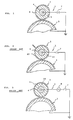
- the charging device 1 has a charging roller 2 held in contact with an image carrier implemented as a photoconductive drum 3 by way of example. While the charging roller 2 is in rotation, a high-tension DC voltage is applied from a DC power source 7 to the roller 2 to cause it to charge the drum 3.
- the charging roller 2 is made up of a metallic core 4, a conductive elastic layer 5 formed on the core 4 and having NBR or conductive particles dispersed therein, and a fluorine-based non-adhering film 10 provided with conductivity.
- the problem with this kind of charging roller 2 is that irregularity in electric characteristic is so great, the charge deposited on the drum 3 via the conductive elastic layer 15 is irregular. As a result, the background of an image is contaminated at a period coincident with the roller period.
- FIG. 3 shows a charging device using another conventional charging roller elaborated to eliminate the above problem.
- the same or similar constituent parts as or to the parts shown in FIG. 2 are designated by the same reference numerals, and a detailed description thereof will not be made in order to avoid redundancy.
- the charging roller 2 has an elastic layer 25 formed on the metallic core 4 and made of, for example, NBR, urethane or EPDM.
- a surface layer 11 is formed on the elastic layer 25 and has a conductive substance dispersed therein. The surface layer 11 is held in contact with the core 4.
- the DC power source 7 applies an AC-biased DC voltage to the core 4.
- the AC voltage biasing the DC voltage is provided with a peak-to-peak voltage twice as high as a charge start voltage to occur at the time when the DC voltage is applied.
- an AC power source 8 is necessary in addition to the DC power source 7 and results in an extra cost, in that a great amount of AC current which does not contribute to the charge potential of the drum 3 is wastefully consumed, and in that the AC current generates harmful ozone, as discussed earlier.
- a charging roller 2 has a metallic core 4, an elastic layer 5 formed on the core 4, and a surface layer 6 formed on the elastic layer 5.
- a DC power source 7 applies a high-tension negative DC voltage of 1.3 kV to 1.6 kV to cause it to charge a photoconductive drum 3.
- the elastic layer 5 is made of epichlorohydrin rubber having a medium electric resistance and in which conductive particles are not dispersed.
- the epichlorohydrin rubber may be implemented by a binary copolymer of epichlorohydrin/ethylene oxide or a ternary copolymer of epichlorohydrin/ethylene oxide/arylglycydil ether.
- the surface layer 6 is constituted by a mixture of epichlorohydrin rubber applied to the elastic layer 5 and non-adhering fluorine-based resin. This is to enhance the non-adhering property of the surface of the charge roller 2 against the deposition of toner particles.
- the fluorine-based resin is an amorphous polymer soluble to a solvent and produced by the copolymerization reaction of fluoroolefin and hydrocarbon-based vinyl ether.
- Kojima et al Japanese of the Institute of Organic Synthetic Chemical Engineers of Japan
- the fluorine-based resin has a relatively low fluorine content, i.e., 25 wt% to 32 wt%.
- the resin of this kind is an alternating copolymer in which fluoroolefin and hydrocarbon vinyl ether alternate with each other, the fluoroolefin portions which are thermochemically stable and regularly arranged protect the unstable hydrocarbon-based vinyl ether portions electronically and sterically. Hence, such a resin is chemically stable and durable.
- the resin, or amorphous polymer is soluble to a solvent and, therefore, has to be crosslinked after application, thereby providing the resulting film with resistivity to solvents.
- hydroxyl group-containing vinyl ether which is highly reactive is copolymerized with fluoroolefin so as to produce a resin structure which promotes easy crosslinking by isocyanate.
- the above structure allows the elastic layer 5 t o function with stability and uniformity as an electric resistance body and has a small electrostatic capacity. Therefore, even when AC is superposed on DC, the uniform charging ability is not improved to a noticeable degree. As a result, it is not necessary to superpose AC on DC, i.e., high-tension DC voltage should only be applied.
- the shaft was vulcanized at 170°C for 10 minutes and again vulcanized at 200°C for 2 hours.
- the surface of the resulting roller was machined to have a roller diameter of 12 mm.
- the roller was measured to have a medium electric resistance and, physically, a volume resistivity of 2 x 10 8 ⁇ cm, rubber hardness of 33° (JIS A), and surface roughness of 3 ⁇ m ⁇ Rz.
- the mixture was kneaded to prepare a compound having a uniform composition.
- 2.5 parts by weight of the compound was dissolved in a mixture solution of 48.8 parts by weight o f toluen and 48.8 parts by weight of 4-methyl-2-pentanone, thereby producing an epichlorohydrin rubber solution containing 2.5 % of solids (paint A-1).
- 22 parts by weight of solvent-soluble fluorine resin Liiflon LF-601C major agent available from Asahi Glass Co., Ltd. (Japan)
- isocyanate-based hardener Liiflon LF-601C hardener also available from Asahi Glass Co., Ltd.
- the charging roller 2 fabricated by the above procedure was substituted for a primary corona charger included in a positive-to-positive development type copier (FT3300 available from Ricoh Co. Ltd. (Japan)). In this condition, the roller 2 was held in contact with and rotated by the drum 3 while a DC voltage of 1.4 kV was applied to the core 4 thereof as a primary charge voltage.
- Table 1 which is shown below, indicates a light potential measured with the charging roller 2 together with the result of evaluation of an image in a row labeled Ex. (Example) 1. Even after the copier was operated to produce 5,000 copies, the potential and image were free from defects.
- each sample was left in a 20°C, 60 % RH atmosphere for 16 hours, use was made of an electrometer 610C, and an electrode for measurement was implemented by a tape of copper foil (No. 1245 available from 3M). Further, to measure the volume resistivity of the surface layer alone, the material constituting it was painted on a thin aluminum plate (0.2 mm thick) to a thickness of about 50 ⁇ m. Then, the aluminum plate was left in a 20°C, 60RH atmosphere for 16 hours; for the measurement, use was made of a resistance measuring cell (16008A available from YHP) and above-mentioned electrometer 610C.
- a resistance measuring cell 16008A available from YHP
- Example 2 is identical with Example 1 described above except that the surface layer 6 was 90 ⁇ m thick.
- Example 3 to produce the elastic layer 5, there were mixed 100 parts by weight of epichlorohydrin rubber of binary copolymer of epichlorohydrin/ethylene oxide (Epichromer C available from Daiso Co. Ltd. (Japan)), 30 parts by weight of more volatile calcium carbonate, 10 parts by weight of Sub (Neo factice GT available from Tenma Sub Chemicals Ltd. (Japan)), 5 parts by weight of zinc flower (Sazex I, Sakai Chemicals, Ltd. (Japan)), 0.5 part by weight of stearic acid (Stearic Acid SA-200, Asahi Denka Co, Ldt.
- Example 3 to form the surface layer 6, there were mixed and kneaded 100 parts by weight of epichlorohydrin rubber of binary copolymer (Epichlomer C available from Daiso Co. Ltd, (Japan)), 0.5 part by weight of stearic acid, 5 parts by weight of zinc flower, 1 part of vulcanization accelerator (Nocceler TT available from Ouchi Shinko Chemicals Inc. (Japan)), 1.5 parts by weight of Nocceler DM also available from Ouchi Shinko Chemicals, and 0.25 part by weight of Sulfax H available from Tsurumi Chemicals, thereby preparing a compound having a uniform composition.
- Epichlorohydrin rubber of binary copolymer (Epichlomer C available from Daiso Co. Ltd, (Japan)
- vulcanization accelerator Neler TT available from Ouchi Shinko Chemicals Inc. (Japan)
- Nocceler DM also available from Ouchi Shinko Chemicals
- Sulfax H available
- the mixture paint was coated on the elastic layer 5 by dipping, and then dried at 160°C for 30 minutes to form a 6 ⁇ m thick layer.
- the surface layer 6 had a volume resistivity of 1 x 10 10 ⁇ cm.
- the properties of the roller 2 are shown in Example 4 of Table 1.
- Example 5 corresponding to an embodiment of the present invention only the paint B was coated on the elastic layer 5 of Example 1 by dipping and then dried at 100°C for 30 minutes to form an 8 ⁇ m thick surface layer 6.
- the layer 6 had a volume resistivity of 2 x 10 14 ⁇ cm.
- the properties of the resulting roller 2 are indicated in Example 5 of Table 1.
- Example 6 corresponding to another embodiment of the present invention only the paint B was coated on the elastic layer 5 of Example 3 by dipping and then dried at 100°C for 30 minutes to form a 5 ⁇ m thick surface layer.
- the properties of the resulting roller 2 are shown in Example 6 of Table 1.
- Comparative Example (Comp. Ex.) 1 is representative of a case wherein a roller 2 had the elastic layer 5 of Example 1 and did not have the surface layer 6. It will be seen that when 5,000 copies are produced, irregular image density and toner filming occur.
- Comparative Example 2 is identical with Example 1 except that the surface layer 6 was 230 ⁇ m thick.
- the roller 2 had a hardness of 48° (JIS A).
- Comparative Example 3 only the paint B was coated on the elastic layer 5 of Example 4 by dipping and then dried at 100°C for 30 minutes to form a 30 ⁇ m thick surface layer 6. It will be seen that irregular image density and toner filming occur.
- Comparative Example 4 is identical with Example 6 except that the surface layer 6 was 11 ⁇ m thick.
- charge potential and, therefore, image density is slightly lowered, as Table 1 indicates.
- Comparative Example 5 is identical with Example 6 except that the surface layer 6 was 15 ⁇ m thick. In this case, charge potential and, therefore, image density is further lowered, as Table 1 also indicates.
- the present invention provides a charging roller having various unprecedented advantages, as enumerated below.
Landscapes
- Physics & Mathematics (AREA)
- Engineering & Computer Science (AREA)
- Plasma & Fusion (AREA)
- General Physics & Mathematics (AREA)
- Electrostatic Charge, Transfer And Separation In Electrography (AREA)
- Registering, Tensioning, Guiding Webs, And Rollers Therefor (AREA)
- Delivering By Means Of Belts And Rollers (AREA)
- Sheets, Magazines, And Separation Thereof (AREA)
- Rolls And Other Rotary Bodies (AREA)
Claims (2)
- Kontaktaufladewalze (2) zum Aufladen eines fotoleitfähigen Elements (3), enthalten in einer Bildgebungsvorrichtung, umfassend:eine elastische Schicht (5), hergestellt aus einer Substanz mit einem Volumenwiderstand von etwa 7 x 10⁷ bis 2 x 10⁸ Ωcm ; undeine Oberflächenschicht (6), ausgebildet auf der elastischen Schicht (5), dadurch gekennzeichnet, dass sie:nur aus einem Fluor enthaltenden Harz hergestellt ist, welches in einem Lösungsmittel löslich ist und welches nicht an Toner haftet, worin das Harz nach dem Auftrag quer vernetzt werden muss,worin das Harz, das ein Fluor enthaltendes, quer vemetztes Copolymer umfasst, durch Quervernetzen eines Fluor enthaltenden Copolymeren, das hergestellt ist aus Fluorolefin und einem Hydroxylgruppen enthaltenden Vinylether, mit Isocyanat hergestellt wird, undworin die Oberflächenschicht 5 µm bis 10µm dick ist.
- Kontaktaufladewalze wie in Anspruch 1 beansprucht, worin die Substanz der elastischen Schicht hauptsächlich besteht aus einem Epichlorhydrin-Gummi, implementiert durch ein tenäres Copolymer aus Epichlorohydrin/Ethylenoxid/Arylglycidyl oder ein binäres Copolymer aus Epichlorohydrin/Ethylenoxid oder eine Kombination derselben.
Applications Claiming Priority (7)
| Application Number | Priority Date | Filing Date | Title |
|---|---|---|---|
| JP367593 | 1993-01-13 | ||
| JP367593 | 1993-01-13 | ||
| JP3675/93 | 1993-01-13 | ||
| JP27059093 | 1993-10-28 | ||
| JP27059093A JPH06266206A (ja) | 1993-01-13 | 1993-10-28 | 帯電ローラ |
| JP270590/93 | 1993-10-28 | ||
| EP19940100436 EP0606907B1 (de) | 1993-01-13 | 1994-01-13 | Aufladerolle für ein Bilderzeugungsgerät |
Related Parent Applications (2)
| Application Number | Title | Priority Date | Filing Date |
|---|---|---|---|
| EP94100436.8 Division | 1994-01-13 | ||
| EP19940100436 Division EP0606907B1 (de) | 1993-01-13 | 1994-01-13 | Aufladerolle für ein Bilderzeugungsgerät |
Publications (3)
| Publication Number | Publication Date |
|---|---|
| EP0810486A2 EP0810486A2 (de) | 1997-12-03 |
| EP0810486A3 EP0810486A3 (de) | 1998-04-15 |
| EP0810486B1 true EP0810486B1 (de) | 2003-12-17 |
Family
ID=26337309
Family Applications (2)
| Application Number | Title | Priority Date | Filing Date |
|---|---|---|---|
| EP97107365A Expired - Lifetime EP0810486B1 (de) | 1993-01-13 | 1994-01-13 | Aufladewalze für ein Bilderzeugungsgerät |
| EP19940100436 Expired - Lifetime EP0606907B1 (de) | 1993-01-13 | 1994-01-13 | Aufladerolle für ein Bilderzeugungsgerät |
Family Applications After (1)
| Application Number | Title | Priority Date | Filing Date |
|---|---|---|---|
| EP19940100436 Expired - Lifetime EP0606907B1 (de) | 1993-01-13 | 1994-01-13 | Aufladerolle für ein Bilderzeugungsgerät |
Country Status (4)
| Country | Link |
|---|---|
| EP (2) | EP0810486B1 (de) |
| JP (1) | JPH06266206A (de) |
| DE (2) | DE69433430T2 (de) |
| ES (2) | ES2208783T3 (de) |
Families Citing this family (18)
| Publication number | Priority date | Publication date | Assignee | Title |
|---|---|---|---|---|
| US5610795A (en) * | 1994-08-01 | 1997-03-11 | Xerox Corporation | Self biasing charging member |
| EP0708382B1 (de) | 1994-10-18 | 2002-01-30 | Canon Kabushiki Kaisha | Verfahren zur Wiederherstellung eines Aufladungselements |
| JP3346970B2 (ja) * | 1994-11-22 | 2002-11-18 | 日本ゼオン株式会社 | ゴムロール、ゴム組成物、及び画像形成装置 |
| US5625858A (en) * | 1995-01-18 | 1997-04-29 | Canon Kabushiki Kaisha | Contact charging member, process for producing same and electrophotographic apparatus using same |
| JP3028057B2 (ja) * | 1996-02-21 | 2000-04-04 | 富士ゼロックス株式会社 | 帯電部材 |
| US5849399A (en) * | 1996-04-19 | 1998-12-15 | Xerox Corporation | Bias transfer members with fluorinated carbon filled fluoroelastomer outer layer |
| US6141516A (en) * | 1996-06-28 | 2000-10-31 | Xerox Corporation | Fluorinated carbon filled fluoroelastomer outer layer |
| JP3598718B2 (ja) * | 1997-03-25 | 2004-12-08 | 東海ゴム工業株式会社 | 半導電性ロール |
| US6558781B1 (en) | 1999-07-12 | 2003-05-06 | Canon Kabushiki Kaisha | Conductive roller, process cartridge and image forming apparatus |
| US6620476B2 (en) | 1999-08-13 | 2003-09-16 | Xerox Corporation | Nonbleeding fluorinated carbon and zinc oxide filled layer for bias charging member |
| US6203855B1 (en) | 1999-08-13 | 2001-03-20 | Xerox Corporation | Process for preparing nonbleeding fluorinated carbon and zinc oxide filler layer for bias charging member |
| EP1156388A1 (de) | 2000-05-16 | 2001-11-21 | Hokushin Corporation | Aufladungselement |
| US8483591B2 (en) | 2009-08-27 | 2013-07-09 | Xerox Corporation | Bias charging overcoat |
| JP5471176B2 (ja) * | 2009-08-28 | 2014-04-16 | 富士ゼロックス株式会社 | 導電性ローラ用組成物、導電性ローラ、帯電装置、画像形成装置およびプロセスカートリッジならびに導電性ローラの製造方法 |
| US8649704B2 (en) | 2009-11-20 | 2014-02-11 | Xerox Corporation | Bias charging overcoat |
| US8768219B2 (en) | 2009-11-20 | 2014-07-01 | Xerox Corporation | Bias charging overcoat |
| US9442451B2 (en) | 2014-11-28 | 2016-09-13 | Canon Kabushiki Kaisha | Electroconductive member for electrophotography, process cartridge, and electrophotographic image-forming apparatus |
| US10416588B2 (en) | 2016-10-31 | 2019-09-17 | Canon Kabushiki Kaisha | Charging member, process cartridge, electrophotographic image forming apparatus, and method for manufacturing charging member |
Family Cites Families (7)
| Publication number | Priority date | Publication date | Assignee | Title |
|---|---|---|---|---|
| US4727453A (en) * | 1986-12-22 | 1988-02-23 | Xerox Corporation | Alternating current inductive charging of a photoreceptor |
| JP2575209B2 (ja) * | 1989-07-05 | 1997-01-22 | キヤノン株式会社 | 電子写真用帯電部材および電子写真装置 |
| JPH0789249B2 (ja) * | 1989-09-14 | 1995-09-27 | キヤノン株式会社 | 画像形成装置 |
| JP2765660B2 (ja) * | 1990-07-20 | 1998-06-18 | キヤノン株式会社 | 帯電用部材 |
| JP3056273B2 (ja) * | 1991-03-28 | 2000-06-26 | キヤノン株式会社 | 帯電用部材 |
| JP3053246B2 (ja) * | 1991-04-10 | 2000-06-19 | 株式会社リコー | 半導電性ローラ |
| US5270768A (en) * | 1991-04-24 | 1993-12-14 | Canon Kabushiki Kaisha | Charging member containing reduced titanium oxide and device using same |
-
1993
- 1993-10-28 JP JP27059093A patent/JPH06266206A/ja active Pending
-
1994
- 1994-01-13 ES ES97107365T patent/ES2208783T3/es not_active Expired - Lifetime
- 1994-01-13 EP EP97107365A patent/EP0810486B1/de not_active Expired - Lifetime
- 1994-01-13 ES ES94100436T patent/ES2131593T3/es not_active Expired - Lifetime
- 1994-01-13 DE DE1994633430 patent/DE69433430T2/de not_active Expired - Lifetime
- 1994-01-13 EP EP19940100436 patent/EP0606907B1/de not_active Expired - Lifetime
- 1994-01-13 DE DE1994617931 patent/DE69417931T2/de not_active Expired - Lifetime
Also Published As
| Publication number | Publication date |
|---|---|
| EP0810486A2 (de) | 1997-12-03 |
| DE69417931T2 (de) | 1999-09-16 |
| EP0606907A1 (de) | 1994-07-20 |
| DE69433430T2 (de) | 2004-10-07 |
| ES2131593T3 (es) | 1999-08-01 |
| EP0606907B1 (de) | 1999-04-21 |
| DE69417931D1 (de) | 1999-05-27 |
| EP0810486A3 (de) | 1998-04-15 |
| ES2208783T3 (es) | 2004-06-16 |
| DE69433430D1 (de) | 2004-01-29 |
| JPH06266206A (ja) | 1994-09-22 |
Similar Documents
| Publication | Publication Date | Title |
|---|---|---|
| EP0810486B1 (de) | Aufladewalze für ein Bilderzeugungsgerät | |
| US5786091A (en) | Charge roller for an image forming apparatus | |
| US5761581A (en) | Image forming apparatus charging member formed of sequential overlying layers of elastic material | |
| US5312662A (en) | Conductive roll | |
| EP1031888B1 (de) | Aufladungselement, Verfahrenskassette und Bildherstellungsapparat | |
| JP3832057B2 (ja) | 現像ローラの製造方法 | |
| US5604031A (en) | Electrically conductive roll whose base layer is formed of ion-conductive elastic material | |
| JP2649163B2 (ja) | 導電性ロール | |
| US5792533A (en) | Electrostatic charging roller | |
| US20040247340A1 (en) | Electro-conductive roll and image-forming apparatus using the same | |
| JP2003221474A (ja) | 導電性部材 | |
| US6001454A (en) | Charging member and electrophotographic apparatus using the same | |
| JP3053246B2 (ja) | 半導電性ローラ | |
| JPH07164571A (ja) | 帯電ローラ | |
| US6175709B1 (en) | Toner support and image forming apparatus | |
| JPH05107874A (ja) | 半導電性ローラ | |
| JP3055463B2 (ja) | 導電性帯電部材 | |
| JP4371833B2 (ja) | 帯電部材、画像形成装置、帯電方法およびプロセスカートリッジ | |
| JPH06324553A (ja) | 帯電用部材及びこれを用いた帯電装置 | |
| JP3333069B2 (ja) | 帯電部材 | |
| JPH10148997A (ja) | 帯電ローラ | |
| JPH06324554A (ja) | 帯電用部材及びこれを用いた帯電装置 | |
| JPH05127494A (ja) | 半導電性ローラ | |
| JPH02311867A (ja) | 導電性ロール | |
| JP3401984B2 (ja) | 帯電用ロール |
Legal Events
| Date | Code | Title | Description |
|---|---|---|---|
| PUAI | Public reference made under article 153(3) epc to a published international application that has entered the european phase |
Free format text: ORIGINAL CODE: 0009012 |
|
| 17P | Request for examination filed |
Effective date: 19970505 |
|
| AC | Divisional application: reference to earlier application |
Ref document number: 606907 Country of ref document: EP |
|
| AK | Designated contracting states |
Kind code of ref document: A2 Designated state(s): DE ES FR GB IT |
|
| PUAL | Search report despatched |
Free format text: ORIGINAL CODE: 0009013 |
|
| AK | Designated contracting states |
Kind code of ref document: A3 Designated state(s): DE ES FR GB IT |
|
| 17Q | First examination report despatched |
Effective date: 19990329 |
|
| GRAH | Despatch of communication of intention to grant a patent |
Free format text: ORIGINAL CODE: EPIDOS IGRA |
|
| GRAA | (expected) grant |
Free format text: ORIGINAL CODE: 0009210 |
|
| GRAS | Grant fee paid |
Free format text: ORIGINAL CODE: EPIDOSNIGR3 |
|
| AC | Divisional application: reference to earlier application |
Ref document number: 0606907 Country of ref document: EP Kind code of ref document: P |
|
| AK | Designated contracting states |
Kind code of ref document: B1 Designated state(s): DE ES FR GB IT |
|
| REG | Reference to a national code |
Ref country code: GB Ref legal event code: FG4D |
|
| REF | Corresponds to: |
Ref document number: 69433430 Country of ref document: DE Date of ref document: 20040129 Kind code of ref document: P |
|
| REG | Reference to a national code |
Ref country code: ES Ref legal event code: FG2A Ref document number: 2208783 Country of ref document: ES Kind code of ref document: T3 |
|
| ET | Fr: translation filed | ||
| PLBE | No opposition filed within time limit |
Free format text: ORIGINAL CODE: 0009261 |
|
| STAA | Information on the status of an ep patent application or granted ep patent |
Free format text: STATUS: NO OPPOSITION FILED WITHIN TIME LIMIT |
|
| 26N | No opposition filed |
Effective date: 20040920 |
|
| PGFP | Annual fee paid to national office [announced via postgrant information from national office to epo] |
Ref country code: ES Payment date: 20090203 Year of fee payment: 16 |
|
| PGFP | Annual fee paid to national office [announced via postgrant information from national office to epo] |
Ref country code: IT Payment date: 20090127 Year of fee payment: 16 |
|
| REG | Reference to a national code |
Ref country code: ES Ref legal event code: FD2A Effective date: 20110228 |
|
| PG25 | Lapsed in a contracting state [announced via postgrant information from national office to epo] |
Ref country code: IT Free format text: LAPSE BECAUSE OF NON-PAYMENT OF DUE FEES Effective date: 20100113 |
|
| PG25 | Lapsed in a contracting state [announced via postgrant information from national office to epo] |
Ref country code: ES Free format text: LAPSE BECAUSE OF NON-PAYMENT OF DUE FEES Effective date: 20110224 |
|
| PG25 | Lapsed in a contracting state [announced via postgrant information from national office to epo] |
Ref country code: ES Free format text: LAPSE BECAUSE OF NON-PAYMENT OF DUE FEES Effective date: 20100114 |
|
| PGFP | Annual fee paid to national office [announced via postgrant information from national office to epo] |
Ref country code: DE Payment date: 20120123 Year of fee payment: 19 |
|
| PGFP | Annual fee paid to national office [announced via postgrant information from national office to epo] |
Ref country code: GB Payment date: 20120120 Year of fee payment: 19 |
|
| PGFP | Annual fee paid to national office [announced via postgrant information from national office to epo] |
Ref country code: FR Payment date: 20130213 Year of fee payment: 20 |
|
| GBPC | Gb: european patent ceased through non-payment of renewal fee |
Effective date: 20130113 |
|
| PG25 | Lapsed in a contracting state [announced via postgrant information from national office to epo] |
Ref country code: DE Free format text: LAPSE BECAUSE OF NON-PAYMENT OF DUE FEES Effective date: 20130801 |
|
| REG | Reference to a national code |
Ref country code: DE Ref legal event code: R119 Ref document number: 69433430 Country of ref document: DE Effective date: 20130801 |
|
| PG25 | Lapsed in a contracting state [announced via postgrant information from national office to epo] |
Ref country code: GB Free format text: LAPSE BECAUSE OF NON-PAYMENT OF DUE FEES Effective date: 20130113 |